Note: Descriptions are shown in the official language in which they were submitted.
CA 02567920 2006-11-22
WO 2005/118128 PCT/US2005/018271
Embolization
TECHNICAL FIELD
This invention relates to embolization, as well as related particles and
methods.
BACKGROUND
Therapeutic vascular occlusions (embolizations) are used to prevent or treat
pathological
conditions in situ. Compositions including embolic particles are used for
occluding vessels in a
variety of medical applications. Delivery of embolic particles through a
catheter is dependent on
size uniformity, density and compressibility of the embolic particles.
SUMMARY
In one aspect, the invention features a method of making particles. The method
includes
combining a plurality of streams (e.g., two streams, three streams) of fluid
to form drops, and
forming particles from the drops. The arithmetic mean diameter of the
particles is from about ten
microns to about 3,000 microns.
In another aspect, the invention features a method of making particles. The
method
includes combining a stream that includes a polymer and a different stream
that includes a
gelling precursor to form drops. The method also includes forming particles
from the drops.
In a further aspect, the invention features a method of making particles. The
method
includes forming a plurality of streams (e.g., two streams, three streams) of
fluid from a plurality
of orifices (e.g., two orifices, three orifices), combining the plurality of
streams of fluid to form
drops, and forming particles from the drops. A first orifice has a diameter of
from about 50
microns to about 1000 microns (e.g., from about 50 microns to about 300
microns). A second
orifice has an inner diameter of from about 50 microns to about 1000 inicrons
(e.g., from about
300 microns to about 600 microns) and an outer diaineter of from about 50
inicrons to about
1000 microns (e.g., from about 300 microns to about 600 inicrons). The outer
diameter of the
second orifice is different from the diameter of the first orifice.
Embodiments can include one or more of the following features.
The plurality of streams of fluid can include a first stream that includes a
first material
and a second stream that includes a second material.
1
CA 02567920 2006-11-22
WO 2005/118128 PCT/US2005/018271
The first material (e.g., a polymer) can form an interior region of the drops
and the
second material (e.g., a gelling precursor) can form a surface region of the
drops.
The first material can include a polymer, such as, for example, a polyvinyl
alcohol, a
polyacrylic acid, a polymetllacrylic acid, a poly vinyl sulfonate, a
carboxyinethyl cellulose, a
hydroxyethyl cellulose, a substituted cellulose, a polyacrylamide, a
polyethylene glycol, a
polyamide, a polyurea, a polyurethane, a polyester, a polyether, a
polystyrene, a polysacclzaride,
a polylactic acid, a polyethylene, a polymethylmethacrylate, a
polycaprolactone, a polyglycolic
acid, a poly(lactic-co-glycolic) acid, or a combination of two or more of
these polymers.
The second material can include a gelling precursor, such as a polysaccharide
(e.g.,
alginate).
The first material and the second material can be immiscible.
The first material and/or the second material can include a therapeutic agent.
The viscosity of the first material can be greater than the viscosity of the
second material.
The viscosity of the second material can be greater than the viscosity of the
first material.
The first material and/or second material can be ferromagnetic, MRI-visible
(visible by
magnetic resonance imaging), and/or radiopaque.
The first stream and the second stream can be concentric.
The method can further include contacting the first stream with the second
stream (e.g.,
by forming a mixture of the first and second materials).
The method can further include forming the first stream by flowing the first
material
through a first orifice that is defined by a nozzle.
The first material ca.n flow through the first orifice at a rate of from about
two milliliters
per miuute to about ten milliliters per minute.
The method can further include forming the second stream by flowing the second
material through a second orifice that is defined by the nozzle.
The second material can flow through the second orifice at a rate of from
about two
milliliters per minute to about 20 milliliters per minute.
The first orifice can be disposed within the second orifice. For example, the
first orifice
and the second orifice can be concentric.
The first orifice can be disposed at a vertical distance of about one
millimeter from the
second orifice.
2
CA 02567920 2006-11-22
WO 2005/118128 PCT/US2005/018271
The first orifice can have a diameter of from about 50 microns to about 1000
microns
(e.g., from about 50 microns to about 300 microns).
The second orifice can have an inner diameter of from about 50 microns to
about 1000
microns (e.g., from about 100 microns to about 600 microns, from about 300
microns to about
600 microns), and/or an outer diameter of from about 50 microns to about 1,000
microns (e.g.,
from about 100 microns to about 600 microns, from about 300 microns to about
600 inicrons).
The difference between the outer diameter of the second orifice and the
diameter of the
first orifice can be at least about 50 microns (e.g., about 100 microns).
The method can further include adding a therapeutic agent to the particles.
The method can further include contacting the drops with a gelling agent to
form the
particles.
Forming the particles can include converting the gelling precursor from a
solution into a
gel. The method can further include removing at least some of the gelling
precursor from the
particles.
The method can further include reacting the particles with a cross-linldng
agent.
The method can fi.irther include removing at least some of the gelling
precursor from the
particles.
One or more of the particles can have a diameter of from about ten microns to
about
3,000 microns. The particles can have an arithmetic mean diameter of from
about ten inicrons to
about 3,000 microns.
The interior region of the particles can be substantially free of the polymer
and of the
gelling precursor.
The density of the polymer in the interior region of the particles can be
higher than the
density of the polymer at the surface region of the particles. The density of
the gelling precursor
at the surface region of the particles can be higher than the density of the
gelling precursor in the
interior region of the particles.
The particles can contain pores. The density of pores in the interior region
of the
particles can be different from (e.g., greater than) the density of pores at
the surface region of the
particles. The average pore size in the interior region of the particles can
be different from (e.g.,
greater than) the average pore size at the surface region of the particles.
The particles can be substantially non-porous.
3
CA 02567920 2006-11-22
WO 2005/118128 PCT/US2005/018271
Forming the drops can include exposing the plurality of streams to a periodic
disturbance.
The periodic disturbance can be provided by vibrating the plurality of
streams.
Forming the drops can include establishing an electrostatic potential between
the plurality
of streams and a vessel configured to receive the drops.
Embodiments can include one or more of the following advantages.
The methods can provide for a relatively effective and/or efficient way to
make particles
(e.g., embolic particles), particularly particles that include more than one
material. For exainple,
different orifices can be used to introduce different materials during the
process of preparing the
particles. Particles including multiple materials can be desirable, for
example, in einbolization
procedures. As an example, it can be desirable for an embolic particle to
include a therapeutic
agent (e.g., to treat a tumor). As another example, it can be desirable for an
embolic particle to
include a radiopaque material (e.g., to ei-iliance the ability to view the
particle in the body using
fluoroscopy). As a further example, it can be desirable for an embolic
particle to include a
ferromagnetic material to enhance the ability to manipulate the position of
the particle in the
body using a magnetic field.
The methods can provide for a relatively effective and/or efficient way to
inake particles
(e.g., embolic particles) of a desired size. As an example, the streams of
material that flow fiom
different orifices can be independently manipulated to provide a particle of a
desired size. As
another example, the viscosity of the streams can be manipulated (e.g.,
reduced) to form particles
of a desired size (e.g., smaller particles).
The methods can, for example, be used to form hollow particles. Wl.ien used,
for
example, in an embolization procedure, hollow particles can be loaded shortly
before the
procedure (e.g., immediately before the procedure), which can reduce the cost
and/or complexity
associated with storing embolic compositions that include, for example, a
carrier solution in
addition to the particles.
Features and advantages are in the description, drawings, and claims.
DESCRIPTION OF DRAWINGS
FIG lA is a schematic of the manufacture of an embolic composition.
FIG 1B is an enlarged schematic of region 1B in FIG 1A.
4
CA 02567920 2006-11-22
WO 2005/118128 PCT/US2005/018271
FIG 2A is a cross-sectional view of an embodiment of an apparatus for
producing
particles.
FIG 2B is an enlarged view of the apparatus of FIG 2A, taken along line 2B-2B.
FIG 2C is an illustration of the production of particles by the apparatus of
FIGS. 2A and
2B.
FIG 3 is a cross-sectional view of an embodiment of a particle.
FIG 4 is a cross-sectional view of an einbodiment of a particle.
FIG 5 is a cross-sectional view of an embodiment of a particle.
FIG 6 is a cross-sectional view of an embodiment of a particle.
FIG 7A is a schematic illustrating injection of an embolic composition
including embolic
particles into a vessel, and FIG 7B is an enlarged view of region 7B in FIG
7A.
FIG 8 is a cross-sectional view of an embodiment of a particle.
FIG 9 is a cross-sectional view of an embodiment of a particle.
FIG 10 is a cross-sectional view of an embodiment of a particle.
FIG 11 is a cross-sectional view of an embodiment of a particle.
FIG 12 is a cross-sectional view of an embodiment of an apparatu.s for
producing
particles.
DETAILED DESCRIPTION
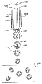
FIGS. 1A and 1B show a system 1000 for producing particles (e.g., particles
that can be
used in an embolization procedure). System 1000 includes a flow controller
1100, a drop
generator 1200, a gelling vessel 1400, a reactor vessel 1500, an optional gel
dissolution chamber
1600, and a filter 1700. Drop generator 1200 includes a concentric nozzle
1300. As shown in
FIGS. 2A and 2B, concentric nozzle 1300 includes an inner nozzle 1330 with an
inner volume
1335 and an orifice 1310 having a diameter "D." Concentric nozzle 1300 also
includes an outer
nozzle 1340 with an inner volume 1345 (shaded in FIG. 2A) and an orifice 1320
having an inner
diameter "ID" and an outer diameter "OD."
Drop generator 1200 can be, for example, the Inotech Encapsulator unit IE-
50R/NS
(Inotech AG, Dottilcon, Switzerland), or the model NISCO Encapsulation unit
VAR D (NISCO
Engineering, Zurich, Switzerland). In some embodiments, concentric nozzle 1300
can be
5
CA 02567920 2006-11-22
WO 2005/118128 PCT/US2005/018271
provided as an attachment to drop generator 1200. An exainple of a concentric
nozzle
attachment is the model IE-5250 attachment (available from Inotech AG).
Flow controller 1100 delivers two solutions (a polymer solution and a gelling
precursor
solution) to a viscosity controller 1800, which heats one or both of the
solutions to achieve their
respective desired viscosities prior to delivery to drop generator 1200. In
certain embodiments,
before being transferred to drop generator 1200, one or both of the solutions
can be introduced to
a high pressure pumping apparatus, such as a syringe pump (e.g., model
PHD4400, Haivard
Apparatus, Holliston, MA). Alternatively or additionally, drop generator 1200
can contain a
pressure control device that applies a pressure (e.g., from about 0.5 Bar to
about 1.6 Bar) to one
or both of the solutions (a pressure head) to control the rates at which the
solutions are
transferred to drop generator 1200. Generally, the pressure applied to a given
solution depends
on the viscosity of the solution and/or the desired flow rate of the solution.
As shown in FIG. 2C, after being delivered to drop generator 1200, a stream
1350 of the
polymer solution passes through volume 1335 and exits inner nozzle 1330 via
orifice 1310. A
stream 1360 of the gelling precursor solution passes through volume 1345 a.nd
exits outer nozzle
1340 via orifice 1320. In some embodiments, stream 1350 and/or stream 1360 can
have an
average diameter that is about two times the outer diameter of the nozzle
through which the
stream exits. The streains interact as they exit the orifices. At the same
time, nozzle 1300 is
subjected to a periodic disturbance which results in the formation of drops
1370 having an
interior region 1380 formed of the polymer and an exterior region 1390 formed
of the gelling
precursor. Drops 1370 fall into gelling vessel 1400, where the drops are
stabilized by gel
formation during which the gelling precursor is converted from a solution form
to a gel form.
The gel-stabilized drops are then transfeiTed from gelling vessel 1400 to
reactor vessel 1500,
where the polymer in the gel-stabilized drops is reacted, forming particles.
Thereafter, the
particles are filtered in filter 1700 to remove debris, and are sterilized and
packaged as an
embolic composition including embolic particles. In some embodiments, the
particles are
transferred, prior to filtration, to gel dissolution chamber 1600. In gel
dissolution chamber 1600,
the gelling precursor (which was converted to a gel) in the particles is
dissolved. After the
gelling precursor is dissolved, the particles can be filtered, sterilized, and
packaged, as described
above.
6
CA 02567920 2006-11-22
WO 2005/118128 PCT/US2005/018271
In general, one or more of the parameters of the drop generation process can
be selected
to form drops of a desired size. Drop size can be controlled, for example, by
controlling the
diaineter "D" of inner orifice 1310, the inner diaineter "ID" of orifice 1320,
the outer diameter
"OD" of orifice 1320, the flow rate of stream 1350, the flow rate of stream
1360, the viscosity of
the polymer solution, the viscosity of the gelling precursor solution, the
vibration amplitude of
concentric nozzle 1300, and/or the vibration frequency of concentric nozzle
1300. As an
example, holding otller parameters constant, increasing the diameter "D" of
inner orifice 1310,
increasing the inner diameter "ID" of orifice 1320, and/or increasing the
outer diameter "OD" of
orifice 1320 generally results in the formation of larger drops. As another
example, holding
other parameters constant, increasing the flow rate of stream 1350 and/or
increasing the flow rate
of stream 1360 generally results in larger drops. As an additional example,
holding other
parameters constant, reducing the vibration frequency of concentric nozzle
1300 generally results
in larger drops. As a further example, holding other parameters constant,
increasing the viscosity
of the polymer solution and/or increasing the viscosity of the gelling
precursor solution generally
results in larger drops.
In general, the diameter "D" of inner orifice 1310 can be from about 50
microns to about
1,000 inicrons (e.g., from about 50 microns to about 300 microns, from about
100 inicrons to
about 300 microns, from about 200 microns to about 300 microns, about 200
microns, about 300
microns). In some embodiments, diameter "D" can be about 300 microns or less
(e.g., about 200
microns or less, about 150 microns or less, about 100 microns or less) and/or
about 50 microns
or more (e.g., about 100 microns or more, about 150 microns or more, about 200
microns or
more, about 250 microns or more).
Orifice 1320 typically can have an outer diameter "OD" of from about 50
microns to
about 1,000 microns (e.g., from about 100 microns to about 600 microns, from
about 300
microns to about 600 microns, from about 300 microns to about 500 microns,
about 500 microns,
about 600 microns). In certain embodiments, orifice 1320 can have an outer
diameter "OD" of
about 100 microns or more (e.g., about 200 microns or more, about 300 microns
or more, about
400 microns or more, about 500 inicrons or more) and/or about 600 microns or
less (e.g., about
500 microns or less, about 400 microns or less, about 300 microns or less,
about 200 microns or
less).
7
CA 02567920 2006-11-22
WO 2005/118128 PCT/US2005/018271
Generally, orifice 1320 can have an inner diameter "ID" of from about 50
microns to
about 1,000 microns (e.g., from about 100 microns to about 600 microns, from
about 300
microns to about 600 microns, from about 300 microns to about 500 microns,
from about 400
microns to about 500 microns, about 400 microns, about 500 microns). In some
embodiments,
orifice 1320 can have an inner diameter "ID" of about 600 microns or less
(e.g., about 500
microns or less, about 400 microns or less, about 300 microns or less, about
200 microns or less)
and/or about 100 microns or more (e.g., about 200 microns or more, about 300
microns or more,
about 400 microns or more, about 500 microns or more).
The difference between the outer diameter "OD" of orifice 1320 and the
diaineter "D" of
inner orifice 1310 can be at least about 50 microns (e.g., at least about 100
microns, at least
about 200 microns, at least about 300 microns), and/or at most about 300
microns (e.g., at most
about 200 microns, at most about 100 microns). In some embodiments, the
difference between
the outer diameter "OD" of orifice 1320 and the diameter "D" of inner orifice
1310 can be about
100 microns.
In general, stream 1350 of polymer solution can flow through volume 1335 of
inner
nozzle 1330 at a rate of from about two milliliters per minute to about ten
milliliters per ininute.
In some embodiments, streain 1350 can flow through volume 1335 at a rate of
more than about
two milliliters per minute (e.g., more than about five milliliters per minute,
more than about
seven milliliters per ininute, more than about ten milliliters per minute)
and/or less than about ten
milliliters per minute (e.g., less than about seven milliliters per minute,
less thaii about five
milliliters per minute, less than about two milliliters per minute).
Generally, streain 1360 of gelling precursor solution can flow through volume
1345 at a
rate of from about two milliliters per ininute to about 20 milliliters per
minute (e.g., from about
four milliliters per minute to about 20 milliliters per minute, from about
five inilliliters per
minute to about 20 milliliters per minute). In some embodiments, stream 1360
can flow through
volume 1345 at a rate of more than about five milliliters per minute (e.g.,
more than about seven
milliliters per minute, more than about ten milliliters per minute, more than
about 15 milliliters
per minute) and/or less thazi about 20 milliliters per minute (e.g., less than
about 15 milliliters per
minute, less than about ten milliliters per minute, less than about seven
milliliters per minute).
8
CA 02567920 2006-11-22
WO 2005/118128 PCT/US2005/018271
In some embodiments, the flow rates of streams 1350 and 1360 are about the
same. For
example, streams 1350 and 1360 can both flow through concentric nozzle 1300 at
a rate of about
five milliliters per minute.
In certain embodiments, the flow rate of stream 1350 is different from the
flow rate of
stream 1360. For example, stream 1350 can flow through volume 1335 at a rate
of about five
milliliters per minute, and stream 1360 can flow through volume 1345 at a rate
of about ten
milliliters per minute. In some embodiments, a variation in the flow rates of
streams 1350 and
1360 through nozzle 1300 can enhance mixing between the streams at their
interface.
In some embodiments, stream 1360 can begin to flow through concentric nozzle
1300
before stream 1350 begins to flow through concentric nozzle 1300. In certain
embodiinents,
streain 1350 can begin to flow through concentric nozzle 1300 before stream
1360 begins to flow
through concentric nozzle 1300. In such embodiments, mixing between the
streams at the
interface can be relatively low.
In some embodiments, the vibration frequency of concentric nozzle 1300 can be
about
0.1 KHz or more (e.g., about 0.8 KHz or more, about 1.5 KHz or more, about
1.75 K-Hz or more,
about 1.85 KHz or more, about 2.5 KHz or more, from about 0.1 KHz to about 0.8
KHz).
In certain embodiments, the vibration amplitude of concentric nozzle 1300 is
larger than
the width of the drops 1370. In some einbodiments, drop generator 1200 has a
variable vibration
amplitude setting, such that an operator can adjust the amplitude of the
concentric nozzle
vibration. In such einbodiments, the vibration amplitude can be set, for
example, at between
about 80 percent and about 100 percent of the maximum setting.
In general, the viscosity of the polymer solution can be from about ten
centipoise to about
50 centipoise (e.g., about 25 centipoise). Alternatively or additionally, the
viscosity of the
gelling precursor solution can be from about ten centipoise to about 100
centipoise (e.g., about
50 centipoise). In some embodiments, a solution with a viscosity of about 50
centipoise can
produce drops with a diaineter of from about 100 microns to about 1200
microns. Typically, the
viscosity of a concentric stream of two different materials can be lower than
the viscosity of a
mixed stream of the two different materials. Generally, a lower viscosity
solution can flow
through a smaller orifice than a higher viscosity solution, and tlius can
produce smaller drops
than the higher viscosity solution.
9
CA 02567920 2006-11-22
WO 2005/118128 PCT/US2005/018271
As described above, viscosity controller 1800 can be used in the drop
formation process
to control the viscosity of the polymer solution and the gelling precursor
solution. Viscosity
controller 1800 is a heat exchanger that circulates water at a predetermined
temperature about the
flow tubing between the pump and drop generator 1200. The polymer solution and
the gelling
precursor solution flow into viscosity controller 1800, where the solutions
are heated so that their
viscosities are lowered to a desired level. Alternatively or additionally,
vessels containing the
solutions can be disposed in a heated fluid bath (e.g., a heated water bath)
to heat the solutions.
In some einbodiments (e.g., when the system does not contain viscosity
controller 1800), flow
controller 1100 and/or drop generator 1200 can be placed in a temperature-
controlled chamber
(e.g. an oven, a heat tape wrap) to the heat polymer solution and the gelling
precursor solution.
In general, for a given solution, the lower the desired viscosity of the
solution, the higher the
temperature to which the solution is heated. For example, in some embodiments,
a solution with
a desired viscosity of about 100 centipoise can be heated to a temperature of
about 65 C, while a
solution with a desired viscosity of about 50 centipoise can be heated to a
temperature of about
75 C. In certain embodiments, viscosity controller 1800 can heat the solutions
to allow for flow
through an orifice of a particular size. Generally, for a given solution, the
smaller the size of the
nozzle orifice, the higher the temperature to which the solution is heated.
For example, in some
embodiments, a solution that flows through an orifice witli a diameter of
about 200 microns can
be heated to a temperature of about 65 C, while the same solution, when
flowing through an
orifice with a diameter of about 100 microns, can be heated to a temperature
of about 75 C.
The viscosity of the polymer solution and/or the gelling precursor solution
can
alternatively or additionally be adjusted by changing the concentration of the
polymer and/or
gelling precursor in the solution. In general, as the concentration of polymer
and/or gelling
precursor in the solution increases, the viscosity of the solution increases.
If, for example, the
desired viscosity of a polyvinyl alcohol solution is about 25 centipoise, then
the solution can be
prepared to have a concentration of about eight percent polyvinyl alcohol. If,
for example, the
desired viscosity of an alginate solution is about 50 centipoise, then the
solution can be prepared
to have a concentration of about two percent alginate.
The pressure applied to the gelling precursor solution and/or the polymer
solution in the
drop formation process can be selected, for exainple, based on the desired
size of the drops
and/or the viscosities of the solutions. In general, for a given solution, as
the size of the nozzle
CA 02567920 2006-11-22
WO 2005/118128 PCT/US2005/018271
orifice decreases (e.g., to produce smaller particles), the pressure applied
to the solution
increases. For exainple, a pressure of about 0.5 Bar can be applied to a
solution with a viscosity
of about 50 centipoise that flows through an orifice with a diameter of about
300 microns. A
pressure of about 0.8 Bar can be applied to the same solution with the saine
viscosity when the
solution flows through an orifice with a diameter of about 200 microns.
Generally, for a given
solution flowing through an orifice of a given diameter, as the viscosity of
the solution decreases,
the pressure that is applied to the solution decreases. For example, a
pressure of about 0.8 Bar
can be applied to a solution with a viscosity of about 50 centipoise when the
solution flows
through an orifice witll a diameter of about 200 microns. A pressure of about
0.5 Bar can be
applied to the same solution when the solution flows through the same orifice,
but has a different
viscosity (e.g., about 25 centipoise).
In general, the distance between gelling vessel 1400 and inner orifice 1310
and/or orifice
1320 is selected so that the drops are separated before reaching vessel 1400.
In some
embodiments, the distance from inner orifice 1310 and/or orifice 1320 to the
mixture contained
in gelling vessel 1400 is from about five inches to about eight inches (e.g.,
from about five
inches to about six inches).
In general, the polymer solution and gelling precursor solution can be formed
according
to any of a number of different methods. In some embodiments, the polymer
solution and/or
gelling precursor solution can be formed by dissolving one or more polymers
and/or gelling
precursors in water prior to use in drop generator 1200. The polymer can, for
example, be
dissolved in water by heating (e.g., above about 70 C or more, about 121 C).
The gelling
precursor can, for example, be dissolved in water at room temperature. In
certain embodiments,
the polymer solution and/or the gelling precursor solution can be foimed by
mixing water with
one or more polymers and/or gelling precursors and heating the mixture in an
autoclave. Heat
can alternatively or additionally be applied to a mixture of water and one or
more polymers
and/or gelling precursors by, for exainple, microwave application. In some
einbodiments, a
homogenizer (e.g., in combination with microwave application) can be used to
mix the water
with the polymer(s) and/or gelling precursor(s).
Generally, the polymer or polymers used in the polymer solution, and the
gelling
precursor or precursors used in the gelling precursor solution, are
biocompatible.
11
CA 02567920 2006-11-22
WO 2005/118128 PCT/US2005/018271
Examples of polymers include polyvinyl alcohols, polyacrylic acids,
polymethacrylic
acids, poly vinyl sulfonates, carboxyniethyl celluloses, hydroxyethyl
celluloses, substituted
celluloses, polyacrylamides, polyethylene glycols, polyainides, polyureas,
polyurethanes,
polyesters, polyethers, polystyrenes, polysaccharides, polylactic acids,
polyethylenes,
polymethylmethacrylates, polycaprolactones, polyglycolic acids, poly(lactic-co-
glycolic) acids
(e.g., poly(d-lactic-co-glycolic) acids) and copolymers or mixtures thereof. A
preferred polymer
is polyvinyl alcohol (PVA). The polyvinyl alcohol, in particular, is typically
hydrolyzed in the
range of from about 80 percent to about 99 percent. The weight average
molecular weight of the
base polymer can be, for example, in the range of from about 9000 to about
186,000 (e.g., from
about 85,000 to about 146,000, from about 89,000 to about 98,000).
Examples of gelling precursors include alginates, alginate salts, xanthan
gums, natural
gum, agar, agarose, chitosan, carrageenan, fucoidan, furcellaran, laminaran,
hypnea, eucheuma,
gum arabic, gum ghatti, gum karaya, gum tragacanth, hyalauronic acid, locust
beam gum,
arabinogalactan, pectin, amylopectin, other water soluble polysaccharides and
other ionically
cross-linkable polyiners. A particular gelling precursor is sodium alginate. A
preferred sodium
alginate is high guluronic acid, stem-derived alginate (e.g., about 50 percent
or more, about 60
percent or more guluronic acid) with a low viscosity (e.g., from about 20
centipoise to about 80
centipoise at 20 C), which produces a high tensile, robust gel.
The mixture contained in gelling vessel 1400 includes a gelling agent which
interacts
with the gelling precursor to stabilize drops by forming a stable gel.
Suitable gelling agents
include, for example, a charged polyiner (e.g., polyacrylic acid), or a
divalent cation such as
alkali metal salt, alkaline earth metal salt or a transition metal salt that
can ionically cross-link
with the gelling precursor. An inorganic salt, for exainple, a calcium,
barium, zinc or
magnesium salt can be used as a gelling agent. In embodiments, particularly
those using an
alginate gelling precursor, a suitable gelling agent is calcium chloride. The
calcium cations have
an affinity for carboxylic groups in the gelling precursor. The cations
complex with carboxylic
groups in the gelling precursor, resulting in encapsulation of the polymer by
the gelling
precursor.
Without wishing to be bound by theory, it is believed that in some embodiments
(e.g.,
when forming particles having a diameter of about 500 microns or less), it can
be desirable to
reduce the surface tension of the mixture contained in gelling vessel 1400.
This can be achieved,
12
CA 02567920 2006-11-22
WO 2005/118128 PCT/US2005/018271
for example, by heating the mixture in gelling vessel 1400 (e.g., to a
temperature greater than
room temperature, such as a temperature of about 30 C or more (e.g., a
temperature of about
80 C or more)), by bubbling a gas (e.g., air, nitrogen, argon, krypton,
helium, neon) through the
mixture contained in gelling vessel 1400, by stirring (e.g., via a magnetic
stilTer) the mixture
contained in gelling vessel 1400, by including a surfactant in the mixture
containing the gelling
agent, and/or by forming a mist containing the gelling agent above the
inixture contained in
gelling vessel 1400 (e.g., to reduce the formation of tails and/or enhance the
sphericity of the
particles).
As noted above, following drop stabilization, the gelling solution can be
decanted froin
the solid drops, or the solid drops can be removed from the gelling solution
by sieving. The solid
drops are then transfeiTed to reactor vessel 1500, where the polymer in the
solid drops is reacted
(e.g., cross-linked) to produce particles.
Reactor vessel 1500 contains an agent that chemically reacts with the polymer
to cause
cross-linlcing between polymer chains and/or within a polymer chain. For
example, in
embodiments in which the polymer is polyvinyl alcohol, vessel 1500 can include
one or more
aldehydes, such as formaldehyde, glyoxal, benzaldehyde, aterephthalaldehyde,
succinaldehyde
and glutaraldehyde for the acetalization of polyvinyl alcohol. Vessel 1500
also can include an
acid, for example, strong acids such as sulfuric acid, hydrochloric acid,
nitric acid and weak
acids such as acetic acid, formic acid and phosphoric acid. In embodiments,
the reaction is
primarily a 1,3-acetalization:
H+
--(-CH-CHZ-CH-CHZ-)-- + CH2=O __> --(-CH-CH2-CH-CHZ-)-- + H20
I I 65 C I 1
OH OH O O
CH2
This intra-chain acetalization reaction can be carried out with relatively low
probability
of inter-chain cross-linking, as described in John G. Pritchard, "Poly(Vinyl
Alcohol) Basic
Properties and Uses (Polymer Monograph, vol. 4) see p. 93-97), Gordon and
Breach, Science
Publishers Ltd., London, 1970, which is incorporated herein by reference.
Because the reaction
13
CA 02567920 2006-11-22
WO 2005/118128 PCT/US2005/018271
proceeds in a random fashion, some OH groups along a polymer chain might not
react with
adjacent groups and may remain unconverted.
Adjusting for the amounts of aldehyde and acid used, reaction time and
reaction
temperature can control the degree of acetalization. In einbodiments, the
reaction time is from
about five minutes to about one hour (e.g., from about 10 minutes to about 40
minutes, about 20
minutes). The reaction temperature can be, for example, from about 25 C to
about 150 C (e.g.,
from about 75 C to about 130 C, about 65 C). Reactor vessel 1500 can be placed
in a water bath
fitted with an orbital motion mixer. The particles are washed several times
witli deionized water
to remove residual acidic solution.
FIG. 3 shows a particle 10 that can be formed by the process noted above
(without
dissolving the gelling precursor). Particle 10 includes an interior region 12
formed of the
polymer and an exterior region 16 formed of the gelling precursor (which is in
a gelled state as
explained above).
In general, particle 10 can have a diameter of from about ten microns to about
3,000
microns (e.g., from about 40 microns to about 2,000 microns; from about 100
microns to about
700 microns; from about 500 microns to about 700 microns; from about 100
microns to about
500 microns; from about 100 microns to about 300 microns; from about 300
microns to about
500 microns; from about 500 microns to about 1,200 microns; from about 500
microns to about
700 microns; from about 700 microns to about 900 microns; from about 900
microns to about
1,200 microns). In some embodiments, particle 10 can have a diameter of about
3,000 microns
or less (e.g., about 2,500 microns or less; about 2,000 microns or less; about
1,500 microns or
less; about 1,200 microns or less; about 1,000 microns or less; about 900
microns or less; about
700 microns or less; about 500 microns or less; about 400 microns or less;
about 300 microns or
less; about 100 microns or less) and/or about ten microns or more (e.g., about
100 microns or
more; about 300 microns or more; about 400 microns or more; about 500 microns
or more; about
700 microns or more; about 900 microns or more; about 1,000 microns or more;
about 1,200
microns or more; about 1,500 microns or more; about 2,000 inicrons or more;
about 2,500
microns or more).
In certain embodiments, particle 10 can have a sphericity of about 0.8 or more
(e.g.,
about 0.85 or more, about 0.9 or more, about 0.95 or more, about 0.97 or
more). The sphericity
of a particle can be determined using a Beclanan Coulter RapidVUE Image
Analyzer version
14
CA 02567920 2006-11-22
WO 2005/118128 PCT/US2005/018271
2.06 (Beckman Coulter, Miami, FL). Briefly, the RapidVUE talces an image of
continuous-tone
(gray-scale) form and converts it to a digital form through the process of
sampling and
quantization. The system software identifies and measures particles in an
image in the form of a
fiber, rod or sphere. The sphericity of a particle, which is coinputed as
Da/Dp (where Da =
~(4A/n); Dp = Phr ; A = pixel area; P = pixel perimeter), is a value from zero
to one, with one
representing a perfect circle.
As noted above, in some embodiments, the gelling precursor (in a gelled state)
is
removed from particles 10 (e.g., by an ion exchange reaction), forming
particles 100, shown in
FIG. 4. Particles 100 include the polymer but are substantially free of the
gelling precursor. In
some embodiments in which the gelling precursor is formed of sodium alginate,
the sodium
alginate is removed by ion exchange with a solution of sodium hexa-
metaphosphate (EM
Science). The solution can include, for example, ethylenediaminetetracetic
acid (EDTA), citric
acid, other acids, and phosphates. The concentration of the sodium hexa-
metaphosphate can be,
for example, from about one weight percent to about 20 weight percent (e.g.,
from about one
weight percent to about ten weight percent, about five weight percent) in
deionized water.
Residual gelling precursor (e.g., sodium alginate) can be measured by assay
(e.g., for the
detection of uronic acids in, for example, alginates containing mannuronic and
guluronic acid
residues). A suitable assay includes rinsing the particles with sodium
tetraborate in sulfuric acid
solution to extract alginate, combining the extract with metahydroxydiphenyl
colormetric
reagent, and determining concentration by UV/VIS spectroscopy. Testing can be
carried out by
alginate suppliers such as FMC Biopolymer, Oslo, Norway. Residual alginate may
be present in
the range of, for example, from about 20 weight percent to about 35 weight
percent prior to
rinsing, and in the range of from about 0.01 weight percent to about 0.5
weight percent (e.g.,
from about 0.1 weight percent to about 0.3 weight percent, about 0.18 weight
percent) in the
particles after rinsing for 30 minutes in water at about 23 C.
In some embodiments, and as shown in FIGS. 5 and 6, the gelling precursor can
be
removed from a particle to form a smaller particle with a rough surface. FIG.
5 shows a particle
200 with an interior region 210 that includes a polymer and an exterior region
230 that includes a
gelling precursor. A boundary 250 between the gelling precursor and the
polymer is not well-
defined. Such a boundary can be formed, for example, when there is some mixing
between the
gelling precursor solution and the polymer solution at the interface between
the two solutions
CA 02567920 2006-11-22
WO 2005/118128 PCT/US2005/018271
during the formation of particle 200. When the gelling precursor is removed
from particle 200, a
particle 300 having a rough surface 310, shown in FIG. 6, can result. Particle
300 is formed
substantially of the polymer and is substantially free of the gelling
precursor.
As noted above, after either cross-linking or reinoval of the gelling
precursor, the
particles formed using concentric nozzle 1300 are filtered through filter 1700
to remove residual
debris. Particles of from about 100 microns to about 300 microns can filtered
through a sieve of
about 710 microns and then a sieve of about 300 microns. The particles can
then be collected on
a sieve of about 20 microns. Particles of from about 300 to about 500 inicrons
can filtered
through a sieve of about 710 inicrons and then a sieve of about 500 microns.
The particles can
then be collected on a sieve of about 100 microns. Particles of from about 500
to about 700
microns can be filtered through a sieve of about 1000 microns, then filtered
through a sieve of
about 710 microns, and then a sieve of about 300 microns. The particles can
then be collected in
a catch pan. Particles of from about 700 to about 900 microns can be filtered
through a sieve of
1000 microns and then a sieve of 500 microns. The particles can then be
collected in a catch
pan. Particles of from about 900 to about 1200 microns can filtered tlirough a
sieve of 1180
microns and then a sieve of 710 microns. The particles can then be collected
in a catch pan.
Other size sieves can be used if desired.
The particles are then packaged. Typically, from about one milliliter to about
five
milliliters of particlesare paclcaged in from about five milliliters to about
ten milliliters of saline.
The filtered particles then are typically sterilized by a low teinperature
technique, such as e-beam
irradiation. In embodiments, electron beam iiTadiation can be used to
pharmaceutically sterilize
the particles (e.g., to reduce bioburden). In e-beam sterilization, an
electron beam is accelerated
using magnetic and electric fields, and focused into a beam of energy. The
resultant energy
beain can be scanned by means of an electromagnet to produce a "curtain" of
accelerated
electrons. The accelerated electron beam penetrates the collection of
particles, destroying
bacteria and mold to sterilize and reduce the bioburden in the particles.
Electron beam
sterilization can be carried out by sterilization vendors such as Titan Scan,
Lima, Ohio.
In some embodiments, multiple particles are combined with a carrier fluid
(e.g., a
phatmaceutically acceptable carrier, such as a saline solution, a contrast
agent, or both) to form
an embolic composition. In general, the density of the particles (e.g., as
measured in grams of
material per unit volume) is such that they can be readily suspended in the
carrier fluid and
16
CA 02567920 2006-11-22
WO 2005/118128 PCT/US2005/018271
remain suspended during delivery. In some einbodiments, the density of a
particle is from about
1.1 grams per cubic centimeter to about 1.4 grams per cubic centimeter. As an
example, for
suspension in a saline-contrast solution, the density can be from about 1.2
grains per cubic
centimeter to about 1.3 grains per cubic centimeter.
Embolic coinpositions can be used in, for example, neural, pulmonary, and/or
AAA
(abdominal aortic aneurysm) applications. The compositions can be used in the
treatment of, for
example, fibroids, tumors, internal bleeding, arteriovenous inalformations
(AVMs), and/or
hypervascular tumors. The coinpositions can be used as, for example, fillers
for aneurysm sacs,
AAA sac (Type II endoleaks), endolealc sealants, arterial sealants, and/or
puncture sealants,
and/or can be used to provide occlusion of other lumens such as fallopian
tubes. Fibroids can
include uterine fibroids which grow within the uterine wall (intramural type),
on the outside of
the uterus (subserosal type), inside the uterine cavity (submucosal type),
between the layers of
broad ligament supporting the uterus (interligamentous type), attached to
another organ (parasitic
type), or on a mushroom-like stalk (pedunculated type). Internal bleeding
includes
gastrointestinal, urinary, renal and varicose bleeding. AVMs are for example,
abnormal
collections of blood vessels, e.g. in the brain, which shunt blood from a high
pressure artery to a
low pressure vein, resulting in hypoxia and malnutrition of those regions from
which the blood is
diverted. Iii some embodiments, a composition containing the particles can be
used to
prophylactically treat a condition.
The magnitude of a dose of an embolic coinposition can vary based on the
nature,
location and severity of the condition to be treated, as well as the route of
administration. A
physician treating the condition, disease or disorder can determine an
effective amount of
embolic composition. An effective ainount of embolic composition refers to the
ainount
sufficient to result in amelioration of symptoms or a prolongation of survival
of the subject. The
embolic compositions can be administered as pharmaceutically acceptable
compositions to a
subject in any therapeutically acceptable dosage, including those administered
to a subject
intravenously, subcutaneously, percutaneously, intratrachealy,
intramuscularly, intramucosaly,
intracutaneously, intra-articularly, orally or parenterally.
An embolic composition can include a mixture of particles (e.g., particles
that include
different types of therapeutic agents), or can include particles that are all
of the same type. In
some embodiments, an embolic composition can be prepared with a calibrated
concentration of
17
CA 02567920 2006-11-22
WO 2005/118128 PCT/US2005/018271
particles for ease of delivery by a physician. A pllysician can select an
embolic composition of a
particular concentration based on, for example, the type of embolization
procedure to be
performed. In certain embodiments, a physician can use an embolic composition
witli a
relatively high concentration of particles during one part of an embolization
procedure, and an
embolic composition with a relatively low concentration of particles during
another part of the
embolization procedure.
Suspensions of particles in saline solution can be prepared to remain stable
(e.g., to
remain suspended in solution and not settle and/or float) over a desired
period of time. A
suspension of particles can be stable, for example, for from about one minute
to about 20
minutes (e.g. fioin about one minute to about ten minutes, from about two
minutes to about
seven minutes, from about three minutes to about six minutes).
In some embodiments, particles can be suspended in a physiological solution by
matching the density of the solution to the density of the particles. In
certain embodiinents, the
particles and/or the physiological solution can have a density of fiom about
one gram per cubic
centimeter to about 1.5 grams per cubic centimeter (e.g., from about 1.2 grams
per cubic
centimeter to about 1.4 grams per cubic centimeter, from about 1.2 grams per
cubic centimeter to
about 1.3 grams per cubic centimeter).
FIGS. 7A and 7B show an embolization procedure in which an embolic composition
including embolic particles 400 and a carrier fluid is injected into a vessel
through an instrument
such as a catheter 410. Catheter 410 is connected to a syringe barrel 420 with
a plunger 430.
The embolic composition is loaded into syringe barrel 420, and catheter 410 is
inserted, for
example, into a femoral artery 440 of a patient. Plunger 430 of syringe barrel
420 is then
compressed to deliver the embolic composition through catheter 410 into a
lumen 450 of a
uterine artery 460 that leads to a fibroid 470 located in the uterus of the
patient. The embolic
composition can, for example, occlude uterine artery 460.
As shown in FIG. 7B, uterine artery 460 is subdivided into smaller uterine
vessels 480
(e.g., having a diameter of about two millimeters or less) which feed fibroid
470. Particles 400
in the embolic composition partially or totally fill the lumen of uterine
artery 460, either partially
or completely occluding the lumen of the uterine artery 460 that feeds uterine
fibroid 470.
In some embodiments, among the particles delivered to a subject in an einbolic
composition, the majority (e.g., about 50 percent or more, about 60 percent or
more, about 70
18
CA 02567920 2006-11-22
WO 2005/118128 PCT/US2005/018271
percent or more, about 80 percent or more, about 90 percent or more) of the
particles can have a
diameter of about 3,000 microns or less (e.g., about 2,500 microns or less;
about 2,000 microns
or less; about 1,500 microns or less; about 1,200 microns or less; about 900
microns or less;
about 700 microns or less; about 500 microns or less; about 400 microns or
less; about 300
microns or less; about 100 microns or less) and/or about ten microns or more
(e.g., about 100
microns or more; about 300 microns or more; about 400 microns or more; about
500 inicrons or
more; about 700 microns or more; about 900 microns or more; about 1,200
microns or more;
about 1,500 microns or more; about 2,000 microns or more; about 2,500 microns
or more).
In certain embodiments, the particles delivered to a subject in an embolic
composition
can have an arithmetic mean diameter of from about ten microns to about 3,000
microns. In
some embodiments, the particles can have an arithmetic mean diameter of about
3,000 microns
or less (e.g., about 2,500 microns or less; about 2,000 inicrons or less;
about 1,500 microns or
less; about 1,200 microns or less; about 900 microns or less; about 700
microns or less; about
500 microns or less; about 400 microns or less; about 300 microns or less;
about 100 inicrons or
less) and/or about ten microns or more (e.g., about 100 microns or more; about
300 microns or
more; about 400 microns or more; about 500 microns or more; about 700 microns
or more; about
900 microns or more; about 1,200 microns or more; about 1,500 microns or more;
about 2,000
microns or more; about 2,500 microns or more). Exeinplary ranges for the
arithmetic mean
diaineter of particles delivered to a subject include from about 100 microns
to about 300
microns; from about 300 microns to about 500 microns; from about 500 microns
to about 700
microns; and from about 900 microns to about 1,200 microns. In general, the
particles delivered
to a subject in an embolic composition can have an arithmetic mean diameter in
approximately
the middle of the range of the diameters of the individual particles, and a
variance of about 20
percent or less (e.g. about 15 percent or less, about ten percent or less).
In some embodiments, the arithmetic mean diameter of the particles delivered
to a subject
in an embolic composition can vary depending upon the particular condition to
be treated. As an
example, in embodiments in which the particles in an embolic composition are
used to treat a
liver tumor, the particles delivered to the subject can have an arithmetic
mean diameter of about
500 microns or less (e.g., from about 100 microns to about 300 microns; from
about 300 microns
to about 500 microns). As another example, in embodiments in which the
particles in an embolic
composition are used to treat a uterine fibroid, the particles delivered to
the subject in an embolic
19
CA 02567920 2006-11-22
WO 2005/118128 PCT/US2005/018271
composition can have an arithmetic mean diameter of about 1,200 microns or
less (e.g., from
about 500 microns to about 700 microns; from about 700 inicrons to about 900
microns; from
about 900 microns to about 1,200 microns).
The arithmetic mean diameter of a group of particles can be determined using a
Beckman
Coulter RapidVUE Image Analyzer version 2.06 (Beclanan Coulter, Miami, FL),
described
above. The arithmetic mean diameter of a group of particles (e.g., in a
composition) can be
determined by dividing the sum of the diameters of all of the particles in the
group by the
number of particles in the group.
In certain embodiments, the sphericity of a particle after compression in a
catheter (e.g.,
after compression to about 50 percent or more of the cross-sectional area of
the particle) can be
about 0.8 or more (e.g., about 0.85 or more, about 0.9 or more, about 0.95 or
more, about 0.97 or
more). The particle can be, for example, manually coinpressed, essentially
flattened, while wet
to about 50 percent or less of its original diameter and then, upon exposure
to fluid, regain a
sphericity of about 0.8 or more (e.g., about 0.85 or more, about 0.9 or more,
about 0.95 or more,
about 0.97 or more).
While substantially spherical particles have been shown, in some embodiments a
concentric nozzle can be used to make one or more non-spherical particles. For
example, a
concentric nozzle can be used to make crescent-shaped particles, as shown in
FIGS. 8 and 9.
FIG. 8 shows a precursor particle 800, fonned by a concentric nozzle.
Precursor particle 800 has
a crescent-shaped interior region 810 that includes a polymer, and an exterior
region 830 that
includes a gelling precursor. Exterior region 830 can be removed (e.g., by
exposing precursor
particle 800 to a gel dissolution chamber) to produce crescent-shaped particle
900, shown in FIG.
9, which is formed substantially of polymer. While precursor particles with
interior crescent-
shaped regions have been shown, in some embodiments precursor particles with
exterior
crescent-shaped regions can be formed. In certain emboditnents, precursor
particles with
crescent-shaped regions can be formed by using a first material and a second
material that has a
much greater (e.g., by 50 centipoise) viscosity than the first material. In
some einbodiments,
precursor particles with crescent-shaped regions can be formed by using a
higher flow rate (e.g.,
about 15 milliliters per minute) for the stream that flows througli one nozzle
(e.g., the outer
nozzle) of a concentric nozzle and a lower flow rate (e.g., about seven
milliliters per minute) for
the stream that flows through another nozzle (e.g., the inner nozzle) of the
concentric nozzle.
CA 02567920 2006-11-22
WO 2005/118128 PCT/US2005/018271
Other Embodiments
While certain embodiments have been described, the invention is not so
limited.
As an example, while embodiments have been described in which a polymer
solution
flows through the inner nozzle and a gelling precursor solution flows through
the outer nozzle, in
some embodiments, a polyiner solution flows through the outer nozzle and a
gelling precursor
solution flows through the inner nozzle. If the gelling precursor is not
dissolved, the resulting
particles can have, for example, an interior region formed of gelling
precursor (in a gelled state)
and an exterior region formed of polymer. FIG. 10 shows such a particle 500
having an interior
region 510 formed of gelling precursor (in a gelled state) and an exterior
region 530 formed of
polymer. If the gelling precursor is dissolved, the resulting particles can
have, for example, a
hollow interior and an exterior region formed of polymer. FIG. 11 shows such a
particle 600
having a hollow interior region 610 and exterior region 530 (formed of
polymer). 111 certain
embodiments, particle 600 can be used to deliver one or more agents (e.g.,
therapeutic agents)
into the body (see discussion below). For example, the agent(s) can be
injected into hollow
interior region 610 of particle 600 prior to delivery.
As another example, while embodiments of a concentric nozzle having two
nozzles have
been described, other embodiments are possible. In general, a concentric
nozzle can have more
than two (e.g., three, four, five, six, seven, eight, nine, ten) nozzles.
Typically, each nozzle in a
concentric nozzle has a stream of a particular material that flows
therethrough. In some
embodiments, however, a stream of a particular material may flow through more
than one
nozzle.
As a further example, in some embodiments drops may be formed without
vibrating the
concentric nozzle. In certain embodiments, drops can be formed by establishing
an electrostatic
potential between concentric nozzle 1300 and gelling vessel 1400 so that the
streams exiting
concentric nozzle 1300 are pulled toward gelling vessel 1400, tllereby forming
drops. An
electrostatic potential can be established, for example, by charging
concentric nozzle 1300 and
charging gelling vessel 1400 with the opposite charge. For example, concentric
nozzle 1300 can
be negatively charged and gelling vessel 1400 can be positively charged. An
example of a
commercially available drop generator that forms drops by the use of an
electrostatic potential is
the NISCO Encapsulation unit VAR V1 (NISCO Engineering, Zurich, Switzerland).
In some
21
CA 02567920 2006-11-22
WO 2005/118128 PCT/US2005/018271
embodiments, drops can be formed by using a drop generator that employs botli
an electrostatic
potential and a periodic disturbance (e.g., vibration of the concentric
nozzle). In certain
embodiments, drops can be formed by mechanically breaking the streams exiting
concentric
nozzle 1300 into drops 1370 (e.g., by a jet cutter). Optionally, drops may be
formed by using a
combination of vibration techniques and/or mechanical break-up techniques
and/or electrostatic
tecluiiques.
As an additional example, in some embodiments, drop generator 1200 can charge
drops
1370 after formation and prior to contact with the gelling agent, such that
mutual repulsion
between drops 1370 prevents drop aggregation as the drops travel from drop
generator 1200 to
gelling vessel 1400. Charging may be achieved, for example, by an
electrostatic charging device
such as a charged ring positioned downstreain of concentric nozzle 1300.
As an additional example, while the formation of crescent-shaped particles has
been
described, in some einbodiments, a drop generation process can be perforined
in a way that
limits the likelihood of forming crescent-shaped particles and/or particles
with crescent-shaped
regions. For exainple, a polymer solution that flows through the volume
defined by an inner
nozzle of a concentric nozzle can include a relatively small concentration
(e.g., up to about one
percent) of a gelling agent (e.g., calcium ions). The presence of gelling
agent in the polyiner
solution can reduce the likelihood of formation of particles with crescent-
shaped regions (such as
precursor particle 800 in FIG. 8). While not being bound by theory, it is
believed that the gelling
agent in the polymer solution can cause the polymer to begin to gel prior to
the formation of a
drop containing the polymer. If, for example, a gelling precursor solution is
flowing through the
outer nozzle of the concentric nozzle, then when the drop that is fonned
contacts gelling agent,
both the interior region and the exterior region of the drop may gel. Thus,
the drop can be
gelling from both the inside out and the outside in. Such gelling may result
in particles in which
both the interior regions and the exterior regions are substantially
spherical.
As another example, in certain embodiments, one or more of the materials that
flow
through one or more of the orifices in a concentric nozzle can be a
therapeutic agent (e.g., drug),
such that particles formed by the concentric nozzle incorporate the
therapeutic agent(s).
Alternatively or additionally, one or more therapeutic agents can be added to
the particles after
fonning the particles. In some embodiments, a therapeutic agent can be added
to a particle by,
e.g., injection of the therapeutic agent into the particle and/or by soalcing
the particle in the,
22
CA 02567920 2006-11-22
WO 2005/118128 PCT/US2005/018271
therapeutic agent. Therapeutic agents include agents that are negatively
charged, positively
charged, amphoteric, or neutral. Therapeutic agents can be, for example,
materials that are
biologically active to treat physiological conditions; pharmaceutically active
compounds; gene
therapies; nucleic acids with and without carrier vectors; oligonucleotides;
gene/vector systems;
DNA chimeras; compacting agents (e.g., DNA compacting agents); viruses;
polymers;
llyaluronic acid; proteins (e.g., enzymes such as ribozymes); cells (of human
origin, from an
animal source, or genetically engineered); stem cells; immm.iologic species;
nonsteroidal anti-
inflaminatory medications; oral contraceptives; progestins; gonadotrophin-
releasing hormone
agonists; chemotherapeutic agents; and radioactive species (e.g.,
radioisotopes, radioactive
molecules). Non-limiting examples of therapeutic agents include anti-
thrombogenic agents;
antioxidants; angiogenic and anti-angiogenic agents and factors; anti-
proliferative agents (e.g.,
agents capable of blocking smooth muscle cell proliferation); anti-
inflammatory agents; calcium
entry blockers; antineoplastic/antiproliferative/anti-mitotic agents (e.g.,
paclitaxel, doxorubicin,
cisplatin); antimicrobials; anesthetic agents; anti-coagulants; vascular cell
growth promoters;
vascular cell growth inhibitors; cholesterol-lowering agents; vasodilating
agents; agents which
interfere with endogenous vasoactive mechanisms; and survival genes which
protect against cell
death. In some embodiments, release of a therapeutic agent from a particle can
be triggered by
one or more factors. For example, release of a therapeutic agent can be
triggered by pH, ions,
and/or temperature. Therapeutic agents are described, for example, in co-
pending U.S. Patent
Application Publication No. US 2004/00765 82 Al, published on Apri122, 2004,
which is
incorporated herein by reference.
As an additional example, in some embodiments, one or more of the materials
that flows
through one or more of the orifices in a concentric nozzle can be a diagnostic
agent (e.g., a
radiopaque material, a material that is visible by magnetic resonance imaging
(an MRI-visible
material), an ultrasound contrast agent). In some einbodiinents, one or more
of the materials
used in concentric nozzle can be a ferromagnetic material. Al.ternatively or
additionally, one or
more diagnostic agents and/or ferromagnetic materials can be added to the
particles after forming
the particles. In some embodiments, a diagnostic agent and/or ferromagnetic
material can be
added to a particle by, e.g., injection of the diagnostic agent and/or
ferromagnetic material into
the particle and/or by soaking the particle in the diagnostic agent and/or
ferromagnetic material.
Diagnostic agents and ferromagnetic materials are described in U.S. Patent
Application
23
CA 02567920 2006-11-22
WO 2005/118128 PCT/US2005/018271
Publication No. US 2004/0101564 Al, published on May 27, 2004, and entitled
"Embolization",
which is incorporated herein by reference.
As another example, in certain embodiments, one or more of the materials that
flow
through one or more of the orifices in a concentric nozzle can be a shape
memory material,
which is capable of being configured to remember (e.g., to change to) a
predetermined
configuration or shape. In some embodiments, particles that include a shape
memory material
can be selectively transitioned from a first state to a second state. For
example, a heating device
provided in the interior of a delivery catheter can be used to cause a
particle including a shape
memory material to tra.nsition from a first state to a second state. Shape
memory materials and
particles that include shape memory materials are described in, for example,
U.S. Patent
Application Publication No. US 2004/0091543 Al, published on May 13, 2004, and
U.S. Patent
Application No. 10/791,103, filed March 2, 2004, and entitled "Embolic
Compositions", both of
which are incorporated herein by reference.
As an additional example, in some embodiments, one or more of the materials
that flow
through one or more of the orifices in a concentric nozzle can be a surface
preferential material.
Surface preferential materials are described, for example, in U.S. Patent
Application No.
10/791,552, filed on March 2, 2004, and entitled "Embolization", which is
incorporated herein
by reference.
As a further example, in certain embodiments, a particle can be coated (e.g.,
with a
bioabsorbable material). For example, a particle can have an interior region
including a
radiopaque material, an exterior region including a polymer, and a hydrogel
coating over the
exterior region. The coating can contain, for exainple, one or more
therapeutic agents. In certain
embodiments, a particle can be coated to include a higli concentration of one
or more therapeutic
agents and/or one or more of the therapeutic agents can be loaded into the
interior of the particle.
The surface of the particle can release an initial dosage of therapeutic agent
after which the body
of the particle can provide a burst release of therapeutic agent. The
therapeutic agent on the
surface of the particle can be the same as or different fiom the therapeutic
agent in the body of
the particle. The therapeutic agent on the surface can be applied by exposing
the particle to a
high concentration solution of the therapeutic agent. The therapeutic agent
coated particle can
include another coating over the surface the therapeutic agent (e.g., a
degradable and/or
bioabsorbable polymer which erodes when the particle is administered). The
coating can assist
24
CA 02567920 2006-11-22
WO 2005/118128 PCT/US2005/018271
in controlling the rate at which therapeutic agent is released from the
particle. For exainple, the
coating can be in the form of a porous membrane. The coating can delay an
initial burst of
therapeutic agent release. The coating can be applied by dipping or spraying
the particle. The
erodible polymer can be a polysaccharide (such as an alginate). In some
embodiments, the
coating can be an inorganic, ionic salt. Other erodible coatings include water
soluble polyiners
(such as polyvinyl alcohol, e.g., that has not been cross-linked),
biodegradable poly DL-lactide-
poly ethylene glycol (PELA), hydrogels (e.g., polyacrylic acid, haluronic
acid, gelatin,
carboxymethyl cellulose), polyethylene glycols (PEG), chitosan, polyesters
(e.g.,
polycaprolactones), and poly(lactic-co-glycolic) acids (e.g., poly(d-lactic-co-
glycolic) acids).
The coating can include therapeutic agent or can be substantially free of
therapeutic agent. The
therapeutic agent in the coating can be the same as or different from an agent
on a surface layer
of the particle and/or within the particle. A polymer coating, e.g. an
erodible coating, can be
applied to the particle surface in embodiments in which a hig11 concentration
of therapeutic agent
has not been applied to the particle surface. Coatings are described, for
example, in U.S. Patent
Application Publication No. US 2004/0076582 Al, published on April 22, 2004,
which is
incorporated herein by reference.
As an additional example, in certain embodiments, one or more of the materials
that
flows througll one or more of the orifices in a concentric nozzle can be
bioerodible, such that the
materials can eventually brealc down in the body and either be dispersed
throughout the body or
excreted from the body. A bioerodible material can be, for example, a
polysaccharide (such as
an alginate); a polysaccharide derivative; an inorganic, ionic salt; a water
soluble polyiner (such
as a polyvinyl alcohol, e.g., that has not been cross-linked); biodegradable
poly DL-lactide-poly
ethylene glycol (PELA); a hydrogel (e.g., polyacrylic acid, haluronic acid,
gelatin,
carboxyinethyl cellulose); a polyethylene glycol (PEG); chitosan; a polyester
(e.g., a
polycaprolactone); a poly(lactic-co-glycolic) acid (e.g., a poly(d-lactic-co-
glycolic) acid); or a
coinbination thereof.
As a fiirther example, in some einbodiments, a particle produced by a
concentric nozzle
can include one of the following combinations of materials: an interior region
including a
ferromagnetic material (e.g., iron, an iron oxide (e.g., Fe304), magnetite, a
ferrofluid) and an
exterior region including a polymer (e.g., a polysaccharide); an interior
region including one type
of therapeutic agent and an exterior region including a different type of
therapeutic agent; or an
CA 02567920 2006-11-22
WO 2005/118128 PCT/US2005/018271
interior region that includes a ferromagnetic material and an exterior region
that includes a
combination of a polymer and a gelling precursor.
As another example, in some embodiments the materials used in a concentric
nozzle to
form particles can be selected based on their immiscibility, such that streams
of the materials can
remain substantially discrete as they flow through drop generator 1200. In
such embodiments,
the streams can produce particles having an exterior region of substantially
one material and an
interior region of substantially another material.
As an additional example, in some embodiments, one or more of the solutions
that flows
through one or more of the orifices in a concentric nozzle can be chilled
prior to entering the
concentric nozzle (e.g., to affect the viscosity and/or flow rate of the
solution).
As a further example, in certain einbodiments, the materials that flow through
a
concentric nozzle can be selected to mix with each other upon contact. For
example, one
material can be a ferromagnetic material, wliile the other material is
polyvinyl alcohol.
As another example, while concentric nozzles have been described that have two
orifices,
in some embodiments a concentric nozzle can include more than two orifices
(e.g., three orifices,
four orifices, five orifices).
As an additional example, in certain embodiments, the orifices in a concentric
nozzle can
be vertically spaced apart from each other. For example, FIG. 12 shows a
concentric nozzle 700
that includes an imier nozzle 710 concentrically disposed within an outer
nozzle 720. Inner
nozzle 710 has an inner orifice 712, and outer nozzle 720 has an outer orifice
722. Inner orifice
712 is separated from outer orifice 722 by a vertical distance "V", which can
be from about 0.5
millimeter to about two millimeters (e.g., about one millimeter). In some
embodiments, vertical
displacement of the orifices of a concentric nozzle can enhance mixing of the
solutions flowing
tlirough the nozzle prior to the point at which the solutions contact the
gelling agent. In such
embodiments, drops formed by the nozzle can include a mixture of the
solutions. In certain
embodiments, mixing of the solutions within the concentric nozzle can be
enhanced by starting
to flow one of the solutions through the outer nozzle of the concentric nozzle
prior to starting to
flow the other solution through the inner nozzle of the concentric nozzle.
As another example, in some embodiments, the particles can be mechanically
shaped
during or after the particle formation process to be nonspherical (e.g.,
ellipsoidal). In certain
embodiments, one or more particles can be shaped (e.g., molded, compressed,
punched, and/or
26
CA 02567920 2006-11-22
WO 2005/118128 PCT/US2005/018271
agglomerated with other particles) at different points in the particle
manufacturing process. In
some embodiments (e.g., where the polymer is a polyvinyl alcohol and the
gelling precursor is
sodium alginate), after contacting the particles with the gelling agent but
before cross-linking,
the particles can be physically deformed into a specific shape and/or size.
After shaping, the
polymer (e.g., polyvinyl alcohol) can be cross-linked, optionally followed by
substantial removal
of the gelling precursor (e.g., alginate). While substantially spherical
particles are preferred,
non-spherical particles can be manufactured and formed by controlling, for
example, drop
formation conditions. In some embodiments, nonspherical particles can be
formed by post-
processing the particles (e.g., by cutting or dicing into other shapes).
Particle shaping is
described, for example, in co-pending U.S. Patent Application Publication No.
US 2003/0203985
Al, published on October 30, 2003, which is incorporated herein by reference.
As a further example, in some embodiments, particles having different shapes,
sizes,
physical properties, and/or cheinical properties, can be used together in an
embolization
procedure. The different particles can be delivered into the body of a subject
in a predetermined
sequence or siinultaneously. In certain embodiments, mixtures of different
particles can be
delivered using a multi-lumen catheter andlor syringe. In some einbodiments,
particles having
different shapes and/or sizes can be capable of interacting synergistically
(e.g., by engaging or
interlocking) to form a well-packed occlusion, thereby enhancing embolization.
Particles with
different shapes, sizes, physical properties, and/or chemical properties, and
methods of
embolization using such particles are described, for exainple, in U.S. Patent
Application
Publication No. US 2004/0091543 Al, published on May 13, 2004, and in U.S.
Patent
Application No. 10/791,103, filed March 2, 2004, and entitled "Embolic
Compositions", botll of
which are incorporated herein by reference.
As an additional example, in some embodiments the particles can be used for
tissue
bulking. As an example, the particles can be placed (e.g., injected) into
tissue adjacent to a body
passageway. The particles can narrow the passageway, thereby providing bullc
and allowing the
tissue to constrict the passageway more easily. The particles can be placed in
the tissue
according to a number of different methods, for example, percutaneously,
laparoscopically,
and/or through a catheter. In certain embodiments, a cavity can be formed in
the tissue, and the
particles can be placed in the cavity. Particle tissue bullcing can be used to
treat, for example,
intrinsic sphincteric deficiency (ISD), vesicoureteral reflux,
gastroesophageal reflux disease
27
CA 02567920 2006-11-22
WO 2005/118128 PCT/US2005/018271
(GERD), and/or vocal cord paralysis (e.g., to restore glottic competence in
cases of paralytic
dysphonia). In some embodiments, particle tissue bulking can be used to treat
urinary
incontinence and/or fecal incontinence. The particles can be used as a graft
material or a filler to
fill and/or to smooth out soft tissue defects, such as for reconstructive or
cosmetic applications
(e.g., surgery). Examples of soft tissue defect applications include cleft
lips, scars (e.g.,
depressed scars from chicken pox or acne scars), indentations resulting from
liposuction,
wrinkles (e.g., glabella frown wrinkles), and soft tissue auginentation of
thin lips. Tissue bulking
is described, for example, in co-pending U.S. Patent Application Publication
No.
US 2003/0233150 Al, published on December 18, 2003, which is incorporated
herein by
reference.
As a further exainple, in some embodiments a particle can be porous and/or can
include
one or more cavities. hl certain embodiments, the particle can have a
substantially uniform pore
structure. In some embodiments, the particle can have a non-uniform pore
structure. For
example, the particle can have a substantially non-porous interior region
(e.g., formed of a
polyvinyl alcohol) and a porous exterior region (e.g., formed of a mixture of
a polyvinyl alcohol
and alginate). Porous particles are described in U.S. Published Patent
Application No.
US 2004/0096662 Al, published on May 20, 2004, which is incorporated herein by
reference.
As another example, in some embodiments a solution can be added to the
concentric
nozzle to enhance the porosity of particles produced by the concentric nozzle.
Examples of
porosity-enhancing solutions include starch, sodium chloride at a relatively
high concentration
(e.g., more than about 0.9 percent, from about one percent to about five
percent, from about one
percent to about two percent), and calcium chloride (e.g., at a concentration
of at least about 50
mM). For example, calcium chloride can be added to a sodium alginate gelling
precursor
solution to increase the porosity of the particles produced from the solution.
As an additional example, in certain embodiments, the particles that are
produced by a
concentric nozzle can be linked together to form particle chains. For example,
the particles can
be connected to each other by links that are formed of one or more of the same
material(s) as the
particles, or of one or more different material(s) from the particles.
Alternatively or additionally,
the concentric nozzle can be used to form particle chains. For example, the
vibration frequency
of the concentric nozzle can be selected to cause the concentric nozzle to
form particle chains.
Particle chains and methods of making particle chains are described, for
example, in U.S. Patent
28
CA 02567920 2006-11-22
WO 2005/118128 PCT/US2005/018271
Application No. 10/830,195, filed on Apri122, 2004, and entitled
"Embolization", which is
incorporated herein by reference.
Other einbodiments are in the claims.
29