Note: Descriptions are shown in the official language in which they were submitted.
CA 02568318 2006-11-16
GUARD RAIL BASE AND GUARD RAIL SUPPORT
FIELD OF INVENTION
[0001) This invention relates to safety barriers used in the construction of
high-rise
and other buildings, and more particularly, relates to a base for a guard rail
of the kind
which is constructed from lumber.
BACKGROUND OF THE INVENTION
[0002] The construction of modem high-rise buildings usually requires
temporary
barriers to be erected on the building perimeter for all floors as the work
progresses
until exterior walls are in place. The barriers must be secure to ensure the
safety of
the persons working at the construction site and preferably, the barriers
should be easy
to install and to remove for reuse. Conveniently, guard rails are constructed
from
lumber which is inexpensive and readily available in the form of posts having
standard dimensions of two inches by four inches (2x4). Transverse wood rails
are
nailed to the posts to complete the assembly of the guard rail. The support
surface on
which the guard rail is erected may be a concrete deck but may also be a wood
form
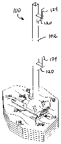
forming part of a shoring platform to provide a base for poured concrete.
[0003] In known devices, the lumber pieces comprising upright posts for the
guard
rail are secured to the support surface using a base fabricated from steel
which has a
socket dimensioned to receive the lumber and extending from one side of a
planar
base member. Both the socket and base member are apertured to receive threaded
wood fasteners for securing the base to the lumber and to the support surface
respectively. Where the support surface is concrete, a wood base is first
secured to the
concrete so that the base member can be screwed to the wood base. Preferably,
the
socket is formed at one end of the support base so that the base is more
stable and
cannot readily be pried away from the support surface.
[0004] An object of this invention is to provide a base which is easily
installed and
removed for reuse and a more convenient guard rail support.
-2-
CA 02568318 2006-11-16
SUMMARY OF THE INVENTION
[0005] In accordance with this invention, there is provided a base for a
vertical post
forming part of a guard rail system, the base having an open socket
dimensioned for
receiving the post and a base member. The socket has a transversely extending
notch
pin rotatably mounted between opposite sides of the socket and adapted to
engage the
post upon rotation thereof to cut a notch in the post. A locking lever fixed
to the
notch pin is provided to rotate the pin into and out of engagement with the
post.
[0006] The invention also provides a nail guide in the base member which has a
plurality of nail guiding apertures oriented to receive fasteners from
opposite
directions so that the fasteners may bite into an underlying support surface.
[0007] In accordance with another aspect of the invention, the base member is
provided with an integral post to replace the socket, the post having at least
one
bracket vertically spaced from the base and adapted to receive and locate a
transversely disposed removable barrier.
BRIEF DESCRIPTION OF THE DRAWINGS
[0008] In order that the invention can be more clearly understood, a preferred
embodiment is described below with reference to the accompanying drawings, in
which:
[0009] Fig. 1 is a perspective view of a guard rail system with a base in
accordance
with the invention assembled on a deck;
[0010] Figs. 2a to 2c are side elevation views of the base in accordance with
the
invention showing various positions of a locking lever and partly cut away to
show a
notch pin;
[0011 ] Fig. 3 is a top plan view of the base in accordance with the
invention;
[0012] Fig. 4a is a side elevation view of a post of lumber notched by the
invention
(exaggerated for illustration);
[0013] Fig. 4b is a perspective view of the post of Fig. 4a;
-3-
i n I- 1 CA 02568318 2006-11-16
[0014] Fig. 5 is a perspective view of the base being installed on a wood
deck;
[0015] Fig. 6 is a side elevation view, partly sectioned, showing the nail
entry position
into the base through a wood deck;
[0016] Fig. 7 is a similar view to Fig. 5 showing the base being installed on
a concrete
deck;
[0017] Fig. 8 is a perspective view of an alternative embodiment of the
invention
showing a post with support brackets formed integrally with the base;
[0018] Fig. 9 is a perspective view showing a pair of posts according to the
invention
in use to support a removable barrier in the form of rails, and
[0019] Fig. 10 is a similar view to Fig. 9 showing a pair of posts according
to the
invention in use to support a removable barrier in the form of a fence.
DESCRIPTION OF PREFERRED EMBODIMENTS WITH
REFERENCE TO DRAWINGS
[0020] A guard rail system coupled to a base 20 in accordance with the
invention is
shown in Fig. 1 assembled on a wood deck 22. The guard rail consists of a
safety
fence 24 mounted on the interior side of a building under construction and
braced by a
support post in the form of a piece of lumber 26 disposed on the exterior side
of the
building. Conveniently, the piece of lumber 26 is made of soft wood such as
pine and
has conventional dimensions of 2 inches by 4 inches (2x4). The base 20 has an
upwardly extending socket 28 which is of rectangular cross-section and is
dimensioned to receive the piece of lumber 26. It will be noted that the
socket 28 is
somewhat larger than the piece of lumber 26 and in this case is approximately
5
inches long.
[0021] As will be seen in the top plan view of Fig. 3, the socket 28 is formed
by two
pairs of opposite sides 30, 32 and 34, 36. Between opposite sides 30, 32 there
is a
transversely extending notch pin 38 which is rotatably mounted at one end of
the
socket. It will be noted that the notch pin 38 is asymmetric and has a flat
side 40
which is aligned with an axis of rotation for the pins 38 as indicated by
reference
numeral 42. A locking lever 44 is fixed to the notch pin 38 on the exterior of
the
socket 28 and is adapted to rotate the notch pin 38 into and out of engagement
with
-4-
CA 02568318 2006-11-16
the piece of lumber 26 as illustrated by the drawings of Figs. 2a, 2b and 2c.
It will be
appreciated that such rotation of the locking lever 44 as indicated by arrows
46, 48
will cause the notch pin to carve a notch 50 into the lumber as shown in Figs.
4a and
4b where the notch 50 is somewhat exaggerated for purposes of illustration.
Simultaneously with such engagement into the lumber piece 26 of the notch pin
38,
the piece of lumber 26 will be moved downwardly as indicated by arrows 52, 54
so as
to be seated into the socket 28. A stop pin 55 (Fig. 2c) disposed inside the
socket 28
beneath the notch pin operates to limit displacement of the post 26 inside the
socket.
Conveniently, a viewing aperture 56 is provided in one of the sides 32 for
visual
inspection of the socket 28 and to ensure that the piece of lumber 26 is
properly
seated. The viewing aperture 56 will also operate to drain any rain water from
the
socket 28 thereby minimizing the likelihood of the piece of lumber 26 becoming
rotten from excess moisture build up in the socket.
[0022] The socket 28 extends from one side of a base member and the base
member is
apertured to receive fasteners to secure the base to a support surface, as
will be
described. Conveniently, the socket 28 is formed from a tubular steel section
which is
welded at one end to a bottom plate extending forwardly and rearwardly from
opposite
sides 34, 36 to define a rearward wing 58 and a forward wing 60 and a closed
bottom
62 for the socket 28. Each section of the bottom plate is apertured with
apertures 64,
66, 68 respectively for receiving anchors 70 to secure the base 20 according
to the
invention to a concrete deck 72 as illustrated in Fig. 7. In order to increase
stability
and rigidity of the base 20, a transverse brace 74 extends between the top of
the socket
28 and a forward end of the forward wing 60. Conveniently, a security cable
(not
shown) may be threaded through the opening formed by the brace 74 and the
socket
28 to connect a shipment of guard rail bases made in accordance with the
invention
and to discourage pilfering.
[0023] It will be observed that the locking lever 44 has a free end which is
spaced
from the brace 74 by a bend in the lever of sufficient width to accommodate a
user's
hand between the lever and the brace and socket arrangement. The rearward wing
58
spaces a nail guide identified by reference numeral 76 which is used to secure
the base
to a wood deck 22 as illustrated by Figs. 5 and 6. The nail guide is in the
form of a
steel rod bent into a C-shaped configuration and having a plurality of nail
guiding
-5-
M I ~ I =
CA 02568318 2006-11-16
apertures 78 spaced from each other along the length of the rod and oriented
to receive
nails 80 from opposite directions so that the nails may bite into the
underlying wood
deck 22. The number of nails used will in part depend on the condition of the
wood
deck as fewer nails would be required for a new plywood underlay, for example.
The
nail guiding apertures 78 are sufficiently spaced from each other that the
underlying
wood deck is not shredded and will continue to hold the nails as illustrated
schematically in Fig. 6. In addition, the nail guiding apertures are oriented
to receive
the nails 80 at an angle of 30 to 60 degrees relative to the support surface,
an angle of
45 degrees having been found to be adequate to allow the nails to penetrate
into the
wood and also withstand accidental prying which would loosen the guard rail
base 20
from the deck. The nail guiding apertures 78 nearest to the rearward wing 58
of the
bottom plate are also angled at 20 as seen in the plan view of Fig. 3 in
order to
provide sufficient clearance between the nail guide 76 and the socket 28 for a
hammer.
[0024] In most applications, eight nails will be sufficient but additional
nail guiding
apertures 78 are provided should the need arise to use more nails. Still
further
security is provided by the nail guiding apertures 78 formed in lateral nail
guide
portions 82, 84 which extend parallel to the rearward wing 58. Conveniently,
the
lateral nail guide portions 82, 84 may be used as a carrying handle for
manually
carrying the base 20 at a job site.
[0025] In some applications, it may be desirable to use other fasteners such
as wood
screws instead of nails.
[0026] In use, pieces of lumber 26 are selected for use as bracing posts to
form part of
a guard rail system and are spaced around the perimeter of the building under
construction. At selected locations, the base 20 made in accordance with the
invention will be secured to the underlying deck using nails in the case of a
wood deck
or anchors in the case of a concrete deck. Once secured to the deck, a piece
of lumber
26 is inserted into the receiving socket 28 and the locking lever 44 is
rotated to bring
the notch pin 38 into engagement with the lumber so as to secure the piece of
lumber
in the socket. When dismantling the guard rail, the lever 44 is rotated in the
opposite
direction to release the piece of lumber 26. The base member is then released
from
-6-
I x ~ ~ = CA 02568318 2006-11-16
the deck by removing the anchors 70 or the nails 80 so that the base can be
reused at
another location on another floor of the building or at another construction
site.
[0027] In accordance with another aspect of the invention, there is provided a
post
generally indicated by reference numeral 100 in Fig. 8 to 10 in which the
socket 28 of
the first described embodiment is replaced by a longitudinally extending post
in the
form of a tube 102 having a square cross-section and welded at one end to a
base 104
in the form of a plate similar to the base 20 of the first embodiment. The
base extends
forwardly and rearwardly from opposite sides of the tube 102 to define a
rearward
wing 106 and a forward wing 108. Each section of the base is apertured with
apertures 110 to receive anchors (not shown) for securing the base 104
according to
the invention to a concrete deck or alternatively to a plywood underlay 112 as
illustrated in Fig. 8. In order to increase the stability and rigidity of the
tube 102, a
transverse brace 114 extends between the tube 102 and the forward wing 108.
[0028] The rearward wing 106 spaces a nail guide identified by reference
numeral 116
which is used to secure the base to the plywood underlay 112. The nail guide
is in the
form of a steel rod bent into a C-shaped configuration and has a plurality of
nail
guiding apertures spaced from each other along the length of the rod and
oriented to
receive nails 118 from opposite directions so that the nails may bite into the
underlying wood. As in the first described embodiment, the nail guiding
apertures are
oriented to receive the nails 118 at a preferred angle of 45 to allow the
nails to
penetrate into the wood and to withstand accidental prying which would loosen
the
guard rail base 104 from the deck. In some applications, it may be desirable
to use
other fasteners such as wood screws instead of nails.
[0029] The tube 102 defines an integral post with the base 104 for receiving
and
locating a transversely disposed removable barrier. In the embodiment
illustrated, a
pair of brackets 120 longitudinally spaced from each other along the length of
the tube
102 are provided and the brackets form a U-shaped channel with the body of the
tube
102.
[0030] In use, as illustrated by Fig. 9 of the accompanying drawings, lengths
of
lumber in the form of 2x4's may be disposed transversely between a pair of
posts 100
-7-
i u. I I, CA 02568318 2006-11-16
in order to form a removable barrier. It will be noted that the brackets 120
have
apertures 124 through which nails may fasten the lumber to the post 100.
[0031 ] Alternatively, the barrier may be defined by a fence panel 126. In the
embodiment illustrated in Fig. 10, three posts 100 in accordance with the
invention
are shown supporting a pair of fence panels 126 between them in an overlapping
fashion.
[0032] It will be understood that several variations may be made to the above-
described preferred embodiment of the invention within the scope of the
appended
claims.
-8-