Language selection

Search

Patent 2568330 Summary

Third-party information liability

Some of the information on this Web page has been provided by external sources. The Government of Canada is not responsible for the accuracy, reliability or currency of the information supplied by external sources. Users wishing to rely upon this information should consult directly with the source of the information. Content provided by external sources is not subject to official languages, privacy and accessibility requirements.

Claims and Abstract availability

Any discrepancies in the text and image of the Claims and Abstract are due to differing posting times. Text of the Claims and Abstract are posted:

  • At the time the application is open to public inspection;
  • At the time of issue of the patent (grant).
(12) Patent: (11) CA 2568330
(54) English Title: HAMMER TACKER WITH EXTERNAL CONNECTED DRIVER
(54) French Title: MARTEAU CLOUEUR EQUIPE D'UN DISPOSITIF D'ENTRAINEMENT FIXE SUR LE COTE EXTERNE
Status: Deemed expired
Bibliographic Data
(51) International Patent Classification (IPC):
  • B25C 5/11 (2006.01)
  • B25D 1/00 (2006.01)
  • B27F 7/32 (2006.01)
(72) Inventors :
  • EBBESSON, JAN (Sweden)
  • SOEDERHOLM, BJOERN (Sweden)
(73) Owners :
  • ISABERG RAPID AB (Sweden)
(71) Applicants :
  • ISABERG RAPID AB (Sweden)
(74) Agent: GOWLING WLG (CANADA) LLP
(74) Associate agent:
(45) Issued: 2012-07-31
(86) PCT Filing Date: 2005-06-02
(87) Open to Public Inspection: 2006-01-26
Examination requested: 2008-06-17
Availability of licence: N/A
(25) Language of filing: English

Patent Cooperation Treaty (PCT): Yes
(86) PCT Filing Number: PCT/SE2005/000834
(87) International Publication Number: WO2006/009496
(85) National Entry: 2006-11-21

(30) Application Priority Data:
Application No. Country/Territory Date
0401546-7 Sweden 2004-06-17

Abstracts

English Abstract


A hammer tacker (1), which is used to drive staples (8) into a work piece (7)
and which hammer tacker comprises a handle (2) and a magazine (3) which
magazine includes a magazine house (4) and a magazine rail (5) which rail is
connected to the magazine in such a way that it in its front end (6) can be
moved in to and out of (P) the magazine house and in which magazine staples
are stored which staples by a feeding device (24) arranged in the magazine are
fed to an outlet opening (25) placed in the front end of the magazine and
through which outlet opening a fed staple by a driver blade (10) housed in the
magazine and arranged to a driver (9) in a driving punch (D) drives the staple
into the work piece, wherein the driver (9) is attached to the magazine (3) on
the magazines outer side (19).


French Abstract

La présente invention se rapporte à un marteau cloueur (1) conçu pour enfoncer des agrafes (8) dans une pièce (7). Le marteau cloueur selon l'invention comprend une poignée (2) et un magasin (3), ce dernier possédant un logement de magasin (4) et un rail de magasin (5) qui est relié au magasin de manière que son extrémité avant (6) puisse entrer et sortir (P) du logement de magasin. Des agrafes sont stockées dans le rail, lesdites agrafes étant fournies, à l'aide d'un dispositif d'alimentation (24) disposé dans le magasin, à un orifice de sortie (25) placé dans l'extrémité avant du magasin et à travers lequel une lame d'entraînement (10), logée dans le magasin et faisant partie d'un dispositif d'entraînement (9), enfonce, lors d'un emboutissage d'entraînement (D), l'agrafe dans la pièce, ledit dispositif d'entraînement (9) étant fixé au magasin (3) sur le côté externe (19) de ce dernier.

Claims

Note: Claims are shown in the official language in which they were submitted.


CLAIMS

1. A hammer tacker (1) for driving staples (8) into a work piece (7) which
hammer tacker comprises a handle (2), a magazine (3) comprising an outer
side (19), and a driver (9) comprising a driver blade (10) housed in the
magazine, which magazine includes a magazine house (4) and a magazine rail
(5), which rail is connected to the magazine in such a manner that the rail
(5)
in a front rail end can be moved into and out of (P) the magazine house and in

which magazine staples are stored, which staples by a feeding device (24)
arranged in the magazine are fed to an outlet opening (25) placed in a front
end of the magazine, and through which outlet opening a fed staple by the
driver blade (10) in a driving punch (D) drives the staple into the work
piece,
CHARACTERIZED IN THAT the driver (9) is attached to the magazine (3)
on the magazine's outer side (19).

2. A hammer tacker (1) according to claim 1, CHARACTERIZED IN THAT
the driver (9) comprises a first blade (10) and a second blade (11).

3. A hammer tacker (1) according to claim 2, CHARACTERIZED IN THAT the
first blade (10) and second blade (11) are of different shapes (26, 27).

4. A hammer tacker (1) according to any one of claims 1-3, CHARACTERIZED
IN THAT the driver (9) is attached to the magazine with a screw arrangement
(12, 13, 20).

Description

Note: Descriptions are shown in the official language in which they were submitted.


CA 02568330 2011-04-28
1

Hammer Tacker With External Connected Driver
Technical Field
The present invention relates to a hammer tacker for driving staples, into a
work piece, which hammer tacker comprises a handle and a magazine
which magazine includes a magazine house and a magazine rail which rail
is connected to the magazine in such manner that it in its front end can be
moved in to and out of the magazine house and in which magazine staples
1o are stored which staples by a feeding device arranged in the magazine are
fed to an outlet opening placed in the front end of the magazine and through
which outlet opening a fed staple by a driver blade housed in the magazine
and arranged to a driver in a driving punch drives the staple into the work
piece.
State of the art
Hammer tacker of the art said above is commonly known. The problem
with this known tacker is that when the driver blade has become worn and
needs to be replaced it is complicated to replace the blade since the driver
is
attached to the inner side of the magazine house. Furthermore, the driver
does only comprise one driver blade, which results in a waste of material
when a driver blade shall be replaced since the whole driver needs to be
replaced when the driver blade has become worn. Thereto it is not possible
due to that the driver does only include one driver blade to arrange the
driver to include driver blade of different shape, which, could be of
advantage when there is a need to change from one staple design to another
staple design.

Problem
Consequently, there exists a need to supply a hammer tacker, which
comprises a driver, which is easy to replace, and which does not result in a
waste of material when one replaces the driver blade, or which has a driver,
which includes driver blades of different shapes.


CA 02568330 2006-11-21

WO 2006/009496 PCT/SE2005/000834
2
Solution
The present invention overcomes the problem described by means of a
hammer tacker described above, which is characterised in that the driver is
attached to the magazine on the magazines outer side.
The present invention is further characterised in that the driver comprises a
first and a second driver blade.
Thereto is the present invention characterised in that the first and second
driver blade is of different design.
Finally is the present invention characterised in that the driver is attached
to
the magazine by a screw arrangement.

Brief description of the figures
The invention will hereinafter be described with reference to the appended
figures, of which:
Fig. I is a schematic view of a hammer tacker according to the present
invention shown in a driving punch and in a position in which it has come
to contact with a work piece;
Fig.2 is a to fig.l corresponding view in which the hammer tacker is in a
position in which a staple has been driven into the work piece;
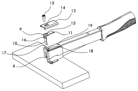
Fig.3 is a view in which essential parts of the invention is shown exploded;
Fig.4 is an enlarged view from line A-A in fig.1;
Fig.5 is a detail view showing the front part of the hammer tacker in which
view the driver is omitted and
Fig.6 shows a driver include in the present invention.
Preferred embodiment
Figure 1 discloses a hammer tacker 1, which comprises a handle 2 and a
magazine 3. The magazine comprises a magazine house 4 and a magazine
rail 5. The magazine rail is in known manner pivotally connected to the
magazine house, not disclosed in the figure. The connection makes it
possible to move the magazine rail in to and out of the magazine house in
the front end 6 of the magazine house, which movement is shown by the
double arrow P. The figure shows the tacker in a driving punch. The arrow
D in figure 1 and 2 indicates the direction of the punch. The tacker is in a
position. in which the rail 5 is in contact with a work piece 7 into which a


CA 02568330 2006-11-21

WO 2006/009496 PCT/SE2005/000834
3
staple 8, shown in figure 4, shall be driven. In the position shown in the
figure 1 is the rail out of the magazine house. Figure 2 shows the hammer
tacker in a position in which it has been moved further in the direction D
and in which position the rail has been moved into the magazine house
whereby, as will be described hereafter, a staple is pushed into the work
piece.
Figure 3 shows a driver 9 with a first driver blade 10 and a second driver
blade 11. A washer 12 and a fastening means 13 in the form of a screw are
also disclosed. The washer is provided with a first aperture 14 and the
driver blade 11 is provide with a second aperture 15 and the driver blade 10
is provided with a third aperture 16. From the figure is also disclosed a slot
17 arranged in the front end of the magazine and a fourth aperture 18. With
reference to figure 3 and 4 shall the attachment of the driver to the
magazine hereinafter be explained. Figure 4 is a view from line -A-A in
figure 1 and the parts facing the observer has been made transparent. To
attach the driver 9 to the magazine the driver blade 10 is moved down into
the slot 17, which slot is clearly shown in figure 5, to a position in which
the driver blade 11 contacts the outer side 19 of the magazine. The washer
12 is thereafter placed on the blade 11 and the screw 13 is placed through
the apertures 14,15 and 18 to a tightening engagement with a threaded hole
20 arranged in a block 21 which block is in known manner secured to the
inner side 22 of the magazine.

Figure 4 shows a staple row 23 placed on the rail 5. The row is pushed in
the forward direction by a feeding device 24. In the front end of the
magazine is an outlet opening 25 arranged and the front staple in the staple
row is pushed to that opening. When the hammer tacker in a driving punch
moves from the position shown in figurl to the position shown in figure 2
in which position the rail is in the magazine house will the blade 10 hit the
front staple 8 and force the staple into the work piece 7.

It is very simple to replace the driver blade if the blade due to use needs to
be replaced. To replace the driver blade one unscrew the washer 12 turn
around the driver 9 and mount the second driver blade 11 in the same way
as described above. This operation is very simple to do since the whole
operation is possible to do from the outer side of the magazine.


CA 02568330 2006-11-21

WO 2006/009496 PCT/SE2005/000834
4
Figure 6 discloses a driver which comprises a first driver blade 26 and a
second driver blade 27 which driver blade have different design which
could be valuable when used staples may have different design.
10
20
30

Representative Drawing
A single figure which represents the drawing illustrating the invention.
Administrative Status

For a clearer understanding of the status of the application/patent presented on this page, the site Disclaimer , as well as the definitions for Patent , Administrative Status , Maintenance Fee  and Payment History  should be consulted.

Administrative Status

Title Date
Forecasted Issue Date 2012-07-31
(86) PCT Filing Date 2005-06-02
(87) PCT Publication Date 2006-01-26
(85) National Entry 2006-11-21
Examination Requested 2008-06-17
(45) Issued 2012-07-31
Deemed Expired 2017-06-02

Abandonment History

There is no abandonment history.

Payment History

Fee Type Anniversary Year Due Date Amount Paid Paid Date
Registration of a document - section 124 $100.00 2006-11-21
Application Fee $400.00 2006-11-21
Maintenance Fee - Application - New Act 2 2007-06-04 $100.00 2007-03-30
Maintenance Fee - Application - New Act 3 2008-06-02 $100.00 2008-05-20
Request for Examination $800.00 2008-06-17
Maintenance Fee - Application - New Act 4 2009-06-02 $100.00 2009-05-20
Maintenance Fee - Application - New Act 5 2010-06-02 $200.00 2010-03-30
Maintenance Fee - Application - New Act 6 2011-06-02 $200.00 2011-05-25
Final Fee $300.00 2012-04-03
Maintenance Fee - Application - New Act 7 2012-06-04 $200.00 2012-05-25
Maintenance Fee - Patent - New Act 8 2013-06-03 $200.00 2013-05-08
Maintenance Fee - Patent - New Act 9 2014-06-02 $200.00 2014-05-15
Maintenance Fee - Patent - New Act 10 2015-06-02 $250.00 2015-05-13
Owners on Record

Note: Records showing the ownership history in alphabetical order.

Current Owners on Record
ISABERG RAPID AB
Past Owners on Record
EBBESSON, JAN
SOEDERHOLM, BJOERN
Past Owners that do not appear in the "Owners on Record" listing will appear in other documentation within the application.
Documents

To view selected files, please enter reCAPTCHA code :


To view images, click a link in the Document Description column. To download the documents, select one or more checkboxes in the first column and then click the "Download Selected in PDF format (Zip Archive)" or the "Download Selected as Single PDF" button.

List of published and non-published patent-specific documents on the CPD .

If you have any difficulty accessing content, you can call the Client Service Centre at 1-866-997-1936 or send them an e-mail at CIPO Client Service Centre.


Document
Description 
Date
(yyyy-mm-dd) 
Number of pages   Size of Image (KB) 
Claims 2006-11-21 1 32
Drawings 2006-11-21 5 64
Description 2006-11-21 4 156
Abstract 2006-11-21 1 61
Representative Drawing 2007-01-29 1 12
Cover Page 2007-01-30 1 46
Claims 2011-04-28 1 32
Description 2011-04-28 4 154
Cover Page 2012-07-09 2 53
Correspondence 2007-01-25 1 26
Assignment 2006-11-21 3 81
PCT 2006-11-21 3 80
Correspondence 2006-12-15 3 126
Fees 2007-03-30 1 39
Correspondence 2007-11-21 2 65
Fees 2008-05-20 1 39
PCT 2006-11-22 4 155
Prosecution-Amendment 2008-06-17 2 50
Fees 2009-05-20 1 40
PCT 2006-12-15 2 96
Fees 2010-03-30 1 40
Prosecution-Amendment 2010-10-28 3 125
Prosecution-Amendment 2011-04-28 8 329
Fees 2011-05-25 1 203
Prosecution-Amendment 2011-06-13 2 66
Prosecution-Amendment 2011-12-12 3 136
Correspondence 2012-04-03 2 49