Language selection

Search

Patent 2568425 Summary

Third-party information liability

Some of the information on this Web page has been provided by external sources. The Government of Canada is not responsible for the accuracy, reliability or currency of the information supplied by external sources. Users wishing to rely upon this information should consult directly with the source of the information. Content provided by external sources is not subject to official languages, privacy and accessibility requirements.

Claims and Abstract availability

Any discrepancies in the text and image of the Claims and Abstract are due to differing posting times. Text of the Claims and Abstract are posted:

  • At the time the application is open to public inspection;
  • At the time of issue of the patent (grant).
(12) Patent: (11) CA 2568425
(54) English Title: MEASURING PROBE
(54) French Title: SONDE DE MESURE
Status: Granted
Bibliographic Data
(51) International Patent Classification (IPC):
  • G01N 1/10 (2006.01)
  • G01N 27/26 (2006.01)
(72) Inventors :
  • NEYENS, GUIDO JACOBUS (Belgium)
(73) Owners :
  • HERAEUS ELECTRO-NITE INTERNATIONAL N.V. (Belgium)
(71) Applicants :
  • HERAEUS ELECTRO-NITE INTERNATIONAL N.V. (Belgium)
(74) Agent: MACRAE & CO.
(74) Associate agent:
(45) Issued: 2014-05-27
(22) Filed Date: 2006-11-20
(41) Open to Public Inspection: 2007-06-15
Examination requested: 2011-06-13
Availability of licence: N/A
(25) Language of filing: English

Patent Cooperation Treaty (PCT): No

(30) Application Priority Data:
Application No. Country/Territory Date
10 2005 060 493.5 Germany 2005-12-15

Abstracts

English Abstract

The invention relates to a measuring probe for measurement in molten metal having a measuring head arranged on an immersion end of a carrier tube and on which at least one sensor for determining a component of the molten metal and a bath contact are arranged, wherein the bath contact, viewed in the immersion direction, has a forward bath contact region with two surface areas arranged on opposite sides perpendicular to the immersion direction.


French Abstract

L'invention a trait à une sonde de mesure pour effectuer une mesure dans le métal fondu ayant une tête de mesure disposée sur une extrémité d'immersion d'un tube de transport et sur lequel au moins un capteur permettant de déterminer un composant du métal fondu et un contact de bain sont disposés. Le contact de bain visualisé dans la direction d'immersion comporte une région de contact de bain avant avec deux surfaces spécifiques disposées sur des côtés opposés perpendiculaires à la direction d'immersion.

Claims

Note: Claims are shown in the official language in which they were submitted.


Claims:

1. A measuring probe for measurement in molten metal, the probe comprising a
measuring
head arranged on an immersion end of a carrier tube, a bath contact and at
least one
sensor for determining a component of the molten metal being arranged on the
immersion
end, wherein the bath contact, viewed in an immersion direction, has a first
bath contact
region having two surface regions extending parallel to the immersion
direction lying on
opposite sides of the first bath contact and a second bath contact region
having two
surfaces regions extending parallel to the immersion direction and lying on
opposite sides
of the second bath contact, wherein a material stable in the molten metal is
arranged on the
opposite surface regions of the first bath contact region, wherein a material
stable in the
molten metal is arranged on at most only one of the opposite surface regions
of the second
bath contact region, and wherein at least one of the opposite surface regions
of the second
bath contact region is free of the stable material.
2. The measuring probe according to claim 1, wherein the bath contact extends
in the
immersion direction in front of an outer surface of the measuring head.
3. The measuring probe according to claim 1, wherein the arrangement of the
stable
material on the opposite surface regions of the first bath contact region
extends from
approximately adjacent a front edge of the first bath contact region back to a
front surface
of the measuring head.
4. The measuring probe according to claim 1, wherein the second bath contact
region and
the first bath contact region are arranged laterally adjacent each other in a
projection plane
arranged perpendicular to the immersion direction.
5. The measuring probe according to claim 1, wherein a front edge of the first
bath contact
region is arranged in the immersion direction at least 3 mm in front of a
front surface of the
measuring head.
6. The measuring probe according to claim 1, wherein the stable material is
foundry sand
or cement.


7. The measuring probe according to claim 1, wherein the stable material has
an outer
surface shaped in such a way as to lead gas bubbles in the molten metal away
from
exposed surface regions of the first bath contact region.
8. The measuring probe according to claim 1, wherein the second bath contact
region is
consumed first by contact with the molten metal, such that gas bubbles in the
molten metal
may be led away from a front edge of the first bath contact region along a
thus exposed
outer surface of the stable material.
9. The measuring probe according to claim 1, wherein the bath contact
comprises a metal
sheet.
10. The measuring probe according to claim 9, wherein the bath contact is bent
around an
axis approximately parallel to the immersion direction, and wherein one
portion of the metal
sheet is arranged within a silhouette formed by the bend.
11. The measuring probe according to claim 10, wherein the stable material
fills up the
silhouette.

6

Description

Note: Descriptions are shown in the official language in which they were submitted.


CA 02568425 2006-11-20
Measuring probe
The invention relates to a measuring probe for measurements in metal or slag
melts having a
measuring head, which is arranged on an immersion end of a carrier tube and on
which at least
one sensor for determining a component of the molten metal and a bath contact
are arranged,
wherein the bath contact, viewed in the immersion direction, has a forward
bath contact region
having two surface regions perpendicular to the immersion direction arranged
on opposite
sides.
Such measuring probes are known in many forms. For example, in DE 3541806 C1
or in DE 83
17 643 U1, measuring probes are known, on whose immersion side a bath contact
is arranged.
The bath contact is allocated to an electrochemical measuring cell. It is
constructed as a metal
rod. From DE 29 54 228 C2 and DE 79 25 016 U1, probes are known, which have a
tubular
structure and which each comprise a leg of a sensor. The bath contact can also
be used, in ad-
dition to the interaction with an electrochemical element, for measuring the
bath level of a mol-
ten metal, for example of the type where upon immersion of the bath contact
into the molten
metal, a circuit is closed and the level of the molten metal is determined
from the position of the
bath contact. The bath contact is usually made of steel and is destroyed
within the molten metal
after a short time.

CA 02568425 2013-07-24
,
f
An object of the present invention is to improve the known measuring probes
and, in
particular, the bath contact arrangements used in these probes and thus to
increase the
. reliability of the measuring probes.
According to the invention, a measuring probe is provided for measurement in
molten metal,
the probe comprising a measuring head arranged on an immersion end of a
carrier tube,
a bath contact and at least one sensor for determining a component of the
molten metal
being arranged on the immersion end. The bath contact, viewed in an immersion
direction,
has a first bath contact region having two surface regions extending parallel
to the
immersion direction lying on opposite sides of the first bath contact and a
second bath
contact region having two surfaces regions extending parallel to the immersion
direction and
lying on opposite sides of the second bath contact. A material stable in
molten iron or steel
is arranged on the opposite surface regions of the first bath contact region,
a material stable
in molten iron or steel is arranged on at most only one of the opposite
surface regions of the
second bath contact region, and at least one of the opposite surface regions
of the second
bath contact region is free of the stable material.
Because a material that is stable in molten iron or steel is arranged on the
opposing surface
regions of the first bath contact region and a material that is stable in
molten iron or steel
is arranged on a second bath contact region at most one surface region, with
the opposing
surface region of the second bath contact region being free of this material,
it is thereby
assured that the surface regions of the first bath contact region are better
protected from
the molten metal (for example, molten steel) than at least one of the surface
regions of the
second bath contact. This second bath contact region is thereby more exposed
to the
molten metal and therefore destroyed first, i.e., before the first bath
contact region.
In one embodiment of the invention, a stable material surface structure that
is inclined
relative to the cross section of the measuring head is constructed as an
approximately
conical shape to form a sort of hill or mound. The first bath contact region
is arranged
essentially embedded in the hill with its forward edge exposed at a forward
level in the
immersion direction. The second bath contact region is arranged outside the
stable material
surface, extending laterally (radially) and rearwardly (axially) from the
first bath contact
region. The surface of the stable material falls away toward the peripheral
edges of the bath
contact in the direction opposite to the immersion direction. Gas bubbles,
which form at the
front side of the bath contact upon immersion, cannot collect there, but
instead they are led
2

CA 02568425 2013-07-24
. .
away laterally rearwardly, so that the contact between the molten steel and
the bath contact
is not destroyed or interfered with by the bubbles.
Preferably, the bath contact extends, in the immersion direction, in front of
the outer surface
of the measuring head. The two-sided arrangement of the stable material
extends
expediently from the first bath contact region up to the measuring head. In
addition, the
second bath contact region and the first bath contact region are expediently
arranged
laterally adjacent to each other in a projection plane arranged perpendicular
to the
immersion direction. The first bath contact region is preferably arranged in
the immersion
direction such that its forward edge is at least 3 mm in front of the front
surface of the
measuring head, in order to better lead away the gas, because at this minimum
distance,
the slope/drop-off is sufficiently large.
The bath contact can be formed of a metal sheet. It can also be formed of a
metal rod, for
example as mentioned in the prior art described above, wherein then the stable
material has
an asymmetric arrangement around the metal rod. In this way, a first and a
second bath
contact region are also formed thereby. For the second bath contact region, it
is important
that the bath contact itself is not so well protected there from the molten
metal (molten iron
or steel) as the first bath contact region, so that it dissolves faster in the
second region,
while forming the described hill-like structure.
It is further advantageous that the bath contact formed, in particular from a
metal sheet, is
bent about an axis approximately parallel to the immersion direction, whereby
a portion of
the metal sheet is arranged within the silhouette formed by the bend. The
stable material
preferably fills up the silhouette and exposes portions of the bath contact on
the outer
periphery. Preferably, foundry sand or cement is used as the stable material.
In the following, embodiments of the invention are explained with reference to
the drawings.
Shown in the drawings are:
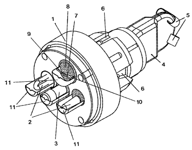
Fig. 1 the measuring head of a sample probe having a bath contact,
Fig. 2 a measuring head having another embodiment of a bath contact,
Fig. 3 a measuring head having another embodiment of a bath contact, and
Fig. 4 various bath contacts (Figs. 4a, 4b, 4c).
3

CA 02568425 2013-07-24
,
.
Figure 1 shows the measuring head 1 of a sample probe. Sensors 2 and also
the inlet tube
3 of a sample chamber 4 arranged on the rear end of the measuring head 1 are
arranged
= on the immersion end of the measuring head. The sample chamber 4 is a
typical two-shell
sample chamber, which is held together at its end with clamps 5. A carrier
tube (not shown
in the drawing) is placed on the rear end of the measuring head 1. Recesses 6
for
contacting the rear-side connections of the sensors 2 can be seen on the
measuring head
1. In addition, a bath contact 7 is arranged on the immersion end of the
measuring head 1.
In the embodiment of Figure 1 the bath contact 7 has the shape of an
approximately flat
metal sheet. It is embedded in refractory cement 8 and is surrounded by cement
8 in its first
bath contact region 9 (approximately in the middle) up to its forward end
edge. The second
bath contact region 10 is relatively unprotected from the molten steel when it
is immersed;
it is melted off. The conical shape of the cement 8 shown in Figure 1 allows
the discharge
of gases from the region of the end edge of the bath contact 7, so that a
faultless contacting
with the molten steel is possible. The bath contact 7, the sensors 2, and the
inlet tube 3 are
surrounded by protective caps 11.
In Figure 2 a similar measuring head 1 is shown. In contrast to the embodiment
according
to Figure 1, the bath contact 7 shown in Figure 2 has a meander-shaped
structure with a
first bath contact region approximately in the center of the bath contact 7
and a second bath
contact region on the outer periphery. Such a bath contact is shown in Figure
4c. It is
connected through a bore in the measuring head 1 to a contact line by means of
a contact
12 in a recess 6.
Figure 3 shows another embodiment of a bath contact 7, with the same
construction of the
measuring head 1. The bath contact 7 is constructed as a metal sheet bent into
a circle,
whose one end 13 is bent into the inside of the circle (cf. Figure 4b). The
contacting is
realized in the same manner in all of the shown embodiments. The first bath
contact region
9 is located approximately in the center of the circle formed by the bath
contact 7, while the
second bath contact region 10 is located on the outer periphery. The interior
of the circle is
filled up completely or nearly completely with foundry sand or cement.
Figure 4a shows another embodiment of the bath contact 7. Here, in contrast to
the
embodiment shown in Figure 4b, not only is a flat surface bent into the circle
interior, but
the sheet is also wound into the shape of a spiral spring.
4

Representative Drawing
A single figure which represents the drawing illustrating the invention.
Administrative Status

For a clearer understanding of the status of the application/patent presented on this page, the site Disclaimer , as well as the definitions for Patent , Administrative Status , Maintenance Fee  and Payment History  should be consulted.

Administrative Status

Title Date
Forecasted Issue Date 2014-05-27
(22) Filed 2006-11-20
(41) Open to Public Inspection 2007-06-15
Examination Requested 2011-06-13
(45) Issued 2014-05-27

Abandonment History

There is no abandonment history.

Maintenance Fee

Last Payment of $459.00 was received on 2021-11-08


 Upcoming maintenance fee amounts

Description Date Amount
Next Payment if small entity fee 2022-11-21 $253.00
Next Payment if standard fee 2022-11-21 $624.00

Note : If the full payment has not been received on or before the date indicated, a further fee may be required which may be one of the following

  • the reinstatement fee;
  • the late payment fee; or
  • additional fee to reverse deemed expiry.

Patent fees are adjusted on the 1st of January every year. The amounts above are the current amounts if received by December 31 of the current year.
Please refer to the CIPO Patent Fees web page to see all current fee amounts.

Payment History

Fee Type Anniversary Year Due Date Amount Paid Paid Date
Application Fee $400.00 2006-11-20
Registration of a document - section 124 $100.00 2007-01-08
Maintenance Fee - Application - New Act 2 2008-11-20 $100.00 2008-10-15
Maintenance Fee - Application - New Act 3 2009-11-20 $100.00 2009-10-21
Maintenance Fee - Application - New Act 4 2010-11-22 $100.00 2010-10-14
Request for Examination $800.00 2011-06-13
Maintenance Fee - Application - New Act 5 2011-11-21 $200.00 2011-10-13
Maintenance Fee - Application - New Act 6 2012-11-20 $200.00 2012-10-12
Maintenance Fee - Application - New Act 7 2013-11-20 $200.00 2013-10-16
Final Fee $300.00 2014-03-04
Maintenance Fee - Patent - New Act 8 2014-11-20 $200.00 2014-11-10
Maintenance Fee - Patent - New Act 9 2015-11-20 $200.00 2015-11-09
Maintenance Fee - Patent - New Act 10 2016-11-21 $250.00 2016-11-07
Maintenance Fee - Patent - New Act 11 2017-11-20 $250.00 2017-11-06
Maintenance Fee - Patent - New Act 12 2018-11-20 $250.00 2018-11-12
Maintenance Fee - Patent - New Act 13 2019-11-20 $250.00 2019-11-12
Maintenance Fee - Patent - New Act 14 2020-11-20 $250.00 2020-11-09
Maintenance Fee - Patent - New Act 15 2021-11-22 $459.00 2021-11-08
Owners on Record

Note: Records showing the ownership history in alphabetical order.

Current Owners on Record
HERAEUS ELECTRO-NITE INTERNATIONAL N.V.
Past Owners on Record
NEYENS, GUIDO JACOBUS
Past Owners that do not appear in the "Owners on Record" listing will appear in other documentation within the application.
Documents

To view selected files, please enter reCAPTCHA code :


To view images, click a link in the Document Description column. To download the documents, select one or more checkboxes in the first column and then click the "Download Selected in PDF format (Zip Archive)" or the "Download Selected as Single PDF" button.

List of published and non-published patent-specific documents on the CPD .

If you have any difficulty accessing content, you can call the Client Service Centre at 1-866-997-1936 or send them an e-mail at CIPO Client Service Centre.


Document
Description 
Date
(yyyy-mm-dd) 
Number of pages   Size of Image (KB) 
Abstract 2006-11-20 1 11
Description 2006-11-20 4 162
Claims 2006-11-20 2 50
Drawings 2006-11-20 4 67
Representative Drawing 2007-05-22 1 15
Cover Page 2007-06-11 1 39
Description 2013-07-24 4 201
Claims 2013-07-24 2 69
Cover Page 2014-04-30 1 41
Assignment 2007-01-08 2 64
Prosecution-Amendment 2011-07-21 1 37
Correspondence 2006-12-21 1 25
Assignment 2006-11-20 2 69
Prosecution-Amendment 2011-06-13 1 27
Prosecution-Amendment 2013-02-12 2 60
Correspondence 2014-03-04 1 30
Prosecution-Amendment 2013-07-24 7 289