Note: Descriptions are shown in the official language in which they were submitted.
CA 02568453 2006-11-27
PCT/EP2005/052330 - 1 -
2004P08371W0US
Description
High-temperature solid-electrolyte fuel cell and fuel cell
installation constructed using it
The invention relates to a high-temperature solid-electrolyte
fuel cell, in particular based on the tube or HPD concept. The
invention additionally also relates to an associated fuel cell
installation, which is constructed from fuel cells such as
these.
Specific fuel cells are known for power generation. In
particular, these are high-temperature fuel cells with a
solid-ceramic electrolyte, which are referred to as SOFC (Solid
Oxide Fuel Cell).
SOFC fuel cells are known in a planar and tubular form, the
latter of which is described in detail in VIK Reports "Fuel
cells", No. 214, November 1999, pages 49 et seqq. Planar fuel
cells can be produced in a folded form, in which case a fuel
cell installation having a stack structure is produced from a
large number of folded individual fuel cells in a monolithic
block (Fuel cells and Their Applications (VCH
Verlagsgesellschaft mbH 1996, E4, Fig. E20.5). It has not yet
been possible to produce fuel cells such as these.
In the case of a tubular fuel cell, individual fuel cell tubes
are electrically connected in series and/or in parallel in
groups. So-called HPD (High Power Density) fuel cells have been
developed from tubular fuel cells (literature reference: "The
Fuel Cell World (2004)" - Proceedings, pages 258-267), in which
the functional layers, in particular such as the solid-ceramic
electrolyte and the anode, are applied externally to a flat
sintered body which forms the cathode and has parallel
recesses. With its internal recesses, the cathode is used as an
CA 02568453 2006-11-27
PCT/EP2005/052330 - la -
2004P08371WOUS
air electrode, and the anode as a fuel electrode.
Interconnectors
CA 02568453 2006-11-27
PCT/EP2005/052330 - 2 -
2004P08371woUS
with nickel electrodes are provided on the flat face for
connection of a plurality of such HPD cells. In comparison to
individual tubular fuel cells, the HPD concept is more
powerful, more compact and in particular can be handled more
easily.
Furthermore, EP 0 320 087 B1 discloses a fuel cell arrangement,
for which a zigzag geometry of the supporting structure is
shown in figure 4. In particular, the description relates to
the intermediate structures for gas guidance. The document does
not describe the efficiency and power density of a fuel cell
arrangement such as this.
Against this background, the object of the invention is to
achieve a further performance improvement and increase in the
packing density of electrode-based solid-electrolyte fuel cells
based on a tubular concept or HPD concept, and to create an
associated fuel cell installation.
With regard to a single fuel cell, the object is achieved by
the features of patent claim 1. An associated fuel cell
installation is disclosed by the features of patent claim 15.
The respective developments are specified in the dependent
claims.
In the invention, the porous, electrically conductive material
forms the supporting structure for the electrochemically active
functional layers. Gas guidance channels are integrated in this
supporting structure. That part of the supporting structure
surface to which the functional layers are applied is
geometrically enlarged by shaping, so that this results in an
enlarged electrochemically active area.
Flat membranes composed of ceramic and in the case of which the
membranes form so-called multichannel elements are admittedly
already known from the "Handbuch der Keramik" (DVS Verlag GmbH
CA 02568453 2006-11-27
PCT/EP2005/052330 - 2a -
2004P08371W0US
Dusseldorf 2004 [Manual of Ceramics], Group IIK 2.1.4, Series
418. A corrugated structure with hollow channels is applied to
a planar flat body for this purpose. Membranes such as these
are used in particular as separating
CA 02568453 2006-11-27
PCT/EP2005/052330 - 3 -
2004P08371WOUS
tools for the filtration of liquids. Transfer to fuel cell
technology is not obvious since this relates to a purely
mechanical filtering application which has no electrochemical
converter functions whatsoever, in which case, in addition to
the boundary area size, electrical and ionic conductivities and
transport phenomena are also required, as well as electrical
connection technology for high temperatures between 900 and
1000 C.
Various embodiments are possible within the scope of the
invention. In detail, these are:
- the surface structure has a uniform shape in one
direction, that is to say in the pressing direction during
shaping. It can be extruded in this shape. Alternatively,
it can be composed of two extrudates/films.
- The surface structure can be further enlarged, for example
after shaping.
- The surface structure is shaped such that the
electrochemically active layers, that is to say the anode,
electrolyte, cathode, can be applied over the complete
area by coating processes or immersion processes, possibly
in conjunction with sintering steps for subsequent
compression. On the planar rear face, the functional
layers are interrupted only by a gas-tight interconnector
layer, which can likewise be applied using a coating
process or immersion process, in order to make contact
with the adjacent cell via suitable contact elements. This
thus results in fully electrochemically functional
individual cells.
- Widely differing surface structures are possible for the
invention. Examples of this are: corrugated sheet-metal
shape (delta), wedge-shaped, cuboid (so-called
CA 02568453 2006-11-27
PCT/EP2005/052330 - 3a -
2004P08371WOUS
"crenulations"), semicircular, meandering shape,
upwards/downwards staircases and combinations between
them.
- A supporting structure composed of anode material is
possible as an alternative to the supporting structure
composed of cathode material.
- The gas-permeable supporting structure can also be
electrochemically neutral, for example being composed of
porous metal or porous ceramic.
CA 02568453 2006-11-27
PCT/EP2005/052330 - 4 -
2004P08371W0US
The important factor is that, in the case of a fuel cell
installation according to the invention, a contact is made from
one individual cell to another individual cell by means of
flexible metallic moldings via the interconnector layers, in
order to form a stack. By way of example, the contact is made
from the anode of one cell to the cathode of the other cell via
the interconnector layer, for which purpose, for example, it is
possible to use metal mesh, meshes, knitted fabrics, felts,
composed, for example, of nickel, or nickel or chromium alloys,
as the contact element between the cells.
By way of example, especially for production of the
solid-electrolyte fuel cell as an SOFC, the supporting
structure is composed, for example, of doped LaCaMnO3
(cathode-supported) or Ni-YSZ-Cermet (anode-supported). The
electrolyte is composed, for example, of Y- or Sc-stabilized
zirconium oxide.
In the case of the invention, a fuel cell stack can be formed
by connection of the individual cells in series and/or in
parallel with a flexible contact molding, held together by
boards. In this case, the media can be guided in particular in
three different ways:
- parallel, that is to say the air on the inside and the
natural gas/fuel outside the cell (cathode-supported) or
vice versa (anode-supported),
- alternately "up/down" between individual cell channels
within the cell, which requires a gas guidance termination
at one cell end,
- "up/down" in two adjacent cells, which requires a cell
connector between the two cells.
In the case of the fuel cell installation according to the
invention, it is advantageous:
- that combustion of the residual gas across gaps is
possible if the cells are sealed at one end in an
CA 02568453 2006-11-27
PCT/EP2005/052330 - 4a -
2004P08371WOUS
air/gas-supply board without air deflection in the cell
("once through") and with an installation without any
seals at the other end, so that the cells are fixed only
at one end, so that
CA 02568453 2006-11-27
PCT/EP2005/052330 - 5 -
2004P08371WOUs
no mechanical longitudinal stresses are applied when
thermally loaded,
- if the cells in the boards are sealed at both ends, the
fuel and air circuits are separated, and this can be used,
for example, for hydrogen or carbon-dioxide separation.
With regard to the fuel cell installation according to the
invention:
- the fuel flow is guided either parallel (flow in the same
direction), parallel in opposite directions (opposing
flow) or at right angles (cross-flow) to the air,
- the supporting structure from one cell to the adjacent
cell is arranged in the same sense or offset in order to
form a stack.
For the purposes of the invention, an alternate "up/down" flow
between individual cell channels can advantageously be achieved
within the cell, with this being ensured by the gas guidance
termination at one cell end. In this context, WO 03/012907 Al
has admittedly already disclosed HPD fuel cells in which the
direction of the air flow is in each case reversed in pairs in
adjacent channels, after which the air is emitted at the side.
However, the solutions proposed there cannot be transferred to
the cell geometry as described here and structured on one side,
since this refers to plane-parallel flat cell structures.
The invention now provides the widest possible design options
with regard to the choice of the air guidance channels on the
one hand and the configuration of the fuel cell installation
with fuel cells stacked to form bundles, on the other hand. In
particular, the simple stacking capability of the individual
fuel cells resulting from the end fittings and their gas-tight
soldering to form a compact module is advantageous in
comparison to the prior art.
CA 02568453 2006-11-27
PCT/EP2005/052330 - 5a -
2004P08371WOUS
Further details and advantages of the invention will become
evident from the following description of the figures of
exemplary
CA 02568453 2006-11-27
PCT/EP2005/052330 - 6 -
2004P08371wous
embodiments on the basis of the drawing and in conjunction with
the patent claims. In the figures, in each case illustrated
schematically:
Figure 1 shows a detail from the novel fuel cell, in the form
of a section,
Figure 2b to Figure 2g show different alternatives for the
cross section of the fuel cell shown in figure 1,
with figure 2a illustrating the prior art,
Figure 3 shows a configuration for a stack with at least two
fuel cells connected via an interconnector, which
results in a periodic structure,
Figure 4 shows the configuration of a stack corresponding to
that in figure 3, but in which this results in a
shifted fuel cell structure,
Figure 5 shows a perspective illustration of a fuel cell with
internal means, arranged at the closed end, for air
deflection,
Figure 6 shows a first alternative to figure 5 with external
means for air deflection,
Figure 7 shows a second alternative to figure 5 with external
means connecting all of the channels,
Figure 8 shows a perspective illustration of the open end of a
fuel cell bundle composed of individual fuel cells as
shown in figures 5 to 7,
Figure 9 shows an overall view of a fuel cell bundle for
formation of a fuel cell installation,
Figure 10 shows a section through the molding at the open end
of the fuel cell bundle as shown in figure 9, with
means for air inlet and outlet, and
Figure 11 shows a plan view of the fuel cell bundle shown in
figure 9, from the inlet side.
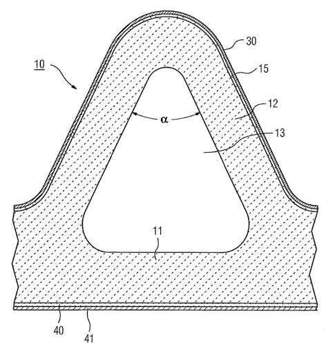
Figure 1 shows a detail of a single fuel cell. This comprises a
ceramic structure 10 with a flat base 11 and a structure 12
with a specific shape located on it. The structure may, for
CA 02568453 2006-11-27
PCT/EP2005/052330 - 6a -
2004P08371WOUS
example, be a wave or a triangular structure (delta), in
particular with the apex angle a of this structure being
CA 02568453 2006-11-27
PCT/EP2005/052330 - 7 -
2004P08371W0US
predetermined. For example, angles of 60, 45 or 30 may be
provided.
The base part 11 and the structure 12 may form a common unit,
and may be extruded jointly from the ceramic material. The two
parts may, however, also be produced separately, then being
placed one on top of the other.
The structures formed in this way each enclose an internal
volume 13 through which a medium can flow. In particular in
order to provide a cathode-supported fuel cell, the ceramic
structure provides the cathode and is composed either of
LaCaMnO3 or of LaCa(Sr)Mn03, with the further functional layers
being applied to the upper face of the structure. In
particular, this is the solid electrolyte 15 composed of Y- or
Sc-stabilized zirconium oxide and the anode 30 composed, for
example, of Ni-YSZ Cermet, with these specific ceramic
materials being known from the prior art.
An interconnector strip 40 is located on the lower face, with
nickel plating 41 for connection of a first fuel cell to a
second fuel cell, in which case, in this context, reference is
also made to the description of figure 3, further below.
One major feature of the structure shown in figure 1 (delta) is
that the electrochemically active surface is enlarged in
comparison to the known HPD fuel cell with a flat surface. This
is achieved by the wave structure or triangular structure as
shown in figure 1, in which case the flanks can be stepped in
order to additionally enlarge the surface.
Figures 2b to 2g show various suitable shapes: for comparison,
figure 2a shows an elementary element of an HPD fuel cell
according to the prior art. In addition to the wave shape shown
in figure 2b, a triangular shape can also be specified, as
shown in figure 2c. In addition,
, = CA 02568453 2006-11-27
PCT/EP2005/052330 - 8 -
2004P08371WOUS
quadrilateral shapes as shown in figure 2d are also possible,
which form so-called "crenulations". Further shapes are
possible with a continuously curved surface, in particular in
the form of an oval 4 as shown in figure 2e, or a stepped
triangle as shown in figure 2f. A quadrilateral shape may also
be in the form of a meander as shown in figure 2g. Further
shapes are possible, for example, with an angle and undercut.
All of the cases shown in figure 2b to figure 2g result in a
considerably enlarged active surface area in comparison to the
active surface area of the prior art as shown in figure 2a.
Figure 3 shows a stack formed by two ceramic structures as
shown in figure 1, which each form a single fuel cell, with the
stacking being carried out in the same phase. A flexible
knitted fabric 50, composed in particular of nickel, is located
between the two ceramic structures 10, 10' and makes the
electrical contact between the nickel plating 41 on the
interconnector strip 40 and the anode 30, which are not shown
in detail in figure 3.
The interconnector 40 is formed in a known manner from
electron-conducting lanthanum chromate, which has been found to
be suitable for long-term applications and, in particular, has
also been found to be resistant to oxidation. In order to
compensate for mechanical stresses, the interconnector 40 makes
an electrically conductive contact within the adjacent cell via
the contact body 50, which is composed of metal mesh, woven
fabric or else is formed by a felt composed of nickel.
A large number of individual fuel cells 10, 10', ... form a
stack, with side boards being provided for holding purposes. A
stack such as this forms the core of a complete fuel cell
installation. In this case, the fuel gas flows around the stack
in a container, without any gas guidance structures.
= = CA 02568453 2006-11-27
PCT/EP2005/052330 - 9 -
2004P08371WOUS
It may be worthwhile in each case offsetting two individual
fuel cells with respect to one another by half the period
structure with respect to one another in order to form a stack,
in order to distribute the contact points between the fuel
cells which are stacked one on top of the other. This is
illustrated in figure 4, for the fuel cells 20, 20', .... In
this case, nothing is changed with regard to the method of
operation of the complete stack.
Particularly in the case of the arrangement shown in figure 4,
mechanical stresses are avoided in comparison to monolithic or
planar fuel cells. The metallic contact elements may also be
mats, chords, metal mesh, stamped/embossed moldings or
combinations/mixed forms.
The following table shows a performance comparison of previous
cell types (tube, HPD4, HPD5, HPD10, HPD11) with cell types
delta 9 - 63 and delta 9 - 78 according to the invention. In
this case, the tubular "tube" cell which has been used until
now has an active length of 150 cm, while all the HPD and delta
cells have an active length of 50 cm.
Table:
Tube HPD4 HPD5 HPD10 HPD11 Delta 9 Delta 9
150 cm 50 cm 50 cm 50 cm 50 cm 63 78
50 cm 50 cm
Number 40 57 28 26 25 16 14
of
cells
per 5
kW
Cell 126 88 177 191 198 321 362
power
(W)
Power 113 191 158 217 275 308 332
to
weight
ratio
(W/kg)
CA 02568453 2006-11-27
PCT/EP2005/052330 - 9a -
2004P08371W0US
Power 136 297 262 394 447 542 563
to
volume
ratio
(kW /m3 )
The rows in the table show the number of cells per 5 kW, the
cell power and, as major comparison criteria, the power to
weight ratio and the power to volume ratio.
CA 02568453 2006-11-27
PCT/EP2005/052330 - 10 -
2004P08371WOUS
The prior art discloses the formation of the cells as
individual tubes or as an HPD cell with four, five, ten or
eleven hollow channels. The embodiments according to the
invention are listed in the last two columns, and are compared
with the prior art.
The previous development has already shown that the replacement
of the tubes by HPD cells leads to smaller components, and that
this increases the power to weight ratio and/or the power to
volume ratio. Beyond this, the new technology delta 9 further
increases the power yield.
Overall, the table shows a considerable power increase for the
fuel cells according to the invention. Since the effort for
production of cells such as these as a result of
further-developed extrusion and coating technologies is
essentially the same as in the case of the previous cells, this
results in a particularly advantageous price to power ratio for
fuel cells.
Figures 5 to 8 show a delta fuel cell 100. This comprises a
ceramic structure with a planar base 101 and a structure 102
with a specific shape located on it. By way of example, the
structure 102 may be a wave structure or a triangular
structure, in which case, in particular, the apex angle a of
this structure is predetermined. For example, angles a of 60,
45 or 30 may be predetermined.
The base part 101 and the structure 102 form a common unit, and
are extruded jointly from a ceramic material which is suitable
for SOFC fuel cells.
One major feature of the structure shown in figure 1 and figure
is that the electrochemically active surface is enlarged in
comparison to the known HPD fuel cell with a planar surface.
This is achieved, for example, with a wave or
CA 02568453 2006-11-27
PCT/EP2005/052330 - 11 -
2004P08371W0US
triangular structure, in which case the flanks may be stepped
in order to additionally increase the surface area.
Delta fuel cells as described above can be stacked to form a
fuel cell installation. The insertion of a complementary
structure into the respective end areas of the fuel cell allows
a fuel cell bundle to be formed which can be stacked, can be
sealed externally and has improved gas connection means, in
particular defined gas inlets/outlets. This thus results in
individual modules for the fuel cell installation.
In the case of the fuel cell described here, the air is carried
in the interior of the channels, and the fuel gas is carried in
the open channels on the outside of the cells. In this case,
the air is in general introduced in every alternate channel
from one end of the fuel cell in each case and, after passing
through the entire length of the fuel cell, is deflected and is
passed back on a parallel path. This means that the air must be
deflected through 180 at the end of the fuel cell.
The air is advantageously passed out at the side, at the open
end. This means that, in this case, the air is deflected such
that the channels with the fed-back air are opened, and meet a
connecting channel of the adjacent cell.
One major aspect initially is the air deflection at the closed
end of the fuel cell. Various alternatives are possible for
this purpose, which will be described in detail with reference
to figures 5 to 7.
Figure 5 shows one such delta fuel cell with an even number of
flow channels 111, 111', ..., for example with eight channels.
In this case, two adjacent channels are in each case associated
with one another, that is to say the air is carried in the
first channel from the open end to the closed
CA 02568453 2006-11-27
PCT/EP2005/052330 - 12 -
2004P08371WOUS
end, where it is deflected to the adjacent channel, and is fed
back in this channel.
If the delta fuel cell is extruded in a suitable manner with
thickened connecting webs in every alternate sink and is
sufficiently robust, two adjacent channels 111, 111' can be
connected in a simple manner by a transverse channel 112. This
means that, of the eight fuel cell channels in figure 2, two
adjacent channels each have the transverse channel 112 at the
closed end. The entire arrangement is closed at the end by a
plate 110.
As an alternative to figure 5, a cell with uniform recesses and
any desired number of channels can be chosen. As shown in
figure 6, eight channels 111, 111', ... are once again provided
in the fuel cell 100 with a cover 110. In this case, however, a
molding 120, 120' is introduced into each recess or into every
alternate recess in the wave structure. The moldings 120, 120',
, each have a transverse channel 121, 121', .... Associated
transverse channels 121, 121' in the individual fuel cell
channels 111, 111', ... are in this case used to provide the
connection to the second air guidance channel 101 from the
first air guidance channel 101 via the first channel 121', the
transverse channel 113 and a second channel 121'.
The two examples shown in figure 5 and figure 6 have an even
number of air guidance channels. This results in a system
eminent connection, in that the air is guided in the opposite
direction in the two edge channels of the delta fuel cell.
In a further alternative embodiment shown in figure 7, a
continuous transverse channel 115 is introduced over the end of
the entire delta fuel cell 100. This means that all eight air
guidance channels 111 to 111', ... are connected to one another
for fluid-flow purposes. When air is applied to the individual
channels from the input side, it is thus possible
CA 02568453 2006-11-27
PCT/EP2005/052330 - 13 -
2004P08371W0US
for the air to flow out via one or more channels and to flow
back in any desired number of other channels. In this case,
once again, a cover 110 is provided, as well as a complementary
molding 130.
If a part is inserted into each recess in the fuel cell shown
in figure 6, a continuous transverse channel is also possible
in this embodiment. From the production engineering point of
view, the parts are composed of the same basic material and are
inserted as separate green products, and are sintered together
with the fuel cell structure.
As can be seen in figure 8, a complementary part 40 is likewise
placed on the wave structure in the input area of the fuel cell
100. In figure 8, it is advantageous for the air to be supplied
from underneath, and for the air to be carried away at the side
through openings 141, 141', ..., as discrete outlets. The fuel
cell 100 is closed at the bottom by a cover 150 which, as a
base plate, also covers the closed complementary part 140.
Figure 9 shows a fuel cell bundle comprising three delta fuel
cells 100, 100', 100 with an air inlet/outlet as shown in
figure 8 and with air deflection as shown in figure 7. In this
case, the fuel cells are stacked in the same phase to form a
stack through which a fuel gas can flow in a container without
gas guidance structures. A stack such as this forms the core of
a fuel cell installation.
The individual delta fuel cells 100, 100', 100'' in the
exemplary embodiment illustrated in figure 9 each have nine
channels, so that the flow conditions are the same at both
edges, with suitable flow deflection as shown in figure 7.
In the arrangement shown in figure 9, the air clearly flows
upwards from the bottom upwards ("up"), is deflected in the
CA 02568453 2006-11-27
PCT/EP2005/052330 - 14 -
2004P08371WOUS
end part, and then flows from the top downwards ("down"), with
the air flowing out at the side at the lower end.
In principle, the arrangement of the fuel cell bundle can also
be oriented in the opposite sense. A horizontally aligned
arrangement is also possible.
Figure 10 shows a cross section through the bundle 125 on the
plane of the side air outlets. As can be seen, in the
individual delta fuel cells 100, 100', 100'', the air guidance
channels lllik (i=1-m, k=1-n) of every alternate column of the
fuel cells 100, 100', 100'' which are stacked in the same phase
are each connected to one another by a transverse channel 245,
which leads to the external outlets 141, 141', . . . In this
illustration, the inlets are connected in a singular form to
the individual air inlet channels.
As can be seen in figure 10, a plan view of the lower cover
shows individual inlets 241, which correspond with the open air
guidance channels 111i+l,k.
The end parts or stacked parts in figure 9 are connected to one
another in a gas-tight manner by means of a glass solder, and
form compact connecting blocks. These areas, which are inactive
for the fuel-cell function, are covered with the electrolyte of
the active fuel cells, as is indicated by the layer 215 in
figure 10.
Corresponding to figure 9, a stackable arrangement of a fuel
cell bundle for a fuel cell installation is created overall
with the connecting blocks 230 and 240. There is sufficient
space between the connecting blocks in order to electrically
connect the individual delta fuel cells in a known manner by
means of a felt or mesh composed of nickel (Ni) or a Ni-Cr
alloy.
CA 02568453 2006-11-27
PCT/EP2005/052330 - 14a -
2004PO8371WOUS
If the fuel cell installation is configured as shown in figures
9 to 11, it is particularly advantageous for compact supporting
parts
CA 02568453 2006-11-27
PCT/EP2005/052330 - 15 -
2004P08371W0US
to be formed at each of the ends of the fuel cells. These parts
comprise the inactive areas of the individual delta fuel cells
and the complementary parts for the wave structure, in which
case, as already mentioned, the individual fuel cells are
connected to one another by means of the glass solder in this
area, and the compact assembly is in each case surrounded, as a
connecting block, by the electrolyte film.
The arrangements described above apply to all known variants of
supporting structures, to be precise for cathode-supported,
anode-supported or neutral structures. In addition to the
described wave or triangular geometry (delta) of the fuel
cells, the described features also apply to other geometries,
as have been described. The important factor is the enlargement
of the electrochemically active surface area and the specific
deflection of the air flow in the air guidance channels by
suitable means. These means result in a direction reversal at
the cell end, in particular through 180 , or at the outlet, in
particular through 90 .