Note: Descriptions are shown in the official language in which they were submitted.
CA 02568757 2006-11-17
WO 2005/113201 PCT/IB2005/001377
ANTI-TAMPER RING EXTRACTION TOOL
Field of the Invention
The present invention relates to an anti-tamper ring extraction tool for
removing an
anti-tamper ring from a valve assembly of an alcohol beverage container.
Background of the Invention
It is lcnown to contain alcohol and beer in a container or a keg. In the case
of a beer
keg, pressure is applied to a beer containing bag housed within the keg to
dispense beer the
through a valve body assembly from the bag contained in the keg.
It is known to utilize an anti-tamper ring to prevent removal of the valve
body
assembly from the keg or to provide a visual indication that someone has
tampered with the
valve body assembly. The anti-tainper ring is usually seated around the
outside of the valve
body assembly and covers the valve body assembly and keg shoulder surrounding
the valve
body assembly. Further, the anti-tamper ring has been used to close a relief
airway through
the valve body assembly. When the anti-tamper ring is displaced from the
relief airway or
removed from the container, pressurized air between the bag and the keg inner
liner wall
safely bleeds through the relief airway.
By its very purpose, the anti-tamper ring is not easy to remove from the keg
and valve
body assembly. However, the anti-tainper ring needs to be reinoved when the
keg is recycled
for refilling. Once the anti-tamper ring is removed, the valve body assembly
and the bag can
be removed from the keg. Then, the bag is disposed with. The valve body
assembly and the
keg are cleaned and re-used. During this procedure, it is important that the
valve body
assembly not be damaged so that this part can be recycled. Accordingly, there
is a need to
provide a mechanism for removing an anti-tamper ring from the valve body
assembly and the
keg during recycling that is not subject to damaging the valve body assembly.
Summary of the Invention
The present invention relates to a tool for extracting an anti-tamper ring
from a valve
assembly having an axis. The tool has a plurality of claws that are adapted to
be axially
spaced about the axis. Each of the claws has at least one claw tip. An
actuating mechanism
moveably supports the claws for movement from at least a first to a second
position. The
-1-
CONFIRMATION COPY
CA 02568757 2006-11-17
WO 2005/113201 PCT/IB2005/001377
claws in the first position are adapted to have at least one claw tip resting
on the anti-tamper
ring. The claws when moved into the second position are adapted to have the at
least one
claw tip move radially inward towards the axis of the valve assembly and
vertically upward
relative to the first position to engage and lift the anti-tamper ring from
the valve assembly.
It should be understood that in the practice of the present invention at least
two claws
are required in order to provide proper leverage to pull or extract the anti-
tamper ring from
the valve assembly. Alternatively, three claws could be spaced at equal angles
axially about
the axis of the valve body assembly. In the preferred construction, four claws
are utilized
spaced equally around the valve body assembly at intervals of 90 degrees.
In accordance with the present invention, it is fu.rther contemplated that the
actuating
mechanism may be adapted to move the claws from the second position into a
third position.
In the third position, the at least one claw tip is moved radially outward
relative to the second
position so as to release the anti-tamper ring from the claws.
In the preferred construction, the claws have a leading claw tip and a
trailing claw tip
radially offset from each other. At least the leading claw tip rests on the
anti-tamper ring
when in the.first position. When in the second position, the leading claw tip
pierces the anti-
tamper ring and the trailing claw tip at least engages the anti-tamper ring.
In the preferred construction, it is envisaged that the actuating mechanism
comprises a
cross beain support may be moveable horizontally in downward and upward
strokes. The
cross beani support supports four link arms each having a first link end
portion that is
pivotally connected a beam end portion of the cross beam support. Each of the
four link arms
has a second linlc end portion that is pivotally connected to a first claw end
portion of the
claws. Each of the claws has a mid pivot point about which the claw tips
rotate to bring the
claws into the first position as a cross beam support moves in a downward
stroke. The claws
are brought into a second position as the cross beam support moves in an
upward stroke. It is
fiu=ther envisaged that the claws may be moved vertically relative to the
cross beam support
to effect movement of the claws from the second position to the third
position. To effect this
movement it is envisaged that additional means in the form of a cylinder
actuated member
may be attached to the mid pivot point to move the claws from the second
position to the
third position.
-2-
CA 02568757 2006-11-17
WO 2005/113201 PCT/IB2005/001377
Brief Description of the Drawings
For a better uiiderstanding of the nature and objects of the present invention
reference
may be had to the accompanying diagrammatic drawing in which:
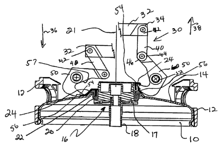
Figure 1 is a split sectional view of anti-tamper ring extraction tool of the
present
invention showing the claws of the tool in two positions.
Detailed Description of the Invention
Referring to Figure 1 there is shown an upper portion of an alcohol container
or beer
keg 10 having a chime 12 .attached thereto. The beer keg 10 has a top wall 14.
The top wall
14 has a central opening for receiving a valve body assembly 16.
The valve"body assembly 16 has a hub 17 to which is connected a central spear
18
that extends into a bag (not shown). Alcohol or beer passes through a valve
(not shown) in
the hub 17 and through the spear 18 into and out of the keg 10. The hub 17 of
the valve body
asseinbly 16 further includes additional valves (not shown) used to pressurize
the bag and the
inside of the keg 10. The valve assembly 16 is shown oriented along a vertical
extending axis
21.
The valve body assembly 16 has a bung 20 that interconnects the hub 17 with
the
edge 22 of the central opening of the top surface 14 of the keg 10.
Referring to the left side of Figure 1, an anti-tamper ring 24 is shown
mounted to the
left side of the valve body assembly 16. Anti-tamper ring 24 is seated
position with the valve
body assembly 16. In this seated position, the anti-tamper ring 24 covers a
portion of the top
keg surface 14 and part of the valve body assembly 16.
It should be understood that Figure 1 illustrates the anti-tamper ring 24 in
its seated
position on the.left side of Figure 1 and shows the anti-tamper ring 24
extracted from the
valve body assembly 16 on the right side of Figure 1. This split perspective
view is utilized
to illustrate both seating and extraction of the anti-tainper ring 24. In
practice, the anti-
tamper ring 24 is extracted at least substantially unifonnly from the valve
body assembly 16.
Referring to Figure 1 there is shown a too130 for the removal of the anti-
tamper ring
24 from the valve body assembly 16. The tool 30 comprises a pair of cross beam
supports
32, extending orthogonally relative to each other and intersecting at a
midpoint. Only one of
the cross beam supports 32 is shown in Figure 1. It should be understood that
in practice the
left hand and right hand sides of Figure 1 of the cross beam support 32 are in
fact one beam
shown at two different positions. The cross beam support 32 has four beam end
portions 34
-3-
CA 02568757 2006-11-17
WO 2005/113201 PCT/IB2005/001377
of which only 2 are shown in Figure 1. The cross beam 32 is moveable in a
horizontal
downward stroke indicated by arrow 36 and an upward horizontal stroke
indicated by arrow
38.
The extraction tool further includes four linlc arms 40 which are pivotally
connected at
a first linlc end portion 42 to a corresponding first beain end portion 34.
Each of the four link
anns 40 has a second linlc end portion 44 which is pivotally connected with a
claw end
portion 46 of claws 50. Each of the claws 50 has a mid pivot point 52 and a
pair of claw tips
54 and 56. The claws 50 are shaped with a concave-like surface 57 that faces
towards axis 21
and extends between claw end portion 46 and claw tip 54.
In accordance with the present invention, the claws 50 are adapted to be
axially
spaced about axis 21. A tool actuating mechanism comprising the cross beams 34
and the
four link arms 40 together witli appropriate hydraulic cylinders (not shown)
connected to the
cross beam and to the mid pivot points 52 movably support the claws 50 between
at least a
first position shown on the left of Figure 1 and a second position on the
right of Figure 1.
In the first position shown on the right of Figure 1, the claws 50 are adapted
to have
the leading claw tip 54 resting on top of the anti-tamper ring 24. A trailing
claw tip 56 is
shown radially displaced outward from claw tip 54 and is supported above and
in non-
contacting relation with the top surface of the keg 14. When the cross beam
supports 32 are
moved in an upward stroke indicated by arrow 38, intermediate link arm 40
pivots relative to
the cross beam member 32 causing the claw 50 to pivot about its mid pivot
point 52 so that
the claw tips 54 and 56 move radially inwards towards the axis 21 of the valve
body
assembly 16. Also with this pivoting movement, the claw tips 54 and 56 move
vertically
upward relative to the first position shown on the left of the drawing so as
to engage and lift
the anti-tamper ring 24 from the valve assembly 16. In the second position
shown in the right
of Figure 1, the leading claw tip 54 has pierced the anti-tamper ring 24. The
trailing tip 56 is
engages and grasps the anti-tamper ring 24.
The upward stroke, as indicated by arrow 38, of the actuating mechanism
continues
until the anti-tamper ring 24 clears the top portion of the valve body
assembly 16. At this
time, the cross beam 32 stops its upward motion and an actuating piston
cylinder (not shown)
connected to the mid point 52 of the claw 50 continues to raise the claw 50.
As a result of
this, the claw 50 moves into a position relative to the cross beam 32 similar
to that shown on
the left hand side of Figure 1. In other words, the cross beam 32 is
positioned substantially at
its location shown on the right hand side of Figure 1 with the link 40 and the
claw 50 in a
position shown similar to that on the right hand side of Figure 1. When moving
from the
-4-
CA 02568757 2006-11-17
WO 2005/113201 PCT/IB2005/001377
second position to the third position the claws 50 rotate about pivot points
52 radially
outward so that the claw tips 54 and 56 move radially outward relative to the
positions shown
in Figure 2 to thereby release the anti-tainper ring 24 from the claws 50.
Now, the too130 is
ready to move in a downward stroke 36 once a keg 10 has been positioned
beneath the tool
30 having an anti-tamper ring 24 to be removed.
The use of the tool 30 of the present invention allows for the simple
extraction of an
anti-tamper ring 24 normally locked in place with the valve body assembly 16.
The tool 30
effectively extracts the anti-tamper ring 24, does not come into contact with
the top surface
14 of the lceg 10 and does not come into direct contact with the valve body
assembly 16.
Consequently, the tool does not damage the valve body assembly 16 nor mar the
top surface
14 of the keg 10 during anti-tamper ring extraction.
-5-