Note: Descriptions are shown in the official language in which they were submitted.
CA 02568899 2006-12-04
WO 2005/120101 PCT/CA2005/000868
-1-
AUTONOMOUS INFRASTRUCTURE WIRELESS NETWORKS
FIELD OF INVENTION
This invention relates in general to wireless communication networlc
technology.
This invention relates in particular to cellular network systems and
architectures; and
methods for deploying cellular networks.
BACKGROUND OF THE INVENTION
A wireless communication network generally consists of various transceivers
(transmitters and receivers) that achieve inter-communication by means of the
emission of electromagnetic waves. These transceivers, which are also referred
to as
radio access equipment, exist in different physical sizes and have different
transmission/reception capabilities that are characterized by factors such as
maximum
signal transmission power levels, information transmission bit rate
capability, ability
to transmit or receive signals to/from a number of other transceivers, and
supported
frequency bands of operation. In terms of current systems, examples of this
type of
radio access equipment consists of small portable terminals such as cellular
phones
with multiple band capability or personal digital assistants with wireless
access
capability, portable radios with multi-band capability and higher power tlian
cellular
terminals, cellular base stations, wireless LAN access points, wireless cards
installed
in portable computers, etc.
Such radio access equipment can be classified into two categories: i)
equipment that is
shared by multiple users, i.e. undertalces communication to multiple users in
different
locations, and ii) equipment that is dedicated to a particular user. Shared
equipment
forms part of what is generally referred to as the networlc infrastructure.
This
equipment, or infi-astructure, is deployed throughout a geographical service
area.
Ofiher transceivers that venture into this area can communicate with the
infrastructure
equipment in a manner that is luiown.
CA 02568899 2006-12-04
WO 2005/120101 PCT/CA2005/000868
-2-
Wireless networks can be classified in terms of the types of transceivers that
they
incorporate. These networks can be classified as i) infrastructure-only, ii)
infrastructure-terminal, and iii) terminal-only. Microwave point-to-point
networks are
examples of i) since there are no terminals, cellular networks are examples of
ii) since
they include base stations and terminals, and ad-hoc networks such as WiFi
(IEEE
802.11 b & 802.11 a) operated in ad-hoc mode are examples of iii).
Considering networlcs with infrastructure, in the most common case individual
infrastructure elements are placed in fixed locations and connected to a fixed
wire-line
network such as a public switched telephone network (PSTN), a cable TV network
(CATV), a power-line communication network, or to a local area networlc (e.g.
Ethernet) that is connected to the Internet. An example is the case of
cellular networks
where the wireless transceiver that forms part of the infrastructure is ealled
a radio
base-station. In the case of local area networlcs czu7=ent examples are access
points for
wireless LANs. These access points form gateways from a wireless LAN to a
fixed
network.
The first category of equipment in the above (shared by multiple users) is
typically
referred to as networlc equipment, and the second category is called terminal
equipment. The network equipment is however not required to be fixed, and it
is
possible that future networlcs niay have mobile base stations. In fact one
example of
such mobile base stations is base stations that are installed in moving
platforms such
as trains, buses, ships, and airplanes. One characteristic of networlc
equipment versus
terminal equipment is that typically it has a higher cost, is physically
bigger, and
typically has the capability to provide a connection to a number of terminals
simultaneously.
The nattu-e of current networlc infi=astructure is that it must be deployed
(or installed)
using a non-trivial procedure, and often by a specialist, in order for a
network to exist.
We may classify the resulting networlcs into two categories, those that are
installed
and meant for the use of a private company, institution, (or household), where
the set
CA 02568899 2006-12-04
WO 2005/120101 PCT/CA2005/000868
-3-
of users is restricted to a specific group, and those that are meant for the
use of any
member of the general public who undertakes a.service contract with the so-
called
network operating company. Networks of the former type are called private
networks,
whereas networks of the second type are called public networks.
Currently cellular networlcs are the prime examples of wireless public
networks,
whereas local area networks, such as WiFi, set up in private companies or
homes, are
prime examples of private networks in the sense that they are meant to
interconnect
with a limited specific set of terminals. WiFi networks set-up to provide the
so-called
hot-spot service are examples of public networl<s. The main difference between
cellular networks and hot-spot networks based on WiFi is that in the case of
cellular
iietworks, the network lias a very wide coverage, and in many cases it covers
whole
countries. Hot-spot networks on the other hand cover specific limited
locations and in
some cases a number of these locations are interconnected by the same fixed
network
and managed by a single network operating company to form a single network
with
non-contiguous coverage.
As mentioned above, networks can be categorized into those that have an
infrastructure coniponent and those that are purely ad-hoc networks (terminal-
only).
The design of wireless networks with infrastructure components and mobile
terininals
has its roots in telephony, where the goal is to provide telephone service
anywhere in
a large coverage area and in effect introduce mobility to telephone networks.
On the
other hand, the design of purely ad-hoc networks has its roots in military
communications that itself gave rise to the Internet. The design of
communication
networks is typically carried out using an approach that divides the overall
task into a
set of taslcs that address issues at different levels of abstraction. There is
a well lcnown
OSI 7-layer reference model that is used. In the case of wireless networks the
physical
layer refers to the level of abstraction, in this model, that addresses issues
of
modulation, ei-ror control coding, multiple access, and many other issues
including
power control and hand-offs.
CA 02568899 2006-12-04
WO 2005/120101 PCT/CA2005/000868
-4-
Currently there are two main classes of wireless networles that are widely
used: i) the
cellular networlcs that are based on the various physical layer designs such
as AMPS,
IS-136, PDC, GSM, IS-95 (CDMA or "Code Division Multiple Access"),
CDMA2000, and WCDMA, TD-SCDMA, and ii) the wireless LANs that are based
on the physical layers IEEE802.11b,a,g. The different cellular standards have
been
classified into generations and currently we are at the third generation. As a
result we
will refer to all these cellular network technologies as 3G - since this is
the current
status of this line of technologies. In the case of wireless LANs the main
physical
layer currently in use is IEEE802.11b and IEEE802.11a and is referred to as
WiFi.
The physical layers for 3G and WiFi are significantly different. The main
reason for
this difference is that the design of the WiFi physical layer was based mostly
on the
purely ad-hoc networking concept, whereas the design of 3G and all its
predecessors
was based on a network with infrastructure where a set of somewhat regularly
placed
base-stations provide coverage over a wide geographical area. However, as a
result of
wireless industry circumstances, the success of the 3G system in providing
Internet
access has been less than expected. On the other 11and, the wii-eless Internet
access
based on the WiFi air interface has been successful not in the purely ad-hoc
mode but
in the infrastructure mode, i.e. in a mode where an access point that is
attached to the
Internet is employed. In a sense we have the WiFi network succeeding in an
area for
which the 3G air interface was designed, i.e. as an infrastructure networlc to
access the,
Internet albeit with limited coverage.
In spite of the different design eriteria, both the 3G and WiFi technologies
are
generally being used mostly as infrastructure for access by terminals. For the
sake of
clarity, "terminal" in this disclosure generally refers to a network-connected
device
associated with a user including a cell pllone, llandheld device, personal
computer, or
other computerized devices capable of wireless network connectivity. The key
difference between these two technologies is the manner in which they are
being
deployed. The nature of deployment of a wireless network infi-astructure is an
important issue. In the past we have had a tremendous degree of emphasis on
the
capacity per unit base station as the key issue for the design of different
air interface
CA 02568899 2006-12-04
WO 2005/120101 PCT/CA2005/000868
-5-
technologies. This capacity can typically be measured in terms of the mnnber
of voice
users that a base station can support per MHz of spectrum allocated, or the
aggregate
bit rate per base station per MHz of spectrum in supporting a number of term-
inals. A
huge degree of development in the different generations of cellular systems
has been
guided by this basic principle of maximizing the spectral efficiency per base
station.
These base stations are typically costly to install. This is because they are
usually
meant to cover a large service area and require a comparatively large power
amplifier
that is generally expensive. In addition, the installatioii of the
transmitting antennas
generally requires the rental of private facilities at the top of private
buildings. Also,
selection of a site to install a base station generally requires a very
carefitl study of
signal propagation and signal coverage by RF networlc planning engineers.
These
engineers represent perhaps the group of eniployees of an operating company
with the
most specialized sets of skills that are in many cases acquired in graduate
university
programs. Accordingly, they are generally a costly resource. The installation
also
entails the selection of transmitter power levels and antenna orientation. In
a CDMA
system such as IS-95 (2G) or CDMA2000 (3G) the installation also requires the
configuration of the software witll many parameters such as the initialization
of the,
pilot offset neighbour lists, pilot search windows, pilot thresholds for the
hand-off
algorithm, etc. In a GSM (Global System for Mobile) network the configuration
entails the selection of broadcast channel parameters, power levels, set of RF
channels
for transmission, and the frequency hopping algorithm to decide on the
sequence of
RF chaniiels selected for transmission.
As mentioned earlier, the wireless cellular industry is now deploying third
generation
cellular systems - the so-called 3G systems. Third generation systems in tile
North'
American context exist in two possible modes - the so-called 1X and 3X modes.
We
are seeing the deployment of the 1X version, and it is not clear that tllere
will be a
business case for the deployment of the 3X version. The IX system is based on
a 1.25
MHz cliannel bandwidth that is conipatible with IS-95, whereas the 3X system
is
based on the use of CDMA RF carriers with 5 MHz channels. In the forward link
the
multi-carrier option is used, whereas in the reverse link a direct spreading
scheme
with 3 times the IS-95 chip rate is used. The IX system has a lower limit
maximum
CA 02568899 2006-12-04
WO 2005/120101 PCT/CA2005/000868
-6-
bit rate that a user can. achieve, however this is similar to the data rate
goals of 3G in
general. Also new developments in the IX systen7, such as terminal antenna
diversity, can improve the data rate. The result is that there may not be a
compelling
technical reason to introduce the 3X version.
The other main 3G standard is the European standard that is being positioned
as the
evolution of the GSM system in the direction of CDMA technology. Like the
CDMA2000 3X system, the system utilizes RF CDMA carriers that occupy 5 MHz
bands, but has quite a few differences in conlparison to the CDMA2000
standard.
Meanwhile we have a major research program throughout the world targeting the
next
generation of wireless cellular systems. This generation is generally referred
to as 4G,
or beyond 3G. There is no general consensus as to what are the goals for this
system
except that somehow it should have more capability than the 3G systems to
provide
future services.
There is some expectation, however, that the progression from 3G to 4G
(whatever it
tunzs out to be) will be very different from the progression for the various
generations
up to 3G. The evolution of the different generations up to 3G basically
stressed higher
bit rates and greater network capacity for a given amount of allocated
spectrum. For
most of these systems the concept of the system remained somewhat the same. We
had a series of more or less regular cells covering a service area with the
base stations
placed at the centers of cells. There were variations in cell size in the
sense that we had macro-cells, i-egular-cells, micro-cells, even pico-cells.
However the deployment
strategies for these systems, remained somewhat constant. A cellular operating
company acquired radio spectrum, with the price becoming increasingly higher
over-
the years. It bought infrastructure equipment, installed this equipment using
its
specialized engineering capability and provided services to the public.
Usually the
services were billed by time, witll some flat rate portions of plans at off-
peak hours, or
in the case of data services the billing could be per Mbyte of data
transferred.
CA 02568899 2006-12-04
WO 2005/120101 PCT/CA2005/000868
-7-
A major characteristic of the current status of the cellular system industry
is the very
higll valuations placed on the radio spectrum as evidenced by the price that
certain
modest blocks of spectrtun attained in spectrum auctions, especially in Europe
wllere
the values reached into the range of billions of dollars. As a result of these
auctions
many of the cellular operators were left without capital for investment in the
3G
infrastructure, the introduction of higher data rate services was delayed, and
the result
was that the manufacturing sector was left withotit demand (or lesser demand)
for the
3G technology that it had created.
At the same time wireless LAN's have become quite successfut in the market
place.
These LAN's are based on the IEEE 802.1 lb and IEEE802.11a standards and
utilize
the ISM bands at 2.4 and 5 GHz. However these LAN's were designed with the
emphasis on communication between terminals in an ad-hoc manner. As mentioned
above, the channel access protocol used comes from the older research in
packet radio
network protocols that was developed with military applications in mind and
meant
for use in an environment where a number of terminals come together in an ad-
hoc
manner. However the cta-rent reality is that these networks are being used
mostly in
an infrastructure mode where they communicate with a base (the access point)
that is
Connected to the Internet. A very successftil use of this technology is in
home area
networks where the access point is incorporated into a router that interfaces
a local
area network in the home to a modem that connects to the Internet either
through DS,
cable TV system, or a power line based local access system. The access point
now
sells for the price of a terminal.
As a result of the design, with emphasis on ad-hoc operation, IEEE 802.11 b
networks
are not very efficient in terms of spectrum usage, especially if they are
being used in
an infrastructure mode, so it is not clear what will happen with the resulting
interference when a large number of access points are deployed in close
proximity. It
is likely that significant degradation of quality of service will oeeur. Also,
there will
be stress put on the system once wireless applications start requesting
greater channel
bandwidth tlian those currently available. Also, this is a technology that is
different
from cellular technology, although it is possible to build equipment that
would
CA 02568899 2006-12-04
WO 2005/120101 PCT/CA2005/000868
-8-
automatically allow inter-operation of these two networks in a seamless
manner.
Whether these shortcomings are sufficient to stop the advancement of WiFi
technology as it encroaches more and more into the cellular systems is not
clear.
It is clear from the above that what is required is a type of networlc that
has some of
the characteristics of today's ad-lioc networks (based on the successful WiFi
technology) in terms of ease of deployment and at the same time the
ebaracteristics of
cellular networlcs with wider area coverage and higher spectral efficiency.
What is needed therefore is a communication network, system architecture and
method of network deployment that allows expansion or deployment of the
network
by relatively easy installation of network infrastructure components, so as to
allow
network growth in an organic fashion in response to ad-hoc demand for capacity
What is also needed is a method of deployment of a network that can be
customer
driven (users or private enterprises) or by the network operating company in a
mamler
that is relatively fast and low cost.
SUMMARY OF INVENTION
One aspect of the present invention is an architecture for a"fourth
generation"
cellular system (4G). The invention consists of a networlcing method and
architecture
where the deployment of network infi=astructure is carried out in an
autonomous
manner without the requireilient for costly installation procedures. Such a
deployment
can be done either by the network operator (the cellular company operator) in
an
inexpensive manner, or it can be done by the customers in an organic manner.
The
autonomous deployment of infrastructure greatly reduces the cost per base
station and
together with the development of low cost micro base stations provides a
solution for
the organic development of cellular networks with a very large number of base
stations (or access points) serving a mixture of large and very small cells
with the
result of a very large networlc capacity and the capability to meet expanding
capacity
.30 demands required for emerging wireless services.
CA 02568899 2006-12-04
WO 2005/120101 PCT/CA2005/000868
-9-
The present invention describes an architecture that has the capability to
offer wireless
coverage over large areas similar to the current cellular systems, and at the
same time
a solution to provide higher capacity access in hot-spots as an alternative to
WiFi
networlcs. The invention achieves these two goals by using a single uiiified
air
interface that works in both the wide-area mode and the hot-spot mode.
One aspect of the network method and architecture is that of universal
frequency re-
use similar to that of CDMA networks and the capability for backward
compatibility
with the current air interfaces, modified 3G air interface including the -
concept of
sleeping pilot signals, and the future incorporation of modulation schemes
that are
robust to interference. However, other physical layers such as the GSM system
are
also incorporated in the disclosed networlc architecture.
One aspect of the present invention is a communication system and network
architecture that includes one or more wireless micro base stations (herein
called
"small cellular access points") installed by customers, or users, or
subscribers of the
communication network and automatically configured (transmission power,
possible
ailtenna array parameters, and possible sleep mode parameters) by a network
Controller so as to maximize coverage of a geographical area, reduce inter-
cell
interference, and generally optimize the transmission paranieters so that the
networlc
attains a large.transmission capacity. The small cellular access points
provide access
to a Local Area Network (LAN) or a Wide Area Networlc (WAN), or a DSL access
network, or a cable TV access network, operated by the networlc operating
company
(or service provider, or cellular operator, or cellular operating company), or
a
telecommunication network that utilizes the power lines for transmission. The
small
cellular access points are configured automatically by a Controller that
belongs to the
network operator. The small cellular access points enable connectivity between
one or
more terminals linked to customers, on the one hand, and the communication
network, on the other hand. The small cellular access point of the present
invention
enables establishment of coiinectivity to a cellular network liaving
characteristics
similar to a WI-FI "hot spot" network in the sense that provision of services
with high
bit rates to a large number of users becomes feasible, but having the
advantage of
CA 02568899 2006-12-04
WO 2005/120101 PCT/CA2005/000868
-10-
using a modified third generation (3G) cellular access technology that is
compatible
with 3G technology
Another aspect of the present invention is that the small cellular access
points
interoperate with other base stations (such as large base stations installed
by the
network operator, also herein called "large cellular access points") to
provide networlc
connectivity to terminals other than the terminals of the customer who has
installed a
particular small cellular access point. This interoperation is managed by the
Controller. Accordingly, another aspect of the present invention is a method
of
deploying cellular wireless networks utilizing micro base stations as cellular
base
stations based on the automatic configuration of its transmission parameters
by the
Controller.
Another aspect of the present invention is a communication system that
includes a
Controller configured to manage the interoperation of the micro base stations
with
other base stations to provide network connectivity using a common block of
spectrum. The Controller includes a computer program that is another aspect of
the
present invention, operable to instruct a server linked to the cellular type
network to
process instructions consisting of steps that define the operation of the
micro base
stations in the context of the cellular network. These steps also define a
further
method of the present invention.
Another aspect of the present invention is that the Controller (particularized
in the
description) constitutes an additional component of software in a base station
cluster
controller (a well laiown component of a cellular system) whose function is to
perform automatic configuration of the base stations in its cluster. Another
aspect of
the invention is that the base stations have a mode of operation where a pilot
signal or
broadcast channel is not transmitted continuously, or periodically
transmitted. The
base station contains a sleeping pilot signal or sleeping broadcast channel
that
becomes awake after the transmission of a walce-up signal by the terminals.
Another aspect of the invention is that each base station periodically
analyzes the
channel (i.e. receives a composite waveform of signals in the channel) and
sends the
CA 02568899 2006-12-04
WO 2005/120101 PCT/CA2005/000868
-11-
information to the Controller, and where the Controller processes such
information to
detect the presence of unatrthorized radio signals transmitted in the channel.
BRIEF DESCRIPTION OF DRAWINGS
A detailed description of several embodiments of the present invention is
provided
herein below by way of example only and with reference to the following
drawings,
in which:
Figure 1 is a diagram illustrating the network architecture of the present
invention.
Figure 2a illustrates the present invention in which the fixed access point is
an
Ethernet, or LAN connection, which fixed access point provides the connection
for
the Cellular Access Point or "CAP").
Figure 2b illustrates the present invention in which the fixed access point is
a DSL
home or small business connection.
Figure 2c illustrates the present invention in which the fixed access point is
a
telephone network connection (cellular micro-cell architecture).
Figure 3a illustrates the operation of the present invention in conjunction
with a
Community Access TV (CATV) network. This Figure illustrates the placement of
the
CAP: i) in the llome or office (private), or at a tap-box or ftirther-baclc in
the cable
distribution plant (shared). The further back the CAP is placed, the higher is
the
i-eduired transmitter power.
.20 Figure 3b illustrates the present invention in which the fixed access
point is provide
by a Power Line Communications (PLC) or Broadband over power lines (BPL).
Figure 3c illustrates the present invention in which the fixed access point is
connected
to a Broadband wireless backbone. The CAP connects as an element to a fixed
(or
portable) broadband wireless network, e.g. IEEE 802.16, or IEEE 802.11 a.
In the drawings, preferred embodiments of the invention are illustrated by way
of
example. It is to be expressly understood that the description and drawings
are only
CA 02568899 2006-12-04
WO 2005/120101 PCT/CA2005/000868
- 12-
for the purpose of illustration and as an aid to understanding, and are not
intended as a
definition of the limits of the invention.
DETAILED DESCRIPTION
In the evolution of cellular networks, in addition to the effort required in
planning the
location of the base stations and the network optimization refeiTed to above
there is
also significant effort required to deploy a networlc of trunked lines to
interconnect the
base stations to the public switclied telephone network (PSTN). However, with
the
evolution of other networks such as local area networks interconnected by the
Internet, extension of the telephone networlc to provide high speed data
access over
ADSL (asymmetric digital subscriber line) and cable networks, we now have the
capability to bring cost effective network connects (fixed network access
points,
FNAP) to inany locations tllroughout a population center or an enterprise. As
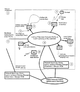
illustrated in Fig. 1, fixed network access points (12) with high data
transmission
capability represent points at which we can install cellular access points or
CAP (10)
(whether large or small, as explained below) in a new wireless networlc based
on the
network architecture (14) of the present invention. These CAP's (10) are much
more
numerous than the number of base stations in a traditional cellular networlc.
Also their
locations do not necessarily follow a pattern that is optimum in terms of
coverage
such as the ideal hexagonal cellular pattern of a cellular networlc. As a
result it is
imperative that the air interface should be designed so as to allow for the
automatic
installation of the CAP's (10), in a manner that is lcnown, and as fiirther
particularized
below.
As sliown in Fig. 1, the networlc (14) consists of a set of terminals (16),
fixed network
access points (12), CAP's (small or large) (10), and a wide-area network (18)
tliat
connects the fixed networlc access points (12) to a network
spectrum/power/antenna-
pointing manager or Controller (20). We refer to all the CAP's connected to a
single
Controller as a network control domain (NCD). The izetworlc control domain
operates
CA 02568899 2006-12-04
WO 2005/120101 PCT/CA2005/000868
-13-
over a geographical local region. Different network control doniains can be
inter-
connected by a backbone networlc (22).
The present invention provides a method for deploying a cellular wireless
communication. network witll the autonomous wireless infi=astructure described
herein. A modified cellular wireless communication network, as well as a
system and
related computer program for defining a networlc controller for managing the
autonomous wireless infrastructure described, is also provided. It is
important to
understand that in this disclosure by "cellular wireless communication
network" the
broader communication network is meant, which includes not only the portable
devices, and the base stations that define the cellular zones by operation of
the
network controller, but also the broader wired/wireless networlc that is used
for
interconnecting base stations, including fixed elements and/or point-to-point
wireless
linlcs.
One aspect of the present invention is that the cellular access points (10)
are installed
by the customer in an autonomous manner. The CAP's (10) of the present
invention
are designed (as particularized below, and otherwise in a manner that is known
to
those skilled in the art) to be low-cost communication infrastructure devices
having a
cost that is preferably similar to that of IEEE 802.11b WLAN access poiizts.
The
customer could go to a local telephone store, such as those operated by the
network
operator and purchase a CAP that is a small access point (10) that is based on
the
modified 3G technology of the present invention rather than one based on the
IEEE
802.11b standard. These CAP's (10) connect to the baclcbone networlc (22) via
a local
area network, or through a wide-area network using for example DSL, or cable
access.
The present invention, in one of its embodiments, contemplates the use of a
physical.
layer employing a modulation scheme that has the properties of spread spectrum
and
is robust to interference. With these properties the radio spectrum can be
reused in
every-cell in the system just like the CDMA systems based on IS-95 or the 3G
standard (CDMA2000 or WCDMA). This type of modulation also allows for
CA 02568899 2006-12-04
WO 2005/120101 PCT/CA2005/000868
-14-
universal frequency re-use by each cellular access point - a requirement that
is
necessary due to the autonon-ious growth of the infrastructure nodes (small
cellular
access points or large cellular access points, (10)).
Communication between the terminals (16) and the cellular access points (10)
utilizes
for example an FDD (Frequency Division Duplexing) air interface, with the
possibility of a future unbalanced spectrum allocation (forward/reverse link),
and the
possibility of a time division duplex (TDD), also included in the autonomous
cellular
networlc.
One of the aspects of the invention is the autonomous growth of the network
architecture described, that it is possible with automatic configuration of
the cellular
access points (10), and a modulation scheme tliat has the properties of
universal
frequency re-use. This means that the fi-equency re-use cluster size is equal
to 1.
CDMA techniques are the prime candidates for modulation. However, current and
future modulation schemes, specifically optimized for this networlc
architecture, are
possible. In particular GSM networks with dynamic selection of the frequency
hopping channel set and hopping algorithm is also possible and an important
niodulation given the degree of deployment of GSM networlcs.
Possible air-interfaces that can be used in the communication networlc of the
present
invention include:
= IS-95 based CDMA systems (backwards compatibility with installed
CDMA base stations - but not optimized to reduce interference).
= IS-95 based CDMA systems with the incorporation of a sleep mode,
i.e. small modifications to IS-95.
= GSM with dynamic selection of frequency hopping set and frequency
liopping sequence.
= WCDMA based systems (with and without sleep mode).
= CDMA2000 IX or 3X system (with and without sleep mode).
CA 02568899 2006-12-04
WO 2005/120101 PCT/CA2005/000868
-15-
= EDGE air interface and other evolutioned of GSM to high data rate
transmission.
= Other Wideband based CDMA system.
= 1X EV/DO system.
= A new air interface based on the use of MIMO with spread space
communication, e.g. spread space-spectrum multiple access (SSSMA)
recently developed at University of Toronto.
= An interface that is based on multi-carrier CDMA.
= All of these interfaces assume the capability for the transmission of a
pilot signal with a code that identifies the access point to the
Controller. This fiinction is required for the automatic configuration of
the cellular access points (10).
While the cellular access points (10) will generally consist of the low cost
micro base
stations described above, in accordance with one particular aspect of the
present
invention it should be understood that based on network infrastructure
considerations
explained below, it may be desirable at specific geographic points that a
cellular
access point (10) actually consist of network infrastructure and related
components
similar to those included in a base station in the current network. Cellular
access
point (10) in this disclosure refers to both base station types, small and
large cellular
access points.
Another feature of the proposed architecture is the automatic configuration of
the
cellular access points (10) upon installation. In order to support this
filnction these
cellular access points are given the capability to perform certain fiinctions
(in a
particular embodiment), in a manner that is lalown:
= The cellular access point (10), in the case of a CDMA air interface, can
be configured with a given pilot transmission power. The allowable
range of transmitter powers will determine the cost of the access point
CA 02568899 2006-12-04
WO 2005/120101 PCT/CA2005/000868
- 16-
and ultimately its deployment strategy. Very low power access points
will be inexpensive and can be purchased and installed by the customer
- autonomous installation and organic network growth. High power
cellular access points (24), or large cellular access points, require
coordinated installation by an RF specialist, subject to health
regulatory requirements, and general RF interference considerations,
and other lcnown requirements.
= State: the cellular access point (10) is "ON" or "OFF" in the sense that
a pilot channel or broadcast channel is or is not being transmitted. It is
always "ON" for large cellular access points (24). For small cellular
access points (26) in accordance with this invention, it may be in sleep
mode if there is no traffic.
= A cellular access point (10) reports its antenna configuration to the
Controller (20). This applies to the case where the cellular access point
(10) utilizes an antenna array (which may consist of as few as two
elements). Configuration generally depends on the concept of antenna
beam angle pointing. In a n-iicro-cellular environment the notion of a
beam is not clear due to the rich multi-path propagation environment,
i.e. we can not form ideal cell sectors. However, a multi-antenna
element signal processing algorithm will still be utilized. This
algorithm will yield a set of antenna configurations that can be selected
by the Controller.
= The cellular access point (10) reports its transmitter power to the
Controller (20), and will receive commands from the Controller to set
the transmitter power.
= The cellular access point (10) may (optionally) report its GPS (Global
Positioning System) coordinates to the Controller (20), if it has GPS,
capability.
CA 02568899 2006-12-04
WO 2005/120101 PCT/CA2005/000868
-17-
= The cellular access point (10) measures the signal strength on all the
pilots that it hears from neighbouring access points (10) and transmits
them back to the Controller (20). Alternately it may measure, or
demodulate, the broadcast channels of all the neighbouring access
points. A vector of coordinates is transmitted with individual entries
being a pair (base station ID, or pilot ID, or auxiliary pilot ID, pilot
power received).
= The cellular access point (10) may have the capability to transmit a
wake-up message to neighbouring cellular access points (10) in order
to get theriz to transmit a signal so that their pilots can be received and
the Controller (20) can establish an interference matrix between
cellular access points (10). This is a matrix consisting of elements
(I_ij) which denotes the interference received at cellular access point
"j" when cellular access point "i" transmits.
The Controller (20) will function. This type of algorithm can be designed by
those
skilled in the art, such as personnel charged with designing algorithms for
cellular
network resource allocation. The prime example of a cost ftlnction is the
minimum
pilot transmission power for each cellular access point (defined in some
manner for a
set of cellular access points) so that a certain geographical area is covered.
A traditional cellular network generally has a five level architecture
hierarchy
including (i) the mobile terminal, (ii) base stations that coimnunicate
directly with the
terminals, (iii) base station cluster controllers that control a group of base
stations and
control hand-offs between base stations, witli a group of base stations
controlled by a
cluster controller, (iv) mobile switching center (MSC) that coniiects to the
cluster
controllers and interfaces the cellular system to the. public switched
telephone
network, and (v) a backbone network that interconnects MSC's. Without soft
hand-
off, in the case of CDMA, this architecture is basically a tree from the
terminal to
MSC levels and a mesh backbone at level (v). In this case the terminals are
assigned
to specific base stations depending on the coverage from each of the base
stations and
location of the terminals. In the case of soft hand-off the terminal should be
CA 02568899 2006-12-04
WO 2005/120101 PCT/CA2005/000868
-18-
understood as belonging to a multiplicity of base stations simultaneously. A
terminal
that communicates with a given base station is considered a member of that
base
station. Membership of terminals in base stations can be determined by a
cellular
structure. A geographical area is partitioned into a set of cells. The cells
need not be
of the same size, and they also need not be regular geometrical shapes. The
cells will
in general have irregular boundaries depending on the propagation conditions
that
depend on terrairi and man made structures such as hills and buildings.
In a cellular network such as a GSM or CDMA network, a terminal and a base
station
utilize power control. The transmitter power is set to a value that is
sufficient to
achieve a given signal strength, or signal to noise ratio (SNR), at the
receiver.
However in order to carry out the power control fimctions the terminal needs
to Icnow
which cell it belongs to, i.e. if the terminal moves away from the base and
power
control function increases the power transmitted to the terminal from the base
station,
there is a point at which this process ends and a hand-off is executed. Such a
point is
determined by the strength of a broadcast signal that in a sense defines the
size of the
cell, or in effect the cell boundary. In the GSM system this signal is the
broadcast
channel (BC), and in the CDMA system such as IS-95 and CDMA2000, it is the
pilot
and synchronization channels. As a result, the size of a cell in a cellular
system is
defined by the strength of the transmitted broadcast channel, or pilot
channel, or
beacon channel. We refer to any of these channels generically as the beacon
channel
- assuming the CDMA system case. The actual cell region is defined by the
transmitter power of the beacon signal, the propagation environment (hills,
buildings,
and structures), and the characteristics of the transmitting antenna in terms
of the
radiation pattern. In an open environment and with an omni-directional antenna
the
radiation pattern is circular and the radius of the cell is dependent on the
transmitter
power. In a classical cellular system the goal is to assign transmitter signal
powers
(beacon signal power) so that a given service area is covered and the degree
of
coverage overlap (i.e. coverage of a given point from multiple cells) is
minimized.
State of the art cellular systems typically have fixed sectorized antennas,
i.e. in a
given cell there is either an onuli-directional antenna (radiation pattern
over 360
degrees), or directional antennas with 3, 4, or 6 directional antennas, each
covering a
CA 02568899 2006-12-04
WO 2005/120101 PCT/CA2005/000868
- 19-
sector of the cell with nominal angles of 120, 90, or 60 degrees respectively.
The
installation of the base station requires the orientation of the antenna
sectors within
the cell, the selection of transmitter power levels per sector, the possible
antenna
down-tilting, and the selection of cell site parameters, such as (in the case
of CDMA)
pilot sequence offset, and various other operation parameters that typically
are
transmitted in the synchronization channel (Walsh function 32 in the IS-95
CDMA
system). An evolved system would incorporate a switched beam antenna at the
base
station. The antenna would contain a number of possibly overlapping beams
which
could be selected for transmitting to the different terminals.
The autonomous cellular system of the present invention is different from the
current
(existing) cellular system in that each base station has the capability to
sense its
environment. It can measure the strength of various beacon signals from
neighbouring
cells and beacons within cells associated witll different antenna beams. It
can
determine the identities of these cells and beams and transmit them to a
Controller. In
the preferred embodiment the transmission to the Controller would be over an
IP
(Internet Protocol) based networlc. Also in the preferred embodiment, the
Controller
would be controlling a set of base stations that is similar to a set of base
stations
controlled by the cluster controller in a current cellular networlc. The
functions
performed by the base station cluster controller would be augmented to include
automatic configuration in the autonomous cellular system. Base stations
having
these attributes can be designed, manufactured and configured by those skilled
in this
particular art.
The Controller in the autonomous cellular system may be designed with
different
degrees of ftmctional complexity. In the simplest case the Conti-oller would
use an
algorithm to determine the main parameters for the different base stations,
including
transnlission power and antenna beam orientation. The network would be similar
to a
current network but with the autonzatic configuration, and with the
configuration not
changing frequently. At a more sophisticated level the Controller could be
performing
a dynamic network optimization by performing resource allocation for a group
of base
CA 02568899 2006-12-04
WO 2005/120101 PCT/CA2005/000868
......~.. ~__~- -_ -20-
stations. Such an algorithm would be continuously making adjustments to the
various
base station parameters and at the same tinie performing joint sclleduling of
ti-affic.
We consider here an example of such an algorithm. We modify the air interface
of a
3G network so that periodically we dedicate one slot of time in the forward
linic only
for the transmission of the pilot and synchronization signal. All the other
signals
carrying user traffic or paging information are turned off. This period may be
several
seconds and the length of the time slot could be equal to one power control
group
(1.25 ms in CDMA2000, or .666 nis in WCDMA). We refer to this slot as the
interference measuring slot. In a sequence of these slots we introduce another
period
L where in one slot per period (one in L) each base station goes into
listening mode
where it measures the signals from the other base stations. In the remaining
slots the
base station is in transmission mode. The listening slots for the different
base stations
are staggered using a randomization algorithm so that when a base station is
in
listening mode, the probability that all the others are in transmission mode
is high.
With a long enougli -measurement time the spread spectrum signals (pilots)
have
enough processing gain for the listening base station to determine the signal
strengths
of a number of simultaneously transmitting base stations. The measured signals
from
all base stations are tllen sent to the Controller. Based on these signals
received at the
Controller, the Controller will run an algorithm that will result in a
decision to
increase the pilot strengths of some of the base stations and decrease the
pilot
strengths of others. There are many possible algorithms here, but assuming
that all the
base stations have the same transmitter pow.er limit, the algorithm would
attempt to
determine the approximate position of the different base 'stations and then
calculate a
set of transmitter powers that in some way maximizes coverage and minimizes
interference of the pilot signals.
In an alternative mode of operation, in the case of a very low number of
terminals per
base station (the above applies to a higher number of terniinals), the base
stations are
all in sleep mode until there is a wake-up signal transmitted by a terminal.
The wake-
up signal is received by a number of base stations that transmit the signal
identification together with the signal strength received to the Controller.
The
CA 02568899 2006-12-04
WO 2005/120101 PCT/CA2005/000868
-21-
controller then determines the base station that received the maximum signal
and
commands that base station to respond to the terminal and initiate a
connection with
that terminal. Each new user (terminal) attempting to initiate a connection
with a base
station is treated in the same manner. The algorithm being run at the
controller would
generally allocate the terminal to the base station receiving the highest
signal, but
there could be exceptions where the allocation to a base station receiving a
lower
signal strength could result in lowei- inter-cell interference.
The commtuiication networlc architecture of the disclosed autonomous cellular
networlc will in general consist of an irregularly placed set of cellular
access points
quite different from the regular "hexagonal cell" structure that we have been
accustomed to in the current (existing) cellular networlcs. In general there
may be a
mix of large and small cells sharing a common frequency band (one RF carrier
in a
CDMA air interface), or we may decide to group the small cells within one RF
carrier
(one network control domain) and the large cells within another RP carrier. As
stated earlier, some cellular access points (10) preferably have a large
capacity
(large access points) and have a functionality similar to that of current base
stations
and a cost somewhere in the neigbbourhood of tens of thousands of dollars, or
a small
capacity small access points) with costs as low as the cost of a terminal. The
large
access points will be on permanently and transmit pilot signals that identify
a certain
coverage region (a cell). The small access points will operate in a sleep mode
in order
to reduce the "pilot pollution" (pilot interference) that is a feature of IS-
95 and IX
networks, (i.e. cause too mucli interference by pilots transmitted from access
points
that are not handling any traffic).
Small cellular access points will be listening to the reverse link cliannel on
a common
access code pattern. Terminals (16) wishing to communicate will initially
transmit a
probing signal to try and wake up sleeping access points (10) (e.g. "hello! I
need
service. Is anyone here?"). After the probing signal is transmitted, the
cellular access
point (10) awalces and starts transmitting a pilot signal. The tern'inal (16)
then
accesses the system through this pilot just like in a 3G cellular network. In
some cases
CA 02568899 2006-12-04
WO 2005/120101 PCT/CA2005/000868
-22-
more than one cellular access point will be awaken and the terminal (16) will
access
the one with the stronger pilot in a manner that is laiown.
The cellular access points (10) are installed in one of two manners:
1. By a networl< operator using a similar methodology to that currently used
to
install base stations .(28). This involves coverage considerations, leasing
arrangements, RF radiation considerations with respect to biomedical issues,
etc.
2. By a customer in an autonomous manner. This may be as a result of lack of
capacity in a certain area or the cost to use another access point (10). This
is driven by
the user in response to specific needs and the installation process is similar
to that of
an access'point for a cLui-ent WiFi network.
If installation of the cellular access point (10) is by the public networlc
operator, then
the power of the transmitter (nominal value, size of cell) can be set by
standard
cellular planning, followed by possible fine tuning from the Controller, in a
manner
that is luiown. If installation of the cellular access point (10) is by the
customer then
the Controller configures the transinitter power taking into account all the
parameters
reported by the access point (10) back to the Controller (20). This occurs by
operation
of the access point (10) infrastructure in cooperation with software control
n.uining on
the Controller for a specific network control domain, in a manner that is
known.
Therefore one of the aspects of the present invention is that it enables
participation of
the customer in the deployment of the communication network infrastructure.
There
are two prineipal deployments. Fiist, a residence where the customer installs
a
cellular access point (10) that is eonnected to a wideband access service such
as DSL
or CATV network. The networlc is controlled by a Controller (20) operated by
the
owner of the spectrum (the service provider), in a manner that is known.
Second, there is a campus or complex that contains a local area network. The
access
points (10) eonnect directly to the ports of the LAN. The home environment is
a
special case of a LAN with a single access point.
CA 02568899 2006-12-04
WO 2005/120101 PCT/CA2005/000868
-23-
In accordance with the invention, the network operator will generally only
manage the
Controller (20) and does not need to invest in the infrastructure deployment -
at least
in heavily built up areas, although it may clioose to do so. The deployment of
the
wireless infrastructure can be done in an autonomous manner by the customer.
The
spectrum used may be owned by the network operator (e.g. standard cellular or
PCS
spectrum), or it may be unlicensed spectrum such as that of the ISM bands, or
it may
be some future block of spectrum such as that currently allocated to TV
broadcasting.
This would result in more spectrum being available to the network operator. In
the
case of ISM bands being used (the free spectrum) a physical layer that is not
based on
FDD must be used. TDD modes available in the 3G standards could be modified
with
the inclusion of sleep modes for such a spectrum allocation (one block).
The Controller (20) also performs network security functions such as
authentication
of the user and the establishment of a call. The user sets up a call, i.e.
logs into the
network, and then goes into an IP transmission mode. The session is encrypted.
The
charges for the wireless access will be based on a combination of charges for
the use
of the wireless access (possibly free for the owner of the cellular access
point (10)), or
possibly combined with a flat-rate service from the network operator. The
cellular
access point (10) could make itself accessible to other users in the network.
The
connection is managed by the network operator. For example., a contract
between the
network operator and owner of the access point (10) is made so that a credit
is given
to the access point owner for carrying third party traffic. Many business
models are
supported by the present invention.
A typical FDD, cellular/PCS system has a number of frequency bands allocated.
For
example, in 'an IS-95 CDMA or CDMA2000 1X, these bands (channels) have a
bandwidth of 1.25 MHz. The Controller manages each of these bands separately,
if
there is a single user in a cell and the access point needs to turn on one of
the CDMA
carriers then it has ai7 option as to which one it will clioose, and this
clioice may
depend on the CDMA cai-riers being used by the neighbouring bases stations. A
minimum system will utilize a single band, e.g. a single IS-95 type of CDMA
carrier.
In the case of multiple CDMA carriers the Controller (20) can allocate traffic
to
CA 02568899 2006-12-04
WO 2005/120101 PCT/CA2005/000868
-24-
different bands (i.e. manage the bands appropriately) so as to increase the
traffic
carried by the network.
By way of example, the present invention can be utilized by a cellular
operator
operating a CDMA network with 1.25 MHz CDMA carriers. A typical North
American system operating on a 5 MHz block of spectrum (i.e. 5 MHz forward
link
and 5 MHz reverse linlc) has the capacity for 3 CDMA carriers, with half a
channel of
guard band on each end of the block.
In the case of 10 MHz blocks the number of carriers is 7. The autonomous
cellular
system of the present invention can allocate a single CDMA carrier for the use
of
small cellular access points (26) and the other CDMA carriers for the use of
large
access points (24). Small cellular access points (26) will be installed by
customers.
Large cellular access points (24) in urban areas will be installed by the
network
operator and in rural areas, where there is little traffic, by customers (e.g.
in farms).
With this installation approach we will avoid having cells with very large
power
(strong pilots) adjacent to cells with weak pilots which may result in
unfavourable
interference conditions.
The present invention therefore can be understood as an autonomous
infrastructure
wireless network, i.e. a wireless network that is deployed using autonomous
installation by customers, whether in whole or in part. This results in
significant
advantages of reduced cost, organic growth and also enabling more efficient
allocation of spectrum. The result will be a network with the capacity to
provide a
much larger set of services than current cellular systems with the same
overall
spectrum allocation.
Preferably the physical layer of the communication network infrastructure of
the
present invention is designed to encompass characteristics that allow the
organic
deployment and growth of the networlc. Such a network consists of base
stations that
can be modeled as black boxes. These base stations have an interface to a
fixed
network on the one side, or a wireless point-to-point link to aiiother base
station, and a
CA 02568899 2006-12-04
WO 2005/120101 PCT/CA2005/000868
-25-
radio interface (or second radio interface) that may configure simultaneous
connections to multiple mobile terminals. We refer to these two interfaces in
the black
box base station (which include the access points (10) described) ag the
baclcbone and
the access interfaces. The backbone interface could be an interface to a wire-
line
network such as an Ethernet, DSL connection, cable modem connection, or a
fixed
wireless point to point connection based on an air interface such as that
provided by
the IEEE 802,.16 standard (WiMAX)
Operation of the present invention is best understood by reference to steps I
through 4
below, where step 1 describes the characteristics of the cellular access point
being
connected. In particular these steps illustrate how the cellular access points
(10) of
the present invention are integrated into the operation of the broader
cellular network
based on the communication network architecture of the present invention. It
should
be understood that steps I througll. 4 below are an example of operation of
the
communication network architecture described in this invention. Other
implementations and therefore other methods of operation are possible. Also,
for
clarity, it should be understood that the references to "cellular access
points" refers to
either a small cellular access point (26) or a large cellular access point
(24)."
1. The cellular access point is designed to support a particular air interface
using
the autonomous infrastructure wireless network auto-configuration protocol.
This air
interface will provide connectivity to any of the terminals that wish to
connect to this
particular cellular access point. Examples of these air interfaces are
modified CDMA
air interfaces obtained from evolutions of IS-95, CDMA2000, and WCDMA systems,
and also evoltltions of non-spread spectrum systems such as GSM.
2. Upon connecting the cellular access point (10) to the backbone network
through the fixed networlc access point (12) a connection of the cellular
access point
to the Controller (20) is established. This Controller (20) has the task of
configuring
all the cellular access points (10) within a given network control domain. The
Controller (20) will probe the cellular access point for a set of
configuration
parameters. These parameters specify the capability of the cellular access
point and
include the following: set of air interface parameters supported by the base
station
CA 02568899 2006-12-04
WO 2005/120101 PCT/CA2005/000868
-26-
such as CDMA type and version number, set of frequency channels supported
(i.e. set
of CDMA carrier frequencies), transmitter power level, aggregate data rate
supported,
antenna pointing configuration parameters, set of transmitting and receiving
frequencies for the transmission of traffic, and the set of frequencies for
transmitting
probing signals, and the frequency for transmitting the beacon signal. In a
typical
frequency division duplex (FDD) networlc there are two blocks of spectrum used
by
the system. We refer to these as the high bloclc and the low block. The high
frequency block is used for the base station to transmit (mobile terminal
receive) and
the low frequency block is used for the tern7inal to transmit (base station
receive).
However in order to earry out a configuration procedure it is preferred that
the base
station also have the capability to receive signals in the high block, i.e.
the base
station should have the capability to receive signals transmitted by otller
base stations.
The base station may also have a Global Positioning System (GPS) receiver, or
an
equivalent system to determine its geographical coordinates. All of these
parameters
should be sent to the Controller (20).
3. Having learned the capability of the base station, the Controller (20) will
then
send a command to the base station requesting it to do an analysis of its
radio
environment. This analysis consists in scanning a given set of frequency bands
and
reporting the results to the Controller (20). For example in a CDMA system the
base
station would scan all the so-called CDMA carriers and report the information
received in the discovered pilot signals to the Controller (20). This
information would
consists of pilot signal strengtli and pilot PN code offset, or pilot ID, or
auxiliary pilot
ID, or cell ID, or sector ID, (where ID refers to an identification mimber)
and the
system information associated with such a pilot signal in a CDMA system. In
other
systems the report would consist of a set of signal strengths and base station
identification parameters. With this informatioii from all the base stations
(and
possibly also the geographical coordinates) the Controller has enough
information to
determine an approximate networlc graph with a set of active base stations and
the
signal strengths received at each base station from a set of neighbouring base
stations.
For example, a large number of base stations being monitored at a given base
station
indicates that in general some of the pilot signal powers of the terminals
could be
CA 02568899 2006-12-04
WO 2005/120101 PCT/CA2005/000868
-27-
reduced - thus reducing what is sometimes referred to in a CDMA network as
pilot
pollution (pilot interference).
4. After the cellular access point reports its parameters to the Controller
(20) and
the Controller learns as much as possible about the radio environment in the
vicinity
of the cellular access point, the Controller (20) will command the cellular
access point
to enter one of a number of possible operating modes in order to be a
potential
provider of connectivity services to mobile terminals that may venture into
the
vicinity of the given base station. Three of the possible modes are i)
continuous
transmission of a beacon signal such as a pilot signal in the IS-95 CDMA
system, ii)
pulsed transmission of a beacon signal ... i.e. the transmission of a signal
with a given
duty cycle, olr bursty pilot, iii) the occasional' transmission of a pilot
signal with the
purpose to pass signal strength information to neighbouring base stations, iv)
a
sleeping pilot signal mode where the base station is in active mode and is
monitoring
a universal access channel that is la-iown to all the mobile terminals, and v)
the
inactive mode where the Controller (20) decides that the cellular access point
is not
required for the foreseeable fttture or the Controller (20) decides that the
cellular
access point has some malfunction. Other modes with similar features are
possible.
In the case of a CDMA system, the continuous beacon mode consists of the
transmission of a pilot signal together with a synchronization signal (Walsh
fiinction
zero and Walsh function 32 in the IS-95 system), The synchronization signal
should
contain information that the terminal (16) can use to access the given
cellular access
point - i.e. from the synchronization signal the terminal finds out the access
channel
that the cellular access point is monitoring. In the case of an IS-95 CDMA
system this
access channel is a PN code mask for the reverse link. Other parameters such
as the
identity of paging channels are also contained in the synchronization signal.
Mode (ii)
is similar to mode (i) but anticipates that future CDMA-like cellular systems
may
contain non-continuous pilots. Mode (iii) is meant to make it possible for
cellular
access points that are essentially in sleep mode to transmit signals to
announce their
presence to neighbouring cellular access points so that a network interference
graph
can be built by the Controller (20). Mode (iv) is required for a system that
has a large
CA 02568899 2006-12-04
WO 2005/120101 PCT/CA2005/000868
-28-
number of small access points (26) that for the most part are not providing
connectivity service to any of the terminals (16). In mode (iv) operation the
cellular
access points can wake up by receiving a wake-up signal in a manner that is
icnown
from a mobile terminal (16). In a CDMA system like IS-95 the standard needs to
be
modified so that during the call set-up phase if a mobile terminal (16) does
not find
any pilot signal then it starts transmitting the wake-up signal. The terminal
(16)
transmits the wake-up signal without having achieved CDMA network
synchronization. Hence the wake-up signal should be a short PN code that
repeats
continuously for a given period of time that is greater than the channel
monitoring
period of a base station that has a sleeping pilot. A base station with a
sleeping pilot
wakes up for a short period of time periodically in order to monitor the
possible
presence of a wake-up signal being transmitted. The concept of sleep mode is
well
laiown in electronic devices that operate on batteries and in other devices
where
energy saving is crucial. In the present invention, however, the sleep mode
has the
purpose of decreasing interference in the network and not the saving of
battery
energy. A classical cellular network typically has a channel that announces to
the
environment the presence of the base station. The continuous transmission of
this
channel (pilot in CDMA) is not desirable in a small cellular access point (26)
that for
the most part may not have any active comniunication with terminals, i.e. is
not being
used by any terminal due to the very low density of terminals.
One advantage of the present invention over existing cellular networks is that
it puts
the control of infrastructure deployment partly in the hands of the customer.
This
could have the effect of stimulating the deployment of wireless services. It
will turn
the infrastructure market into a market that is similar to the personal
computer market.
Growth and usage of wireless services will be more organic. Users will
automatically,
deploy infrastructure to satisfy their needs in hot-spot locations. At the
same time the
service provider (cellular operating company) will make sure that there is
complete
wide-area coverage. Customers will do their own analysis of the cost. On the
other
hand, the fixed network operator will be provided with more traffic and more
revenue.
This is because, regardless of the rate schemes for the usage of customer
deployed
small cellular access points, there will be more traffic on the operator
deployed large
CA 02568899 2006-12-04
WO 2005/120101 PCT/CA2005/000868
-29-
cellular access points part of the network. In this case the overall effect of
this
architecture on the business of a cellular operator would be positive. The
cellular
network operator will also insure that the network is secure by possible
providing
security through a security server
In a key embodiment of the present invention the network described herein is
deployed by a(fxed) network operator. If a small number of cellular access
points
(10) are deployed by the customer and connected to the fixed network operator,
ultimately the traffic on the autonomous cellular network is controlled by the
fixed
network operator. In one particular aspect of the present invention, a typical
DSL link
from a PSTN to a customer is actually operating under the control of the fixed
network (i.e. PSTN) operator, where a portion of the traffic is DSL customer
traffic
(as in the current use) and the other portion of the traffic is wireless
traffic generated
by third party customers.
Security Function
The Controller (20) will set up a secured access session between the terminal
(16) and
the cellular access point (10) in a manner that is Icnown. This includes
encryption and
authentication. The Controller (20) will also determine if unauthorized
transmitters
are using the spectrum. One way to determine if this has happened is when the
cellular access point reports pilots to the Controller that are unlcnown to
the network.
Where the network operator owns the spectrtun, the distribution of cellular
access
points (10) to the customers is controlled by tlie network operator. These
celiular
access points (10) will have identities. These identities will be transmitted
in the pilot.
The identities are reported to the Controller (20) by the access point (10) so
that the
Controller can determine if the cellular access points (10) are authorized to
use the
given spectrum.
Communications Store of the Future
Telephone stores are typically operated by public operating companies as a
method to
distribute eduipment to the end users. Currently these stores generally
distribute only
CA 02568899 2006-12-04
WO 2005/120101 PCT/CA2005/000868
-30-
terminal equipment, e.g. mobile and fixed terminal equipment such as mobile
phones,
pagers, satellite receivers, etc. The communications store of the future, in
accordance
with the present invention, will carry, in addition to terminal equipment,
also network
infrastructure equipment, and specifically cellular access points (10) with
various
capabilities for transmitter power and bit rate capacity. For a modified 3G 1X
system
this would include the power rating, the maximum aggregate data rate, the set
of RF
CDMA carriers supported, and generally frequency band capability.
It should be understood, that in accordance with one aspect of the invention,
the
networlc operator could decide to ask a particular customer to install a
cellular access
point (10) having capabilities in excess of those of the small cellular access
point,
based on particular network requirements in a particular geographic location,
or other
factors. The telephone store could be used to distribute cellular access point
(10)
equipment to customers having these enhanced capabilities.
A telephone store of the future would look like the following:
= Terminal Equipment (telephones/pda terminals, pagers, satellite terminals)
o all the different models with different capabilities for display and
memory
o possible multiple mode terminals (AMPS/IS-95/CDMA2000/GSM
1X-EVDO/Auto Cell, or autonomous cellular capability)
= Cellular access points (let us measure the power rating relative to that of
a
terminal)
o frequency band capability. Specification by frequency band.
o different models: power rating, antenna configuration capability, of a
current mobile terminal
- 0 dB section: same power rating as a terminal, mostly for home
application, single RF carrier.
CA 02568899 2006-12-04
WO 2005/120101 PCT/CA2005/000868
-31-
- 10 dB section: upper limit of customer installed, small business
- 50 dB section: multiple RF carriers, installed by an RF
specialist, mostly network operator installed.
Network Operation Mode/Spectrum Regulation
Currently there are two main types of spectrum allocation/regulation: 1)
Licensed for
a carrier, e.g. cellular/PCS system, and 2) unlicensed, e.g. ISM-band/NII. We
also
currently generally have two types of network operation: 1) public, with the
operating
company installing the infrastructure and 2) private, where the installation
of the
infrastructure is privately done in a home or enterprise. Thc proposed new
system
architecture operates in a number of scenarios as shown in the following
Tables.
Wireless Network Operation Modes/Business Models
Spectrum Public Private Network Public Traffic on
Regulation Network Locally Private
Network
Licensed Current cellular Current system in restricted Leasing of spectrum
Band system access mode (e.g. spectrum
used for testing)
Unlicensed Public WiFi CuiTent main us0 of WiFi Current piggy-backing
Band networks - hot- (e.g. homes, enteiprises) of public traffic on
spots (e.g. private WiFi, e.g. WiFi
airports) without security
enabled.
Wireless Network Technology Choice
Spectrum Physical Layer Switciiing Mode Proposed Wireless
Regulation Standard Network Concept
Licensed Cellular technology, Circuit switching Single Autonomous
circuit switching IG, (origin in telephone Cellular: Hybrid of ad-
CA 02568899 2006-12-04
WO 2005/120101 PCT/CA2005/000868
-32-
Wireless Network Technology Choice
Band 2G 3G => CDMA network) hoc deployed CAP's +
planned deployment of
CAP's using dedicated
spectrum.
Unlicensed IEEE 802.11, various Packet switching Possibly multiple
Band modes, various bit (origin in cornputer autonomous cellular
rates (2.4 GHx, 5 networks) networks sharing
GHz) common spectrum. Use
of cooperative game
tlieory principles in the
controller
Compatibility with Current Cellular Systems
Physical Layer: The physical layer for the communication network architecture
described Ilerein is preferably based on some form of interference resistant
modulation scheme. CDMA systems (e.g. CDMA2000) can be adapted to the
proposed networking concept - e.g. addition of sleep modes for small cellular
access
points (10). The GSM system is less flexible for evolving to the autonomous
cellular
network described, however, adaptation is possible in a manner that is known.
This
would be achieved through the use of dynamic channel allocation in the
cellular
access points under the control of the Controller. The difficulty is in the
minimization
of interference given the highly irregular cell structure of the organically
deployed
network. However, not withstanding spectral efficiency it is possible to
devise a
dynamic channel allocation algorithm if there is a sufficiently large block of
spectrum
available to the system - i.e. if the nuinber of 200 KHz channels available to
the
system is sufficiently large. A modulation scheme with universal frequency re-
use,
and no need for frequency planning, is the preferred choice. A modification of
CDMA2000 1X air interface, or a modification of the European ETSI WCDMA
standard is the prime exaniple of such a desirable modulation format.
CA 02568899 2006-12-04
WO 2005/120101 PCT/CA2005/000868
-33-
Evolution of Cellular Systems
Numerous research groups are working on next generation cellular technologies
throughout the world. However, there is currently no common set of goals or
criteria
to determine the objectives for such a network. In some cases researchers
mention
much higher data rates (10's of Mbits/s), different modulatioii formats (e.g.
OFDM),
unbalanced allocation of spectrum, and place a great emphasis on different
services.
The different generations of cellular systems can be summarized as follows:
= IG -Analog, 800 MHz band (in North America), FM modulation,
somewhat regular cell deployment
= 2G - digital, primarily voice, single data rate service, low rate data,
compatibility with analog (North America), roaming incentive
(Europe), somewhat regular cell deployment
= 3G - variable data rate services, higher peak data rates (2 Mbps and
higher), somewhat regular cell deployment.
= 4G proposed here - autonomous deployment, sleeper base stations,
sleeping pilot signals, the cellular network grows organically, highly
irregular cell deployment, "smart network architecture", all the
networlc smarts are.contained in one of the network control servers, the
Controller in a given network control domain. The physical layer ph.ig-
and-auto-optimize base station.
Modes of Deployment
The proposed autonomous cellular network offers new possibilities for
deployment of
the base stations. In order for the infrastructure deployment to be responsive
to
coverage needs, or to the emergence of new llot spots, it is beneficial to
allow the
deployment to be performed by different individuals or enterprises in an
organic
manner. Base station equipment can be deployed'using the same model as the
deployment of terminals, where different base stations are privately owned.
With the
above model of private, non-operating company, -ownership of the cellular
access
CA 02568899 2006-12-04
WO 2005/120101 PCT/CA2005/000868
-34-
points, or at least the small cellular access points, there is still the need
for an operator
to operate the Controller (20) if high spectral efficiency is required, and
also to
operate the large base stations (24) that will provide coverage over non-hot
spot areas,
or the remaining areas that are not covered by the organic deployment of small
cellular access points. The operating company will also manage the spectrum
that it
currently licenses. This management is preferably realized through the
operation of an
algorithm that optimizes the power levels of the different cellular access
points that
connect to a single Controller (20). The operating company also provides many
access
services such as the secure login to the network in a mobile environment. This
may be
achieved with a point to point encryption of the transmission on the wireless
link or
an of end-end tunnelling protocol operating between the mobile terminal and a
network security server as is the case in a virtual private networlc.
The traffic carried by small cellular access points can be that of the small
cellular
access point owner or third party traffic, where in one particular aspect of
the present
invention the installer of the base station (large or small) is credited by
the operator
of the baclcbone networlc for carrying such third party traffic. The cellular
access point
would have a configuration parameter that would determine the degree to whicli
it is
willing to carry third party traffic.
From the standpoint of a terminal (16) and the billing for network access
three main
modes of operation are contemplated (but others are possible). In mode I the
terminal
(16) accesses a large base station (12) installed by the cellular operating
conlpany in a
manner that is similar to that in the current cellular system - we refer to it
as the wide-
area mode. This type of connectivity is the default mode and exists anywhere
that
there is coverage by a cellular company. This coverage is only limited by the
coverage that can be provided by the cellular company. In most countries in
Europe
this coverage would practically include the whole country with a small
percentage'of
the total area of the country being the exception. In mode II the terminal
(16) belongs
to the owner of a small cellular access point (26). The prime example here is
that in a
home where a small cellular access point (26) is installed to offer wireless
voice and
data services in a manner where the operation is seamless with the wide area
networlc
CA 02568899 2006-12-04
WO 2005/120101 PCT/CA2005/000868
-35-
(mode I). In this mode we would expect that air time is free but that the
mobile user is
a subscriber to the operator of the baclcbone network and is using its
services. In this
mode the small cellular access point would be similar to a current WiFi access
point
that is installed in the home, but with the added benefit that the small
cellulai- access
point (26) would handle both voice and data traffic and that the terminal (16)
would
be the same terminal with the same air interface for the whole cellular
network. We
may also refer to mode II as the home hot-spot mode. Mode III of operation
involves
the terminal in a non-home hot-spot area. We may also refer to it as the
roaming hot-
spot mode. In this mode the behaviour of the terminal (16) in terms of
handoffs,
power levels, and bit rate capability (we expect higher bit rates in smaller
cells) is
similar to that of mode II but the billing may be different because the user
is not the
owner of the cellular access point.
The present invention therefore meets the objectives of 3G but in a manner
that
permits use of existing infrastructure to provide the advantages of what is
(in 3G)
proposed as a new infrastructtue.
In terms of the air interface, the present invention provides a communication
system,
a communication network infrastructure and a method of deploying a
communication
network that maximizes the capacity per cell per MHz, handles inter-cell
interference,
and easily accommodates hand-offs. The technologies devised for the physical
layer
of 3G systems and their continuing evolutions to higher bit rates provide the
base for
the physical layer of the invention described, modified to handle large
degrees of cell
non-regularity and a large nLunber of small cellular. access points (26) that
will in
many cases be lightly loaded in terms of the number of users.
Autonomous Infrastructure GSM with Frequency Hopping
The GSM cellular standard is based on GMSK modulation (a generalized form of
QPSK) and slow-frequency hopping. This modulation scheme does not have the
interference robustness characteristics of spread spectrum, or CDMA, and
contrary to
CDMA requires a frequency re-use cluster size that is generally greater than
unity.
CA 02568899 2006-12-04
WO 2005/120101 PCT/CA2005/000868
-36-
However, the frequency hopping option does offer some robustness against
interference that is generally referred to as interferer diversity. Frequency
planning in
a GSM network starts with the partion of a block of spectrum (e.g. 5 MHz, or
10
MHz) into a set of 200 KHz channels. These channels are then partitioned into
sets
and allocated to cells and sectors. A set allocated to a specific cell is
lalown as that
cell's cell allocatiofa (CA). For example with 120 degree sectored antennas, a
re-use
pattern of 3/9 means a re-use pattern of 3 cells or 9 sectors. For each set of
channels in
a sector we then create a set of frequency hopping patterns. If there are N
channels
(200 KHz) then we can create N orthogonal frequency hopping patterns. In
legacy
GSM networks the frequency re-use cell clusters are typically arranged in a
regular
pattern and the cells generally have a constant size. However with the
disclosed
concept of autonomous deployment the access points or base stations will be
deployed
randomly throughout a service area and the cell sizes may have large
variations. The
selection of the frequency assignment channels at each sector would require
the base
station to monitor its environment, i.e. monitor all the available RF
channels, and
transmit these to the Controller. The Controller would then select a subset of
these
channels, a CA, to determine a frequency assignment for that particular
cell/sector.
The Controller would then send a set of configuration parameters to the base
station to
configure it as a typical base station from the standpoint of terminals that
would move
into its cell. These parameters would include the following:
= the set of radio frequency channels used in the cell (CA), together with the
identification of the broadcast channel (BCCH) carrier.
= the TDMA frame number (FN)
The base station would then be commanded to go into either sleeping mode or
beacon
(broadcast channel) transmission mode. In
With that frequency assignment selected a frequency hopping sequence would be
generated and sent to the base station by the Controller.
The following summarizes the operation of a GSM based autonomous
infrastructure
cellular system in accordance with the present invention:
CA 02568899 2006-12-04
WO 2005/120101 PCT/CA2005/000868
-37-
=
The base station (as described above) has the capability to receive signals on
the low-band. This is the normal reception band (terminals transmit in the low
frequency band in an FDD system).
= The base station will have the added capability to receive signals on the
high
band. This capability is used to monitor transmissions from neighbouring base
stations.
= The base station reports a frequency block containing channels in the high
band and low band that it has capability to monitor (i.e. RF band capability)
to
the Controller.
= The Controller will take a subset of these bands that it is interested in,
i.e. for
which it is running a configuration algorithm, and command the base station to
monitor these bands and provide interference (or received signal) information.
= The base station scans all these bands and sends the information to the
Controller. Stay in one frequency for a hopping cycle, then move to another
frequency. Report the measurements in terms of signal powers.
= The Controller will use the channel measurements to decide on a hopping
sequence for the newly installed access point.
= For full duplex operation the down link transmission frequencies (in a
hopping
pattern) are offset from the uplink transmission frequencies by a constant
separation. Hence the determination of the downlink hopping pattern
automatically determines the uplink hopping pattern for the same link.
= Sleeping broadcast channel: With many GSM small access points it is
important not to have the broadcast and synch channels "ON" continuously as
in the case of a legacy GSM system, as this would cause unnedessary
interference from small access points that have zero load (no users). The
modified system introduces a mechanism where the mobile terminal, after
sensing the channel and not finding a system, transmits an access point
awakening signal. This signal is transmitted on a well lazown system channel
CA 02568899 2006-12-04
WO 2005/120101 PCT/CA2005/000868
-38-
or channels. We refer to this signal as being transmitted in an ALARM
channel. A particular system may operate with more than one ALARM
channels. If more than one such channels exists then the mobile terminal can
perform a transmit cycle through all of the ALARiV1 channels in order to wake
up the terminals.
Network Architecture
The autonomous infrastructure wireless network disclosed here requires an
access
type of network where base stations, or access points, can readily be
attached, or
plugged in, using a paradigm similar to the attachment of an electrical
appliance to the
power grid. Also, in keeping with the trend in communication networks, this
network
should be an IP (Internet Protocol) based type of networlc. There is a
multiplicity of
network architectures that may be utilized for this purpose. In the following
we
discuss some of these possibilities.
(a) Ethernet LAN
The prime example of an IP based base station interconnection network is a
hard-wired Ethernet LAN. The base stations would contain an interface that
connects directly to the LAN, or they could connect using a network interface
card as an added module. Each base station would automatically configure an
IP address for the LAN and at the same time initiate communication with the
Controller. The plugging in of the base station would result in two phases of
auto-configuration. In the first phase there would be a configuration for
communication in the interconnection network including the auto-configuring
of an IP address and the acquisition of the IP address for the autoilomous
networlc Controller. With such communication established, the base station
will begin the second phase of configuration - the configuration of the
autonomous cellular air interface, or wireless access, parameters. The means
of connecting the cellular access point (CAP) to the network is depicted in
Figure 2 a). This figure does not show the Controller which is a node in the
network that is included in the block labelled as "Intei-net".
CA 02568899 2006-12-04
WO 2005/120101 PCT/CA2005/000868
-39-
b) Public switched telephone network
The second example is that of a public switched telephone networlc (PSTN).
The simplest example here is that of a DSL (digital subscriber line)
connection
to a home or small business. This DSL line can be one of a number of
evolving DSL technologies, e.g. ADSL, VDSL, xDSL, or other. With this
option we can easily create wireless home networlcs, or small inteiprise
networks that are compatible at the wireless physical layer with regular
cellular networlcs (compatibility aspect of autonomous cellular). These
networks will have an advantage over existing WiFi networks in terms of
security and interference management in areas with a high density of wireless
devices. With this type of networlc the base station may be customer owned or
owned by the operating company - i.e, the company that operates the
autonomous network Controller. The method of connection of the CAP to the
network is shown in Figure 2b).
Anotlier altei-native to this type of network is a networlc where the base
station
(CAP) is placed closed to a home but serves a multiplicity of homes. The
connection method is shown in Fig. 2c). The base station would likely be
connected over fibre to a switch or router in the PSTN. The number of homes
served by one base station (CAP) would depend on the capacity required at
each home and the amotint of radio spectrum available. For example, if we
intend to provide services such as IP-TV to the home then a large capacity per
home is required and each base station will have to be located at such a
distance from the home that it serves a small number of homes depending on
the over-all bandwidth available. This alternative is attractive in comparison
to
state of the art proposals for IP-TV involving hardwired connections to the
home, in that it provides for the portability of terminals in a home
environment
and at the same tinie reduces the wiring costs - i.e. the costs of running
wire to
each home.
c) Community Access Television Networlc (CATV)
CA 02568899 2006-12-04
WO 2005/120101 PCT/CA2005/000868
-40-
A CATV network is a logical networlc alternative for the interconnection of
base stations. It llas a high capacity and wide coverage (deployment) in
residential areas. As for the PSTN option discussed above there are two
possibilities here. In the first -case we may install a base station (CAP) in
a
home. This base station would replace an existing cable nlodem (cun-ently
used for Internet access). One interface of the base station would consist of
a
cable modem with the capability to possibly tune into one of a number of
cable channels (6 MHz in North America). The other interface would be the
autonomous wireless interface that provides wireless access within a liome
environment and its vicinity and is compatible with a wide area cellular
network. This method of connection is shown in Fig. 3a).
The second approach would be to have the base station (CAP) placed outside
the home and at a given distance from the home. The exact distance would
depend on the capacity of the wireless interface required. Usilig a large
distance requires greater transmission power and results in a greater number
of
homes served by the base station. The base station could replace an existing
tap-box in the cable disti-ibution network which typically feeds 8 homes, or
it
could be placed further back in the cable distribution plant at a node that
serves several hundred homes. The choice of location on the cable distribution
network depends on the RF spectrum available and the services being
provided to the home - i.e. the ultimate capacity requitement per home. The
greater the capacity requirement the smaller is the cell size and the closer
to
the home is the CAP.
d) Power Line Communications Network (PLC)
Another alter-ilative for the interconnection of base stations would be a
power
line communication (PLC) network or, also referred to as a broadband power
line communication network (BPL). The overall network would consist of a
backbone network (e.g. backbone of telephone network) with nodes being
points of connection to a power line. Each such node would connect to a
branch of the power grid serving a limited area. Then, for each such branch a
CA 02568899 2006-12-04
WO 2005/120101 PCT/CA2005/000868
-41-
multiplicity of base stations (CAPs) could be connected. The method of
connection is shown in Fig. 3b. Each base station would, again, have two
interfaces. One interface consists of a modem for power line communications
using the particular modulation for that system - e.g. some form of OFDM.
The other interface would be the wireless access interface for the autonomous
cellular network. The size of each of the above branches of the power line
grid and the allowed number of connections of base stations to a branch would
depend on the capacity required for each base station and the capacity
provided by the PLC scheme. The traffic handling capacity of all the base
stations in one branch would have to be smaller than the capacity of the PLC
scheme. If the we wish to increase the number of base stations in one branch
in such a manner that the above capacity constraint is violated, then the
solution would be to split the branch into two smaller brances by adding extra
nodes in the baelcbone networlc. This type of network has the advantage that
the wiring is already in place due to its primary fiuiction in power
distribution.
Also, such a network would provide good coverage in in-door environments,
malls, underground levels, etc,
e) Fixed wireless access networlc
The base stations (CAP) may be interconnected by a fixed wireless access
network such as a lnesh networlc based on the IEEE 802.16 air interfaee
(WiMax), or a wireless LAN based on the IEEE802.11 a protocol as shown in
Fig. 3c) Each node in the mesh networlc would be a base station in the
autonomous cellular network. Each base station would have two radio
interfaces. One interface would connect to the mesli networlc. The second
interface would provide wireless access to mobile and poi-table terminals over
the autonomous cellular network. The mesh wireless network should be
designed in such a manner that new nodes (CAP's) are easily deployed so as
to allow for the organic growth of network in the spirit of the autonomous
infrastructure wireless system concept.
CA 02568899 2006-12-04
WO 2005/120101 PCT/CA2005/000868
-42-
Terminal Considerations
In a typical state of the art cellular network (legacy cellular system), base
stations
transmit a signal either continuously or periodically (e.g. one slot per
frame) whose
purpose it is to "announce" the presence of a base station to terminals that
move into
the cell served by such a base station. These signals (channels) may be called
broadcast channel, synchronization channel, beacon channel or signal, pilot
channel
or signal, or other. An essential concept in the disclosed invention is that
of a sleeping
base station.
If a certain cell has no users then we don't want the above signals (channels)
to be
necessarily transmitted because we may have a very high density of base
stations with
no users and this would cause unnecessary interference. The classical example
here is
the pilot signal in a CDMA system, where the resulting interference is
sometimes
called "pilot polution". A base station with the above-referenced signal
turned OFF is
said to be in sleep mode. Now, in a legacy cellular system when a terminal is
powered
ON then it immediately attempts to synchronize to the above mentioned
synchronization signal, pilot signal, or beacon signal. If the base station is
in sleep
mode theii the terminal must have a mechanism to awaken the base station.
Hence a
terminal in an autonomous cellular network should have the enhanced capability
(over
terminals for legacy cellular systems) to transmit a signal that we refer to
here as an
ALARM signal (synonymous with a wake-up alarm). The terminal, upon being
powered up will first search for local cells that are awake, in the normal
operation
mode of siich a terminal in a legacy cellular system, and if no such cell is
found it will
transmit the ALARM signal for a given period of time. Afterwards it again
searches
for the presence of base stations. It will repeat this cycle of transmitting
the ALARM
signal and listening for a certain number of times, at which point, if still
there are no
base stations present, it will assume that it is not within range of an
autonomous
infrastructure wireless network and turn OFF.
Services
The autonomous infrastructure. cellular network of the present invention is
envisioned
as a 4 i generation wireless network. The three main telecommunication
services of
CA 02568899 2006-12-04
WO 2005/120101 PCT/CA2005/000868
- 43 -
today are voice, video distribution, and Internet access. Traditionally these
services
have been provided by three distinct networlc architectures: telephone
network,
CATV networlc, and the Internet. The trend is for all of these architectures
to
converge to a single architecture that provides the three services - the so-
called triple
play. A key requirement for the provision of triple play is sufficient
capacity in the
access network. Another trend in the industry is for the use of wireless in
the access
part of the network. Wireless provides portability and reduces wiring costs. A
third
requirement is the reduction of the cost of installation. The autonomous
infrastructure
wireless network concept disclosed here is an ideal technology to meet these
goals.
The network can be designed to be IP based and to provide voice over IP
service
VoIP, television over IP service (IP-TV), and regular niulti-media Internet
access. In
the case of IP-TV there are different emerging standards depending on the size
of the
terminal or display device. Services with smaller terminals currently being
developed
for cellular transmission can be adopted in the autonomous cellular network in
the
same manner as currently being planned for mobile cellular networks. However,
due
to the possibility for much smaller cells the autonomous cellular system can
also be
used for the distribution of video signals to the home using IP-TV.
Radio Spectrum
There is currently great interest in finding new uses for previously allocated
spectrum
for TV broadcasting. These TV UHF bands below I GHz are rarely used. O,n the
other hand regulatory requirements require that these channels be available if
required
for use by a transmitter according to the old spectrum allocation license. The
solution
being discussed is to design radios that automatically detect if a particular
band is
being used and to vacate the band if it starts being used. The autonomous
infrastructure networlc concept is ideal for this spectrum usage requirement
and is a
candidate architecture for the use in the future allocation.