Note: Descriptions are shown in the official language in which they were submitted.
CA 02569002 2006-12-20
WO 2006/045178 PCT/CA2005/001579
-1-
TITLE: METHOD FOR THE AUTOMATED PRODUCTION Ot= TH REE-
DIMENSIONAL OBJECTS AND TEXTURED SUBSTRATES FROM TWO-
DIMENSIONAL OR THREE-DIMENSIONAL OBJECTS
FIELD OF THE INVENTION
[001] This invention relates to the production of three-dimensional
objects or a substrate having a textured surface (e.g., a relatively thin
sheet
that is treated such as by pressure and/or vacuum molding to provide a
topography or relief pattern therein), utilizing an original object. The
original
object may itself be a three-dimensional object or, alternately, it may be a
non-textured substrate (e.g. a photograph). In one particularly preferred
embodiment, the method relates to producing a reproduction that is larger or
smaller than the original object wherein, in the reproduction, the depth of
the
reproduction in the Z dimension, or the texture of the reproduction, is scaled
from the starting object to a different degree then the length or width of the
starting object in the X and/or Y dimensions.
BACKGROUND OF THE INVENTION
[002] Various different techniques have been developed for the
inexpensive reproduction of original works of art. For example, a mold for use
in vacuum molding may be prepared by applying a liquid silicone rubber
compound to the surface of an original work of art, allowing the rubber
compound to cure to produce a rubber mold. The rubber mold is then
subsequently used to create a metal mold, which is then used to create
reproductions. Such processes have limited acceptability as they may
jeopardize the physical integrity of the original work of art. Accordingly, an
alternate method for reproducing an original work of art comprises using a
person with artistic ability to copy an original work of art thereby creating
an
artwork that may then be used to produce a mold that is utilized in vacuum
molding. Therefore, there is no risk of damage to the original work of art.
See
for example United States Patent Numbers 3,748,202, 3,880,686, 4,001,062,
4,971,743 and 5,958,470. One disadvantage of this approach is that, to avoid
risk of damage to an original artwork, an artist must be employed each time a
CA 02569002 2006-12-20
WO 2006/045178 PCT/CA2005/001579
-2-
different artwork is to be reproduced.' Further, the reproduction is of a copy
and, not the original. Further, an artwork cannot be quickly reproduced
without
risk of damage since time must be provided for the artist to produce the copy.
[003] It is also been known to create embossing dies, which are then
used to create reproductions. See for example United States Patent Number
5,182, 063.
[004] If a mold is produced from a work of art, whether an original or a
copy, a male mold is first produced. The male mold is subsequently used to
make a female mold, which is then used to vacuum form a thermoformable
plastic sheet. The female mold may be prepared by pouring onto the surface
of a male mold a suitable castable material which, when hardened and
released from the male mold, provides a female mold having the reverse
texture present in the male mold. Such castabie material has a tendency to
shrink as it hardens. For example, epoxy resins experience considerable
shrinkage during the curing process. Accordingly, to overcome the problems
associated with the use of castable shrinkable material, the male mold may be
enlarged sufficiently to account for the shrinkage that will occur when the
female mold is made. Accordingly, a picture may be taken of the original,
digitally stored and then printed onto a sheet. The picture image is expanded
from the original size of the picture to an expanded dimensional size wherein
the length and width are expanded to an extent to which the female mold
shrinks from its original poured state to its hardened state. A hardened
compound is brushed onto the printed expanded image to replicate the brush
strokes of the original picture image thereby creating a male mold. The
female mold is then prepared by pouring a castable shrinkable material onto
the male mold and curing the castable shrinkable material. See United States
Patent Number 6,444,148. One disadvantage of this approach is that the
texture in the reproduction is again of a copy an original.
SUMMARY OF THE INVENTION
[005] In accordance with one aspect of the instant invention, there is
provided a method and apparatus for the automated production of
CA 02569002 2006-12-20
WO 2006/045178 PCT/CA2005/001579
-3-
reproductions, which may be textured substrates or three-dimensional objects
comprising acquiring an electronic file of an existing two-dimensional image
(e.g., a non-textured substrate such as a non-textured picture) or of a three-
dimensional object (such as an original oil painting or a car) and preparing
the
reproduction wherein the ratio of the size of the original object (the length
and/or width in the X and Y dimensions) are scaled on one basis and the
texture or depth of the object in the Z dimension is scaled on a different
scale.
[006] A textured substrate is used to refer to a carrier member that
has a topography or relief pattern therein. A substrate is typically an extent
of
material (e.g., a sheet) whose length and width are relatively large compared
to the thickness of the material. An example of a substrate is a sheet of
thermoformable plastic used in vacuum or pressure molding. For example, in
one embodiment, the reproduction may be used as a billboard, poster or the
like, or the reproduction may be of a picture. In such a case, the substrate
is
essentially flat except for the relief pattern that is provided in the
substrate. In
other words, the front or image bearing face of the substrate, except for the
relief pattern provided therein, (i.e., the length and width of the substrate)
extends in a two-dimensional plane. Other examples of such uses include the
use of the substrate as a face for a clock, product packaging, calendars,
flags,
hang tags, panels and the like. It will also be appreciated that the substrate
may be curved or of an alternate configuration. For example, the substrate
itself could be configured to be applied to part or all of the exterior
surface of a
consumer product or distributable such as a pen, a clock body, a mug, a lamp
body, a lamp shade, a vase, a jewelry box, furniture, an article of clothing
(e.g.
a front panel of a t-shirt), a plate, a hat or the like. Therefore, such
consumer
objects may be formed according to traditional rnethods and the substrate
applied to part or all of the exterior surface. of such a consumer product so
as
to provide essentially a decorative facing for such an object.
[007] It will be appreciated that a substrate is a three-dimensional
object as it has a length, width and a depth. However, the substrate may have
an image provided thereon but may not have a topography or a relief pattern.
An example of such a substrate is a photograph. The photographic image is
CA 02569002 2006-12-20
WO 2006/045178 PCT/CA2005/001579
-4-
two-dimensional. Therefore, such a substrate is a non-textured subttrate.
[008] A three-dimensional object is used herein to refer to an item
whose depth is not represented merely by the thickness of the material from
which the item is made. For example, a mug or cup has a depth that.is greater
than the thickness of the material from which the mug is made. In accordance
with another embodiment of this invention, the reproduction may be used as
part or all of a three-dimensional object. Therefore, the reproduction may
form
part or all of a pen, a clock body, a mug, a lamp body, a lamp shade, a vase,
a jewelry box, furniture, an article of clothing (e-g. a front panel of a t-
shirt), a
plate, a hat or the like. For example, if the three-dimensional reproduction
is a
three-dimensional reproduction of a person or a reproduction of an oil
painting, then the substrate that carries the three-dimensional reproduction
could be used to form the cylindrical face of a rnug or, alternately, used as
the
cylindrical body of a mug. Accordingly, a person could acquire a mug bearing
a three-dimensional reproduction of a member of their family or of an original
work of art wherein the image is integrally formed as part of the mug. For
example, in the case of a mug, the mug may be prepared by blow molding,
injection molding, rotational molding or other known manufacturing processes
that use a mold. The topography may be incorporated into the mug so that the
mug, when formed, contains the selected topog raphy.
[009] For example, the original object rnay be an original oil painting
(a textured substrate). The length and width of the reproduction in the X and
Y dimensions may, for example be 1/4 the size of the original. In such a case,
if the dimension of the brush strokes (i.e. the depth of the brush strokes in
the
Z dimension) were also scaled by 1/4, then the topography or relief pattern in
the reproduction would be subtier. According ly, the brush strokes may not
appear to be realistic. One advantage of the instant invention is that by
utilizing a different scale factor for texture (depth) as opposed to the
length
and width of an object, the reproduction may have a texture that is
perceptible
to an observer and is also realistic. For example, if the scale factor used
for
the Z dimension is one, then the brush strokes will have the same topography
as the actual brush strokes in the original oil painting even though the size
of
CA 02569002 2006-12-20
WO 2006/045178 PCT/CA2005/001579
-5-
the oil painting is altered. Therefore, the brush strokes may look realistic,
[0010] The original object may alternately be a photograph (a non-
textured substrate) of, for example, an oil painting or a picture of a person.
However, the subjects of the original photographs do contain texture.
Accordingly, a digital picture may be taken of the object and a computer
program utilized to create a work file, which includes information on the
topography/depth of the subject of the photograph. An example of such an
algorithm is set out in United States Patent Number 6,515,659. Other such
computer programs are known in the art. Accordingly, even if the original
object does not have a textured surface, the reproduction may have a
textured surface that is based upon the subject of the original object.
[0011] The reproduction may be an advertisement, such as a poster,
billboard or the like. In such a case, the advertisement is preferably
expanded
several fold (e.g. from about 2 to about 500 times the length and width of the
original object). If the original object has a textured surface, or if a
topography
is *produced using a computer program, then it may be desirable that the
reproduction have a textured surface but wherein the textured surface of the
reproduction is scaled at a different rate to the scale used in the X and Y
dimensions. For example, in the case of a poster or billboard, it may be
desirable to use a scale factor that is smaller than the scale factor utilized
on
the X and Y dimensions. If the same scale factor is used for the Z dimension,
then the maximum length in the Z dimension may be such that the object
does not appear proportional to an observer, does not fit within a case (for
example if the poster is provided in a glass enclosure) or the substrate may
be dimensionally unstable if it is exposed to the elements (e.g., part of the
reproduction may sag or deform due to gravity or when subject to strong
winds).
[0012] Another example is a textured advertisement that is provided,
for example, in a magazine. In such a case, the original object may be a
standard print advertisement (e.g. a non-textured photograph) provided by a
client. In such a case, as discussed previously, a computer program may be
utilized to provide the Z dimensions for the textured reproduction. However,
CA 02569002 2006-12-20
WO 2006/045178 PCT/CA2005/001579
-6-
in this case, it is preferable that the scale factor that is used for the
length and
width of the subject contained in the original photograph is scaled at a
different scale to the depth of the subject of the original photograph. For
example, the depth of the textured reprod uction in the Z dimension may be
scaled at a substantially reduced scale cornpared to the scaling utilized for
the
X and Y dimensions. In such a case, the advertisement has a bold
appearance and will attract the attention of the user but will be able to be
contained within a printed publication (such as a book, magazine, journal or
the like).
[0013] It will be appreciated that the three-dimensional reproduction
may be monotone. For example, the substrate may merely bear the
topography of the object. Preferably, the reproduction also bears an image of
the original object. The "image" of the original object is the equivalent of a
two-dimensional reproduction of an object such as would be obtained by
printing a picture of the object. The image contains two-dimensional data of
the element or elements forming the object and may be black and white but is
preferably colour. Accordingly, in a preferred embodiment, the three-
dimensional reproduction contains the image of the object (which is obtained
from the scaled X and Y data) and the relief pattern or topography of the
object (which is derived from the scaled Z data). In a particularly preferred
embodiment, the three-dimensional reproduction bears a colour reproduction
of the image of the object.
[0014] The actual production methods that are employed to produce
the three-dimensional reproduction may be any of those named in the art.
The reproduction may be prepared by first printing an image on the substrate
and then treating the substrate (e.g., by molding or by subjecting the surface
to a three-dimensional printing process) to produce a topography. For
example, the scaled XYZ data may be used to prepare a mold and the mold is
subsequently used to prepare the reproduction. Accordingly, the scaled XY
data may be used to print an image, preferably a colour image, on the
substrate and the substrate is subsequently inserted into a mold whereby the
three-dimensional reproduction is prepared. An example of a molding process
CA 02569002 2006-12-20
WO 2006/045178 PCT/CA2005/001579
-7-
is disclosed in United States Patent No. 5,958,470'
[0015] Alternately, for example, an object may be prepared by blow
molding or by rapid prototyping technology (e.g. using a robot to build an
object by joining together typically using heat pieces of plastic, based on
instructions provided by a computer) and a transparencyõbearing a colour
s'
reproduction in two-dimensions of the object 'may be aligned with the
topography on the object and non releasable attached thereto, such as by
laser stereolithography. Alternately, the image may be applied to the object
by injection molding against a painted mold or die.
[0016] Alternately, the scaled XYZ data may be used to directly
produce the reproduction. For example, the scaled XY data may be used to
apply an image, preferably a colour image, to the substrate (e.g. by a
printing
process) and the scaled Z data may be used, to directly create the topography.
For example, the topography comprises a plurality of depths in the Z
dimension. The differing depths in the Z dimension may be formed in the
substrate by applying a variable mechanical force in the Z direction to the
surface of the substrate. The variable mechanical force may be applied for
example, by a dot-matrix printing head, a daisy wheel printing head, a matrix
of pins that are moveable in the Z dimension, an electronic deformable LCD
or any other means known in the art.
[0017] The mold may be prepared by any means known in the art. For
example, the mold may be prepared by machining, laser cutting, CNC
machining, CNC laser cutting, fused deposition modeling, stereo lithography
and/or casting.
[0018] Accordingly, in one embodiment of the instant invention, there is
provided a method for producing a three dimensional reproduction of an
object comprising: -
(a) acquiring electronic data representing a work image of the object,
the work image including a three dimensional representation of the
object, wherein in the representation of the object has a length in each
of the X, and Y dimensions and a plurality of depths in the Z dimension;
CA 02569002 2006-12-20
WO 2006/045178 PCT/CA2005/001579
-8-
(b) processing the electronic data to obtain scaled XYZ data'wherein at
least one of X and Y are scaled by a first scale factor and Z is scaled
by a second scale factor, the second scale factor being different from
the first scale factor; and,
(c) using the scaled XYZ data to prepare the reproduction of the object
on a substrate.
[0019] In one embodiment, step (c) comprises using the scaled XYZ
data to prepare a mold and using the mold to produce the reproduction.
[0020] In another embodiment, step (c) comprises using the scaled
XYZ data to directly produce the reproduction.
[0021] In another embodiment, the processing includes:
(a) processing the electronic data with the first scale factor for
scaling the length of at least one of the X and Y dimensions of
the three dimensional representation of the object to provide a
first scaled dataset; and,
(b) processing the first scaled dataset with. a second scale factor
for scaling the plurality of depths in the Z dimension of the three
dimensional representation of the object to provide a second
scaled dataset;
wherein the reproduction is prepared using the second scaled dataset.
[0022] In another embodiment, step (b) includes:
(a) processing the electronic data with a first scale factor for
scaling the length of at least one of the X and Y dimensions of
the three dimensional representation of the object to provide
scaled XY data; and'
(b) processing the electronic data by applying a rule based on
the first scaling factor, wherein the rule represents the second
scale factor, to obtain the scaled Z data.
[0023] In another embodiment, the length in the X dimension of the
CA 02569002 2006-12-20
WO 2006/045178 PCT/CA2005/001579
-9-
three dimensional representation of the object is varied by the first scale
factor, the plurality of depths in the Z dimension of the three dimensional
representation of the object is varied by the second scale factor and the
length in the Y dimension of the three dimensional representation is varied by
a third scale factor, wherein the third scale factor is from 80 to 120% of the
,.,
first scale factor.
[0024] In another ennbodiment, the method' further comprises selecting
the second scale factor so that the reproductio'n has a realistic appearing
texture.
[0025] In another embodiment, the reproduction has X and Y
dimensions each having a length and a Z dimension with a plurality of depths
and the method further cornprises selecting the second scale factor so that,
when the reproduction is viewed by a person, the, length of the reproduction
in
each of the X, and Y dimensions and the- plurality of depths of the
reproduction in the Z dimension appears to have been scaled by the same
scale factor.
[0026] In another embodiment, the reproduction has a texture and the
method further comprises selecting the second scale factor so that the texture
is perceptible.
[0027] In another embodiment, the reproduction has a visual focal point
and the method further comprises selecting the second scale factor to position
the visual focal point of the reproduction at a selected portion of the
reproduction.
[0028] In another embodiment, the reproduction includes a three
dimensional representation of a consumer product and has a visual focal point
and the method further comprises selecting the second scale factor to position
the visual focal point of the reproduction at the focal point of the consumer
product.
[0029] In another embodiment, the second scale factor is a constant.
[0030] In another embodiment, the second scale factor varies at
different positions in the work image.
CA 02569002 2006-12-20
WO 2006/045178 PCT/CA2005/001579
-10-
[0031] In another embodiment, the object is a person and a' first value
for the second scale factor is used for at least one of the person's lips and
eyebrows and a second value for the second scale factor is used for the
person's nose.
[0032] In another embodiment, the reproduction is larger than the
object and the second scale factor is in the range from 0.9 to 0.1 times the
first scale factor.
[0033] In another embodiment, the reproduction is smaller than the
object and the second scale factor is in the range from 2 to 1,500 times the
first scale factor.
[0034] In another embodiment, the reproduction is smaller than the
object and the second scale factor is in the range from 15 to 200 times the
first scale factor.
[0035] In another embodirnent, the object bears a two-dimensional
image and the method further comprises producing the work image from the
two dimensional image.
[0036] In another embodiment, the object comprises a photograph or
sketch of an object and the method further comprises producing the work
image from the photograph or sketch.
[0037] In another embodiment, the object comprises an artwork havi ng
a textured surface, the textured surface having multiple depths in the Z
dimension, and the method further comprises producing the work image from
the artwork.
[0038] In another embodiment, the object is three dimensional including
a Z dimension having a plurality of depths and the method further comprises
producing the work image from the object by steps comprising providing
lighting at a particular angle and/or from a particular direction to the
object to
create resulting shadows, altering the angle and/or direction of lighting of
the
object as a series of images are taken and interpreting the resulting shadows
from the series of images to produce a map of the plurality of depths of -the
object in the Z dimension.
CA 02569002 2006-12-20
WO 2006/045178 PCT/CA2005/001579
-11-
[0039] In another embodiment, the object is three dimensional including
a Z dimension having a plurality of depths and the method further comprises
producing the work image from the object by steps comprising taking a series
of images of the object, wherein each image has a particular focal point or
depth of field, altering the focal point and/or depth of field as the series
of
images is taken, and interpreting the resulting shadows from the series of
images to produce a map of the plurality of depths of the object in the Z
dimension.
[0040] In another embodiment, the object comprises a particular
element having an identity and the method further comprises determining the
first scale factor based on the X and Y dimensions of the substrate and at
least one of the X and Y dimensions of the object and the X and Y dimensions
of the representation of the object and selecting the second scale factor
based on the identity of the element.
[0041] In another embodiment, the identity of the element comprises
one of a car, a bottle, a full body image of a person, an image of a head of a
person and a tree and the method further comprises providing a
predetermined relationship between the first and second scale factors for at
least some of the elements and utilizing the relationship when the
reproduction is prepared.
[0042] In another embodiment, the object comprises two elements and
the method further comprises providing a predetermined relationship between
the first and second scale factors for the two elements and utilizing each
relationship when the reproduction is prepared.
[0043] In another embodiment, the method further comprises using the
substrate to produce a distributable, wherein the distributable comprises one
or more of product packaging, a poster, a pen, a clock face, a clock body, a
mug, a calendar, a lamp body, a lamp shade, a vase, a jewelry box, furniture,
an article of clothing, a plate, a hat, a flag, a hang tag and a panel.
[0044] In another embodiment, the substrate is integrally formed as
part of a distributable, wherein the distributable comprises one or more of
CA 02569002 2006-12-20
WO 2006/045178 PCT/CA2005/001579
-12-
product packaging, a poster, a pen, a clock face, a clock body,'a mug, a
calendar, a lamp body, a lamp shade, a vase, a jewelry box, furniture, an
article of clothing, a plate, a hat, a flag, a hang tag and a panel. 1
[0045] In another embodiment, the method further comprises preparing
the substrate by blow molding, injection molding, or rotational molding.
[0046] In another embodiment, the method further comprises applying
at least a portion of the substrate bearing the reproduction to a mounting
substrate to produce the distributable.
[0047] In another embodiment, the work image is produced at a first
location and stored in a cornputer readable file and the computer readable
file
is sent to a second location where the reproduction is produced.
[0048] In another embodiment, the second location is physically rerrmote
from the first location and the computer readable file is sent via a data
transmission network. Preferably, the reproduction is subsequently shipped to
a customer.
[0049] In another ernbodiment, the reproduction is prepared by using
scaled XY data to size the substrate and treating the substrate using the
scaled Z data to produce the reproduction in three-dimensional form.
Preferably, a plurality of depths in the Z dimension of the substrate are
created by a variable mechanical force that is applied to the substrate.
Preferably, a dot matrix printing head, a daisy wheel printing head, a matrix
of
pins or an electric deformable LCD is used to produce the variable
mechanical force. Preferably, the mechanical force that is applied to a
particular portion of the substrate corresponds to a plurality of depths in
the Z
dimension of that particular portion in the reproduction.
[0050] In another embodiment, the mold is prepared by machining,
laser cutting, CNC machining, CNC laser cutting, fused deposition modeling,
stereolithography and/or casting.
[0051] In another ernbodiment, the mold travels relative to a heater, the
mold has a plurality of zones and the method further comprises independently
adjusting the temperature of at least some of the zones whereby all portions
CA 02569002 2006-12-20
WO 2006/045178 PCT/CA2005/001579
-13-
of the substrate are subjected to generally uniform heating in the mbld.
[0052] In another ernbodiment, at least some of the zones are
configured to be cooled and the method further comprises providing different
amounts of cooling to at least some of the zones.
5[0053] In another embodiment, the substrate is porous and the method
further comprises associating a non-porous layer with the porous substrate
during the molding operation.
[0054] In another ernbodiment, the substrate comprises a frame
member and the method cornprises preparing a frame.
[0055] In another embodiment, the work image includes a design for a
frame and the method further comprises integrally forming the frame as part
of the reproduction.
[0056] In another embodiment, the method further comprises applying
at least one texturing material to at least a portion of the substrate.
[0057] In another embodiment, the method further comprises selecting
the texturing materials from at least one of metal foil, metal particles,
cloth,
leather, ground clear glass, fragmented clear glass, ground coloured g lass,
fragmented coloured glass, clear silicone, coloured silicone, wood particles
and a binder, and stone particles and a binder.
[0058] In another embodiment, the work image is used to prepare a
negative image of the object on a substrate. Preferably, the substrate has a
front face, and the substrate is configured to be generally concave when,
viewed from the front.
[0059] In another embodiment, the object comprises an artwork and the
method further comprises:
(a) having a person apply enhancements to the artwork using a
painting implement;
(b) capturing digital data representing at least one of the
movements of the person, the movements of the painting
implement and the colour of the paint applied to prepare the
CA 02569002 2006-12-20
WO 2006/045178 PCT/CA2005/001579
-14-
enhancements; and,
(c) mechanically applying at least some of the enhancements
prod uced by the movements to the reproduction.
11
[0060] In another embodiment, the method further cornprises
manipulating the captured digital data to produce,one or more files containing
alternative subsets of enhancements; and, mechanically applying at least one
of the subsets to the reproduction.
[0061] In another embodiment, the method further comprises using a
robot to mechanically apply at least some of the, enhancements produced by
the movements to the reproduction.
[0062] In another embodiment, one of the scale factors is one.
[0063] In another embodiment, the method further comprises treating
the substrate to temporarily reducing the rigidity of the substrate during the
preparation of the reproduction.
[0064] In another embodiment, the ' method further comprises
increasing the temperature of the substrate and/or chemically treating the
substrate to reduce the rigidity of the substrate.
[0065] In another embodiment, the substrate comprises a thin sheet
and the method further comprises applying an image of the object to the
substrate.
[0066] In another embodiment, the scaled Z data is used to apply a
relief pattern to the substrate and the method further comprises using the
scaled X and Y data to apply the image of the object to the substrate prior to
forming the relief pattern to the substrate thereby producing the three
dimensional reproduction.
[0067] In accordance with another embodiment of the instant invention,
there is provided a method comprising:
(a) providing an image on a front face of an image substrate;
(b) mounting the image substrate on a mounting substrate to
CA 02569002 2006-12-20
WO 2006/045178 PCT/CA2005/001579
-15-
produce a composite product; and, =
(c) forming a three dimensional profile in the composite product.
[0068] In one embodiment, the method further comprises selecting a
plastic as the mounting substrate and a cellulose based material as the image
substrate.
[0069] In another embodiment, the method further comprises selecting
a clear plastic as the image substrate and the mounting substrate is
positioned over front face.
[0070] In another embodiment, the image substrate has a rear face and
the method further comprises mounting a second mounting substrate to the
rear face of the image substrate prior to forming a three dimensional profile
in
the composite product.
[0071] In another embodiment, the method further comprises applying
steam to the image substrate after it has been mounted on the mounting
substrate, applying heat to the mounting substrate and applying pressure to
the composite product to form a three dimensional profile in the composite
product.
[0072] In another embodiment, the method further comprises exposing
the mounting substrate to infrared radiation to heat the mounting substrate.
[0073] In another embodiment, the method further comprises providing
a weakened portion of the mounting substrate whereby the mounting
substrate may bend along the weakened portion without breaking.
[0074] In another embodiment, the weakened portion comprises a
score line.
[0075] In another embodiment, the method further comprises providing
a picture or artistic work as the image.
[0076] In accordance with another embodiment of the instant invention,
there is provided a method comprising:
(a) providing a porous image substrate;
CA 02569002 2006-12-20
WO 2006/045178 PCT/CA2005/001579
-16-
(b) applying steam to the porous image substrate; and,
(c) associating a non-porous layer with the porous image
substrate during a molding operation whereby a three
dimensional profile is formed in the image substrate.
[0077] In one embodiment, the method further comprises printing an
14
image on a front face of the image substrate prior to forming the three
dimensional profile in the image substrate.
[0078] In another embodiment, the ,method further comprises
disassociating the non-porous layer and the porous image substrate after the
three dimensional profile has been formed in the image substrate.
[0079] In another embodiment, the method further comprises filling at
least a portion of the profile formed in a rear face of the image substrate.
[0080] In another embodiment, the method further comprises selecting
a plastic as the non-porous layer and a cellulose-based material as the image
substrate.
[0081] One advantage of the instant invention is that by separately
controlling the topography or the depth of the object in the Z dimension,
separately from the length and width of the object, enlarged or reduced
reproductions of an object may be prepared that are realistic. Another
advantage of the instant invention is that by using different scaling factors,
three-dimensional reproductions may be obtained which are suitable for
various purposes, such as advertising, preparation of distributable consumer
products, packaging of consumer goods, decorating of consumer goods, art
work reproduction, wherein the three-dimensional reproduction is provided
with the topography which is perceptible by a user and is mechanically stable.
BRIEF DESCRIPTION OF THE DRAWINGS
[0082] These and other advantages of the instant invention will be
more fully explained and understood in conjunction with the following
description of the preferred embodiments of the invention in which:
CA 02569002 2006-12-20
WO 2006/045178 PCT/CA2005/001579
-17-
[0083] Figure 1 is a perspective view of a three-dimensional'image and
a reproduction of the three-dimensional image on a reduced scale;
[0084] Figure 2 is a cross-section along the lines 2-2 in Figure 1;
[0085] Figure 3 is a cross-section of the line 3-3 in Figure 1;
[0086] Figure 4 is a schematic drawing showing a method of utilizing a
computer capture data on the topography of a work of art or other picture;
[0087] Figure 5 is a schematic drawing of a method of obtaining a work
file containing three-dimensional data of an object wherein the image is
captured digitally and utilized by a computer to obtain the work image of a
three-dimensional object;
[0088] Figure 6 is a schematic drawing of a method which may be
utilized in accordance with one embodiment of this invention;
[0089] Figure 7 is a top plan view of a three-dimensional reproduction
prepared in accordance with the instant invention and a cross-section along
the line 7-7 showing the topography of the three-dimensional reproduction;
[0090] Figure 8 is a top plan view of a three-dimensional reproduction
prepared in accordance with the instant invention and a cross-section along
the line 8-8 showing the topography of the three-dimensional reproduction;
[0091] Figure 9 is a top plan view of a three-dimensional reproduction
prepared in accordance with the instant invention;
[0092] Figure 9a is a cross-section along the line 9a-9a in Figure 9;
[0093] Figure 10 is a stylized perspective view of a mold being CNC
machined and drilled in accordance with a preferred embodiment of the
instant invention;
[0094] - Figure 11 is a cross-sectional perspective view of the mold of
Figure 10 which shows the holes drilled therethrough;
[0095] Figure 12 is a schematic representation of a method of
manufacturing a three-dimensional reproduction according to one
embodiment of the instant invention wherein the substrate is heated prior to
CA 02569002 2006-12-20
WO 2006/045178 PCT/CA2005/001579
-18-
insertion in a pressure molding statiort;
[0096] Figure 13 shows a subsequent step in the method of Figure 12
wherein the substrate has been inserted in the pressure molding station;
[0097] Figures 14 and 15 show an alternate embodiment of a method
of manufacturing a three-dimensional reprod,uction according another
embodiment of the instant invention wherein vacuum and pressure forming
are utilized;
[0098] Figure 16 and 17 show a further'alternate embodiment of a
method of manufacturing a three-dimensional reproduction according another
embodiment of the instant invention wherein vacuum forming is used;
[0099] Figure 18 is a perspective view of a mold and cooling plate
which may be used in accordance with any aspect of the instant invention;
[00100] Figure 19 is an enlargement of a portion of the cooling plate of
Figure 18;
[00101] Figure 20 is a cross-section through a mold station showing the
use of the air cooled mode cooling system of Figures 18 and 19;
[00102] Figure 21 is a perspective view of a liquid cooled mold cooiing
system which may be used with any aspect of the instant invention to obtain a
uniform temperature across a mold;
[00103] Figure 22 is a cross-sectional view through a molding station of
the liquid cooled mold cooling system of Figure 21 in use;
[00104] Figure 23 is a perspective view of a substrate having
enhancements provided thereon;
[00105] Figures 24A - 24D shows a perspective view of a method of
applying the enhancements of Figure 23;
[00106] Figures 25A and 25B show side views of the method of Figures
24A - 24D;
[00107] Figure 26 shows a cross-section through a molding station of a
mold being used to apply a topography to substrate having enhancements
CA 02569002 2006-12-20
WO 2006/045178 PCT/CA2005/001579
-19-
thereon;
[00108] Figure 27 is a stylistic representation of a relief pattern being
applied to a substrate using a print head incorporating a plurality ' of
individually moveable pins;
[00109] Figure 28 is an alternate method to the method of Figure 27
wherein a rotatable die member is utilized;
[00110] Figure 29 is a perspective view of an art work or art work
reproduction being enhanced by an artist and a data collection system
capturing the enhancements in accordance with one embodiment of the
instant invention;
[00111] Figure 30 is a perspective view of a robot designed to reproduce
all or a subset of the enhancement applied to an art work qr an art work
reproduction by an artist as shown in Figure 29;
[00112] Figure 31 is a top view of Figure 30;
[00113] Figure 32 is a sectional view of Figure 30;
[00114] Figure 33 is a side view of Figure 30;
[00115] Figures 34 - 37 illustrate three-dimensional reproductions which
may be produced in accordance with the method of Figures 30 - 33 wherein
each three-dimensional reproduction incorporates the unique series of
enhancements;
[00116] Figure 38 is an exploded view of a three-dimensional
reproduction in accordance with one embodiment of the instant invention
wherein the three-dimensional reproduction comprises a plastic sheet which is
laminated over a mounting substrate, which is preferably paper, wherein the
image is provided on the mounting substrate and the three-dimensional
topography is formed in each of the overlying plastic sheet and the mounting
substrate;
[00117] Figure 39 is a side view of Figure 38;
[00118] Figure 40 is an alternate embodiment of a three-dimensional
CA 02569002 2006-12-20
WO 2006/045178 PCT/CA2005/001579
-20-
representation wherein a plastic sheet is provided on top of and behind the
mounting substrate;
[00119] Figure 41 is a side view of Figure 4d;
[00120] Figure 42 shows a standard consumer packaging with a clear
front panel window and a three dimensional re,production according to an
embodiment of the instant invention is provided over the window;
[00121] Figure 43 shows the complete packaging of Figure 42;
[00122] Figures 44 and 45 illustrate a use of a reproduction in producing
a cover for a book;
[00123] Figure 46 is an exploded view of a clock wherein a three-
dimensional reproduction according to the instarit invention is utilized as
part
of the clock face; and
[00124] Figure 47 shows a front- perspective view of the assembled clock
of Figure 46.
THE DESCRIPTION OF THE PREFERRED EMBODIMENTS
[00125] Figures 1-3 exemplify a preferred embodiment of the instant
invention wherein a picture having three-dimensional relief is reproduced on a
different scale then an starting picture., In this example, the picture is
reproduced on a smaller scale. It will be appreciated that the picture could
alternately be enlarged.
[00126] As shown in Figure 1, the "original" picture or object 10 has a
length X and a width Y. Object 10 is formed on a substrate 12 and includes a
picture 14 of a car. Substrate 12 has a front or image bearing face 16. Image
bearing face 16 is essentially planar (i.e., it extends in a two-dimensional
plane) except for the relief pattern associated with picture 14. In
particular, as
shown in Figure 2, picture 14 has a plurality of depths in the Z dimension.
For
example, the maximum depth along the line 2-2 is represented by Z1. At
another portion, the picture 14 has a depth Z2, which is smaller than Z1.
[00127] It will be appreciated that an original object need not have
straight sides and may therefore have a plurality of lengths and widths if
CA 02569002 2006-12-20
WO 2006/045178 PCT/CA2005/001579
-21-
measured at different portions of the bbject. For eXample, the object 10 could
be an oval oil painting. In order to provide an accurate reproduction in the
XY
dirnensions, the scale factor used for each X dimension is the same and the
scale factor used for each Y dimension is the same. For ease of reference,
the X data refers to all dimensions in the X-axis and the Y data refers to
each
dirnension in the Y-axis and the Z data refer to each dimension in the Z-axis.
'
If all portions of the length are to be scaled by the same scale factor, then
for
ease of reference, the maximum length can be simply referred to as the
"length" and the scale factor may be selected based on the desired "length" of
the reproduction. Similarly, the maximum width". can be referred to as the
"width"
[00128] Figure 1 also shows a three-dimensional reproduction 18, which
is formed on substrate 20 having a three-dimensional picture 22 formed on
image bearing face 24 of substrate 20. Once again, the three-dimensional
reproduction 18 has a maximum height Zl' (see Figure 3). At an alternate
location, picture 22 has a maximum height Z2' which is smaller than Zl'.
Accordingly, both the original object 12 and the three-dimensional
reproduction 18 have a relief pattern and, accordingly, are three-dimensional.
In preparing the reproduction, it will be appreciative that both the length
and
width of the object 10 are reduced. Accordingly, the length X is reduced to
obtain length X. Similarly width Y is reduced to obtain width Y. Accordingly,
the length is reduced by a first scale factor based upon the ratio of X':X. In
a
particular preferred embodiment, the width Y is varied by the same scale
factor, i.e. the ratio Y':Y is the same as the ratio X':X. Accordingly, the
ratio of
the length and width of reproduction 18 is proportional to the ratio of the
length and width of object 10. The object 10 has a plurality of depths in the
Z
d imension and include Z, and Z2. The plurality of depths in the Z dimension
are varied by a second scale factor to obtain the topography or relief pattern
shown in Figure 3, which includes Zl' and Z2'. In accordance with one
30 embodiment of the instant invention, the second scale factor is different
from
the first scale factor. Accordingly, the topography of the reproduction is
controlled separately from the sizing of the reproduction 18.
CA 02569002 2006-12-20
WO 2006/045178 PCT/CA2005/001579
-22-
[00129] In the embodiment exemplified in Figure 1, the reproduction 18
is smaller than object 10. Accordingly, the scale factor X':X is less than
one.
Preferably, if the reproduction 18 is smaller than object 10, the second scale
factor, namely the scale factor Z':Z is 2 to 500 times the first scale factor
and,
preferably, from 15 to 200 times the first scale factor_ For example, in the
example of Figure 1, if X were 3 and X' were 1, then the scale factor X':X
would be 1/3, namely that the length of the reproduction is 1/3 the length of
the original 10. In such a case, if the depths of the relief in the Z
dimension
were varied by the same scale factor, then the relief would be substantially
less noticeable to a person. Accordingly, it is preferred to vary the second
scale factor by less than the first scale factor. Accordingly, the relief
would
not be reduced proportionately with the length. For example, if the object 10
is an original oil painting, then in one particular embodiment, it is
preferred
that the second scale factor is essentially 1. In such a case, the relief on
image bearing surface 24 would have the same depth as the original brush
strokes used on object 10 despite the reduction in the length and width of the
reproduction 18.
[00130] In an alternate embodiment, the reproduction 18 may in fact be
an enlargement. In such a case, the scale factor X':)C would be greater than
1. In such a case, it may be preferable for the topography of surface 24 to be
scaled to a lesser degree. For example, the second scale factor may be from
0.99-0.01 times the first scale factor. Accordingly, if the reproduction 18 is
increased in size ten fold (such as in the case of a poster) it may be
desirable
to alter the depth of the topography on surface 24 by, for example, only twice
the topography of the original (i.e., the second scale factor is 0.4 times the
first scale factor). Preferably, this scale factor is selected such that the
surface
topography maintains a visual and tactile resemblance to the original and,
more preferably the surface topography is enlarged up to lOx and most
preferably up to 3x.
[00131] The second scale factor is preferably adjusted so that the
texture on surface 24 is perceptible to a person. This is particularly so if
reproduction 18 is reduced in size. Further, it will also be appreciated that
if a
CA 02569002 2006-12-20
WO 2006/045178 PCT/CA2005/001579
-23-
reproduction 18 is an enlargement or is smaller in size than original 10, that
the second scale factor is preferably selected so that reproduction 18 has a
realistic appearing texture. Accordingly, as the first scale factor is
increased,
the second scale factor is preferably selected so,.that the depth of the
texture
is not increased proportionately the same amourit, but is increased at a
lesser
rate. Similarly, if reproduction 18 is reduced in size (i.e., the first scale
factor
is less than 1) then it is preferred that the depth ;of the texture of
reproduction
18 is reduced at a lesser rate or, in an alternate embodiment, may be kept the
same (i.e. the second scale factor is 1).
[00132] If the second scale factor is varied'by the same amount as the
first scale factor, this may result in reproduction 18 having an overall
appearance that it's texture has been scaled by a different amount. For
example, scaling the texture by the same amount as the length and width of
an object when the reproduction is, for example, for use in a billboard, may
result in a reproduction where the depth of the topography appears to be
exaggerated. Accordingly, the second scale factor is preferably selected so
that the depth of the topography of reproduction 18 appears natural and,
accordingly appears to have been scaled by the same scale factor as the first
scale factor. Also, using the same scale factor may result in the portions of
the
reproduction having the maximum relief structurally weak and liable to be
damaged by weathering.
[00133] In a particular preferred embodiment, the width of an object in
the Y axis is preferably scaled at the same amount as the length in the X
axis.
Accordingly, the scale factor Y':Y is preferably the same as a scale factor
X':X. Accordingly, the length and width of an object are proportionately
reduced. It will be appreciated that, in some cases, the length and width of
an
object may be reduced by varying amounts, such as to create visual effects
for seasonal events such as Halloween or for humorous illustration. In such a
case, the third scale factor Y':Y may be 80-120 /0 of the first scale factor.
Accordingly, in the example of Figure 1, if the first scale factor X':X is
1/3, then
the third scale factor Y':Y may be from 0.27-0.4.
[00134] In order to prepare the reproduction, a work image of object 10,
CA 02569002 2006-12-20
WO 2006/045178 PCT/CA2005/001579
-24-
which includes a three dimensional representation of object 10, i's obtained.
The work file may be obtained in advance and stored until required or it may
be created and used at the same time. The work image may be prepared, at
one location and delivered to another location such as by e-mailing an
electronic file or sending a CD or a flash drive containing the work file.
[00135] Original 10 may comprise an original work of art, an actual
object (e.g., an article of manufacture such as a car), a picture or other two
dimensional image (e.g. a photograph or a sketch). In either case, a work
image of object 10 which includes a three dimensional representation of
object 10 may be obtained. The three dimensional representation of object 10
has a length in each of the X and Y dimensions and a plurality of depths in
the
Z dimension. If the object 10 has a topography, then the topography may be
detected by a suitable scanner or other device and this data may be included
in the electronic data defining the work image. Alternately, object 10 may be
a
picture. In such a case, the topography or texture of the subject depicted in
the picture may be determined by any means known in the art, such as by
scanning the image and using computer algorithms to develop a three
dimensional topographical map of the elements contained in the picture.
[00136] For example, referring to Figure 4, object 10 may be placed face
up on a surface, or alternately may be held in position on a frame. A scanning
head 26 is movably mounted over object 10, such as by means of movable
frame members 28 and 30. As exemplified in Figure 4, scanning head 26 is
fixedly mounted to frame 28 and frame 28 is movably mounted with respect to
object 10, such as by a motor 32. Motor 32 may be configured to move
member 28 laterally. Object 10 may be supported on a bed 34, which is held
in position by fixed frames 36. Frame members 30 are movably mounted
longitudinally with respect to fixed frame 34, such as by motor 38.
Accordingly, scanning head may be able to be moved in a grid pattern
represented by dashed arrow 40 across image bearing face 16 of object 10.
Alternately, scanning head 26 may be moved in any pattern.
[00137] Computer 42 may be connected to motors 32 and 38 and send
signals to the motors to cause them to move scanning head 26. Computer 42
CA 02569002 2006-12-20
WO 2006/045178 PCT/CA2005/001579
-25-
rnay optionally receive feedback from motors 32; 38, or from other auxiliary
sensors (not shown) to confirm the location of scanning head 26. Accordingly,
the depth of a topography at any particular location can be precisely matched
with the position of scanning head in the XY plane. In an alternate
embodiment, it would be appreciated that sdanning heading 26 may be held
in a fixed position and object 10 could be moved relative to scanning head 26.
1 4 1
Alternately, both object 10 and scanning head Z6 could be in motion at the
same time.
[00138] If object 10 has a topography, then scanning head determines
the depth at a given location of the topography of object 10 by any means
known in the art, such as ultrasound, lazar reflection, optical/photographic
scanning techniques, mechanical probing or the I ike. This data is
transmitted
to computer 42 where a three dimensional topographical map of the artwork is
created. This three dimensional topographical map (the work image) may
comprise electronic data representing the coordinates of each element in the
X, Y and Z axis. A conventional coordinate measuring machine could
alternately be used to create such a topographical map and stored in memory,
which is computer or machine readable. If object 10 is a two dimensional
picture then scanning head 26 might use interpolation based on shadows
present in the image, interpolation based on shadows present or created by
specialized lighting of the object from specific distances and angles,
ultrasonic
or higher frequency reflection/absorption topography mapping techniques, or
any other technique known in the art to obtain data representing the there
dimensional topography of the elements shown in object 10.
[00139] In an alternate embodiment, object 10 may be a three
dimensional object. For example, as shown in Figure 5, object 10 is a car. A
work file may be obtained of object 10 by any rneans known in the art. For
example, as shown in Figure 5, camera 44 may be used to take a series of
pictures of object 10. The pictures may be captured on film and subsequently
digitized and provided to a computer. Alternately, camera 44 may take a
plurality of digital pictures, which are downloaded to computer 46. In one
embodiment, one or more lights 48 are provided - A series of pictures may be
CA 02569002 2006-12-20
WO 2006/045178 PCT/CA2005/001579
-26-
taken from different directions while the angel and/or direction di the light
provided from lights 48 is varied wherein, in different images or pictures,
different shadows are created. Computer 46 may use a suitable algorithm-to
interpret the resulting shadows to produce a map of the plurality of depths of
the object 10 in the Z dimension. An alternate method that could be used
includes taking a series of pictured or images of object 10 wherein each
picture or object has a particular focal point or depth of field and the focal
point and/or depth of field are altered as a series of images of pictures are
taken. In such a case, computer 46 could use an appropriate algorithm to
interpret the resulting shadows from the series of images or pictures and
produce a map of the plurality of depths object 10 and the Z dimension. Radar
could alternately be used.
[00140] Once the digital data is obtained, it may be stored in memory
and subsequently manipulated to produce the scaled XYZ data. For example,
as shown in Figure 6, the digital data may be stored electronically in data
storage unit 50. Data storage 50 may be a rnemory card for a camera, a hard
drive of a computer, a zip drive, a CD or the like. Data storage unit 50
contains electronic data representing a work image of object 10 and includes
data on the X, Y and Z dimensions of object 10. Accordingly, the data will
represent at least one dimension in each of the X and Y axis and at least two
lengths in the Z axis and, preferably represents at least one dimension in
each of the X and Y axis and a plurality of depths in the Z axis. It will be
appreciated that the data may, such as in the case of an object such as a car,
have a plurality of data points in. the X, 'Y and Z axis. This data may be
provided to a computer or other calculating device 42 to produce scaled XY
data 52 and scaled Z data 54 which is then stored in data storage unit 56 for
later use and/or used immediately.
[00141] In one embodiment, the method may comprise processing the
electronic data in data storage unit 50 with a first scale factor for scaling
the
length of at least one of the X and Y dirnensions of the three dimensional
representation of object 10 (and preferably both) to provide a first scaled
data
set having scaled X and Y data and original Z data and, subsequently
CA 02569002 2006-12-20
WO 2006/045178 PCT/CA2005/001579
-27-
processing the first scale data set with a second'scale factor for scaling the
plurality of depths in the Z dimension of the three dimensional representation
of the object to provide a second scaled data set Which may then be stored in
second data storage unit 56.
[00142] Alternately, the method may comprise processing the electronic
a.= ,
data stored in data storage unit 50 with a,frst scale factor for scaling the
length of at least one of the X and Y dimensions of the three dimensional
representation of object 10 (and preferabiy both) to provide scaled XY data
and processing the electronic data by applying a rule based upon the first
scaling factor, wherein the rule represents a second scale factor, to obtain
the
scaled Z data wherein the scaled X, Y, and Z d'ata is then stored in second
storage unit 56. For example, the extent to which the Z dimension is scaled
may be varied based upon a preset algorithm based upon the extent to which
the X dimension is scaled.
[00143] Alternately, computer 42 may include an element recognition
algorithm and may be programmed with a series of rules whereby a particular
element or series of elements are scaled according to a preset or
predetermined second scale factor. For exarrnple, object 10 may comprise a
particular element having an identity (e.g. a car in the case of Figure 5) and
the second scale factor may be selected based upon the particular element
being a car. It will be appreciated that the selection of the second scale
factor
based upon the identity of one or more elements in object 10 may be
automated or may be manual (i.e., the recognition of the element may be by
an operator of the system and the operator may select the second scale factor
based upon a set predetermined rules). For exarriple, the element may be a
car, a bottle, a full body image of a person, an image of a head of a person,
a
tree and a predetermined relationship may be predetermined between the first
and second scale factors for at least some, and preferably each, of the
forgoing elements. If an object comprises two or more elements and each
element has a predetermined relationship between the first and second scale
factors which are to be used, then the first element may be reproduced using
the predetermined relationship between the first and second scale factor to be
CA 02569002 2006-12-20
WO 2006/045178 PCT/CA2005/001579
-28-
used for that particular element and the second element may be sbaled using
a predetermined relationship between the first and second scale factors for
the second element. 1
[00144] For. example, this technique could be used when producing a
reproduction of a face. Figure 7 shows a top plan view of a reproduction 18
bearing a picture 22 of a face. Figure 7 also contains a cross section along
the line 7-7. The cross section passes through various features of a person
including the hair, and ear, the mouth, the nose, the eye and eyebrow of a
person. The cross section is oriented in Figure 7 so that different portions
of
the top plan view are correlated with the topography as shown in cross
section. For example, dashed I i ne 58 shows the elevation of the ear of the
face whereas dashed line 60 shows the elevation of the nose. Accordingly, in
accordance with one embodiment of the invention, each portion of the face
could be scaled in the Z dimension the same amount. Alternately, different
portions of a person's face could be scaled by varying amounts. For example,
if a picture were to be reduced in size 5 fold (the first scale factor is
0.2), and
the second scale factor were constant, then the topography in reproduction 18
may result in some features of the face being essentially flat (i.e. having no
detectable topography to a viewer). For example, the lips and eyebrows may
appear to be flush with the skin of the face. Accordingly, in accordance with
one preferred embodiment of this invention, a first value of the scale factor
may be used for features of a face which have a small variation in height
(e.g.
at least one of the lips, eye brows, jaw bones) and the second value of the
scale factor may be used for features of the face which have more
pronounced variation in height (e.g. a nose, cheek bones, forehead). Thus, a
first value of the second scale factor could be used, which will result in a
perceptible topography in reproduction 18 for the lips and/or eyebrows and a
second value of the second scale factor could be chosen so as to reduce the
height of a persons nose at a rate greater than the reduction in the height of
the persons lips and/or eyebrows. Accordingly, certain features of the face
would be relative flattened while other features of the face would be
relatively
less flattened. Accordingly, a topography could be obtained which provides
CA 02569002 2006-12-20
WO 2006/045178 PCT/CA2005/001579
-29-
relief for each part of a face without the portions of the face that have a
greater height (e.g. the nose) extending excessively above image bearing
surface 24 of substrate 20. Similarly, if the object is enlarge, then
different
values of the second scale factor could be used so as to enlarge the height of
a persons nose at a rate lesser than the enlargement in the height of the
persons lips and/or eyebrows.
[00145] A further example of such an alternate embodiment is shown in
Figure 8. In Figure 8, reproduction 18 contains a picture of grapes 62 and a
picture of a bottle 64. As shown in the cross section 8-8 of Figure 8, the
grapes have a relatively muted topography (i.e. the maximal height of the
topography above image bearing surface 24 is relatively small compared to
the maximum height of bottle 64 above surface 24. Accordingly, the
topography of bottle 64 is substantial rnore pronounced compared to that of
grapes 62. In this example, if reproduction 18 is an enlargement, it would be
appreciated that the value of the second scale factor used for grapes 62 was
relatively small whereas the second scale factor that was used for bottle 64
was relatively larger. Alternately, in this example, if reproduction 18 is
prepared on a reduced scale, then it would be appreciated that the value of
the second scale factor used for grapes 62 would be substantially larger than
the value of the second scale factor used for bottle 64.
[00146] A further alternate embodiment is shown in Figures 9 and 9a. In
this embodiment, reproduction 18 includes a picture of a watch 66 and a tree
68. In this particular embodiment, as shown in Figure 9a, only the watch has a
topography. Accordingly, it would be appreciated that different values of the
scale fact were used for the watch 66 and the tree 68. In fact, the value of
the
scale factor, which was selected for tree 68, was selected so that tree 68 had
a flat topography (it did not extend above surface 24 as shown in Figure 9a).
One advantage of this embodiment of the instant invention is that a three
dimensional topographical relief could be provided at a position which is to
be
the visual focal point of reproduction 18, or could be enhanced at a position
which is to be the visual focal point of reproduction 18. In this way, the
selection of the second scale factor, or the use of a second scale factor for
a
CA 02569002 2006-12-20
WO 2006/045178 PCT/CA2005/001579
- 30 -
portion of the visual elements in the reproduction,' could be selected to draw
a
consumer's attention to a particular portion of a reproduction. Thus, in the
example of Figure 9, the reproduction could be an advertisement for a watch.
By selecting the second scale factor to position the visual attention of a
viewer
on the watch (such as by enhancing the topography of a watch compared to
the topography of the rest of reproduction 18) the visual focal point of the
advertisement can be shifted to the watch, or could enhance the visual
appearance of the watch, to thereby enhance the effect the advertisement
has on a consumer.
[00147] A mold, which may be utilized to prepare reproductions
according to any embodiment of the instant invention, may be prepared in
accordance with any means known in the art. The mold may be made by an
additive or a subtractive process. A subtractive method comprises removing
material from a block, e.g., of metal. An additive method comprises building a
mold such as by using rapid prototyping techniques. In one preferred
embodiment, mold 70 is prepared from plaster, high temperature plastic,
epoxy, aluminum or other metal so as to have a relief pattern 72 formed
therein. Preferably, the mold is made from a material that has sufficient
strength to enable the mold to be used at least about 1,000 times, preferably
at least about 100,000 times and, nnost preferably, at least about 1,000,000
times without any significant deterioration in the topography in the resultant
molded substrate. Mold 70 may be prepared by CNC machining relief pattern
72 into surface 74 by means of a cutter or a plurality of cutters 76.
Alternate
methods for manufacturing vacuum or pressure forming molds, such as laser
cutting, fused deposition modeling, stereo lithography and casting may be
utilized.
[00148] For use in pressure and/or vacuum molding, a series of holes 78
may be formed by any means known in the art, such as a drill 80. Drill holes
78 are preferably drilled in the lower most portions or portions of relief
pattern
72 and permit air to escape through the mold during pressure and/or vacuum
forming operations.
[00149] It is particularly preferred that the mold is suitable for use in a
CA 02569002 2006-12-20
WO 2006/045178 PCT/CA2005/001579
-31-
molding operation, preferably vacuum and/or pressure forming, as opposed to
an embossing operation. Typically, embossing dies have an aspect ratio of
the height of a relief element in the embossing die to the width across the
top
of the relief element of not greater than 1:1. Accordingly, if an element in
the
relief provided in an embossing die has a height of 1 cm, then'the width of
the
element in the embossing die is typically at least 1. Accordingly, the relief
element has a width at least the same as, and generally greater than, the
height of the relief element in the die. Such constructions are utilized as
embossing dies are subjected to substantial wear and tear during operation
and the relief pattern in an embossing die will quickly deteriorate if the
width of
an element is less than the height of an element. In contrast, in accordance
with the instant invention, the width of a relief element in the die is
preferably
less than the height of the relief element. Accordingly, the die may produce a
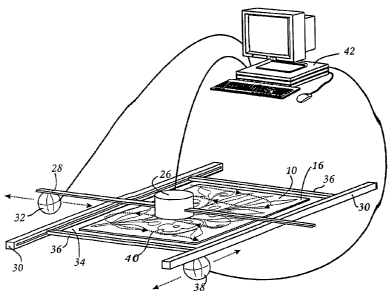
reproduction having finer detail than is available by embossing. Accordingly,
the ratio of the width of an element to the height of the element in an
embossing die is preferably less than 1.
[00150] Once the mold is prepared, the mold may then be used for
creating one or more reproductions 18 using a continuous sheet of substrate
or a plurality of individual sheets of substrate. The substrate may be any
substrate capable of being molded. Preferably, the substrate is a thermo-
formable plastic or cellulose based (e.g. paper, cardboard, paper mache).
The thermo-formable plastic is preferably poly vinyl chloride, polystyrene,
neoprene, polyethylene or PET and, preferably, is PVC and, most preferably,
is polystyrene. One advantage of the use of neoprene is that neoprene may
be reversibly deformable and, accordingly, can be reused in the process_ It
will also be appreciated that the substrate may be an irreversibly deformable
thermo-plastic such as poly vinyl chloride or polystyrene. In such a case, the
thermo-formable plastic may be recycled by grinding the used substrate as is
known in the art.
[00151] The thermo-formable plastic substrate may have a thickness
from 0.002-0.02 inches, preferably from 0.005-0.015 inches, more preferably
from 0.008-0.012 inches. Alternately, the substrate may be porous such as
CA 02569002 2006-12-20
WO 2006/045178 PCT/CA2005/001579
-32-
paper or cardboard. In such a case, the substrate is preferably from 0.002-
0.025 inches thick, more preferably 0.005-0.02 inches and, most preferably
0.008-0.015 inches thick. A substrate is preferably considered to be porous if
it will allow a flow of more then 0.1 cubic inches,of gas per square inches of
substrate per minute therethrough when a vacuum of 25 inches of mercury
apply to the substrate.
[00152] In order to enhance the pressure/vacuum molding of a porous
substrate, a coating is preferably applied to ,the porous substrate or a
nonporous substrate provided to make the porous substrate essentially gas
impermeable so that it can be vacuum formed and/or pressure formed. The
coating may be a compound such as ethylene vinyl acetate, which is applied
to the paper or, alternately, a gas impermeable layer such as a
thermoformable plastic, vapor deposited silicon monoxide or dioxide, or a
thermoset plastic and may have a thickness of 0.0002 to 0.010 inches, rnore
preferably 0.005 to 0.005 inches, and most preferably 0.001 to 0.003 inches.
The porous substrate is preferably in intimate, contact with a gas impervious
layer (e.g., an elastomeric material such neoprene) such that pressure and/or
vacuum may be applied to the cellulose based substrate such that the
substrate is forced into intimate contact with a mold, thereby causing the
cellulose based substrate to take on the shape of the mold, which may be a
three dimensional representation of an original piece of art. The nonporous
sheet also takes on the configuration of the surface of the mold during the
molding operation and provides structural strength to the porous substrate to
assist in durability of the resultant reproduction. Alternately, the nonporous
sheet may be removable from the porous sheet once the porous sheet has
been molded. For instance, a neoprene sheet could be "electrostatically
adhered" to the porous sheet and removed after the image has been formed.
[00153] It will be appreciated that if additional rigidity of the topog raphy
is required, that the rear surface of the molded substrate (i.e., the non
image
bearing surface) of the molded substrate, may be filled in with a casting
material, such as plaster or the like.
[00154] Prior to applying a topography to the substrate, an image of the
CA 02569002 2006-12-20
WO 2006/045178 PCT/CA2005/001579
-33-
object is preferably first applied to the substrate. For example, the Image
rnay
be applied by printing a two-dimensional image on the substrate by any
means known in the art, including one or more of offset lithography, silk
screening, spray coating, ink jet printing, or dye sublimation printing.
Subsequently, the substrate is subjected to the molding operation. The irnage
printed on the substrate is preferably aligned with the topography of the
nnold
by any means known in the art. For example, if the substrate is the same size
as the mold, then by aligning the outer edges of the substrate with the rnold,
the image and the substrate may be aligned with the features of the
topography that match the image.
[00155] The substrate may then be placed in a mold and pressure
and/or vacuum applied so as to form a topography or relief pattern in the
substrate. Prior to or during the molding operation, the substrate may be
treated to reduce the rigidity of the substrate permitting the substrate to
better
conform to the topography of the mold without tearing or otherwise damaging
the substrate. For example, the temperature of the substrate may be raised
to permit the substrate to more easily flow into or be pressed into the
topography of the mold. Alternately, one or more chemicals would be applied
to the substrate to temporarily reduce the rigidity of the substrate. For
example, polystyrene, poly vinyl chloride or ABS may be exposed to methyl
ethyl ketone (MEK). The MEK results in the thermo-formable plastic
temporarily softening thereby enhancing the molding operation. Alternately, if
the substrate is cellulose based (e.g., paper or cardboard) the substrate. may
be exposed to steam prior to or during the molding process. It will be
appreciated that an external heat source, such as electric heating coils, may
be used in conjunction with steam to heat the cellulose based substrate and
that the substrate may be exposed to water and then heated. Such
treatments result in the substrate being able to bear finer detail and also
enhance the lifetime of the molds that are utilized. Alternately, a celf ulose
base substrate could be coated with a polyester resin. The polyester resin
will
result in the cellulose based substrate being temporarily more pliable. During
the molding operation, if heat is applied, the resin will cure. As the resin
CA 02569002 2006-12-20
WO 2006/045178 PCT/CA2005/001579
-34-
cures, the substrate hardens. Accordingly, the use of a polyester resin or the
like will result in a molded substrate wherein the image is more durable.
Alternately, cellulose binders such as corn starch -could be utilized.
[00156] Figures 12 and 13 exemplify a method of molding a porous
substrate. As shown therein, a sheet of pressure or vacuum deformable
"'
nonporous material, such as neoprene, 82,, and ,a sheet of porous substrate
I A.
84 are preheated, such as being placed in a heating unit between electrical
heating elements 86 and 88. A source of steam.90 is used to expose porous
cellulose based substrate 84 to steam. For example, injection nozzles may
be provided intermittently between heating elements 86, 88. Once porous
substrate 84 is heated and softened by the steam, (e.g. for a preset time o'r
to
a predetermined temperature), porous substrate 84 together with deformable
nonporous sheet 82 is transferred to a molding station 92. As shown in
Figures 12 and 13, molding station 92 comprising a mold 94, which is
positioned in support frame 96. An air pressure delivery vessel 98 (which
may comprise a manifold) is an airflow communication where the pressure
source 100 (which may be a pump). Once sheets 82, 84 are placed in
molding station 92, pressure delivery vessel 98 is secured in position with
respect to support frame 96 so as to create an airtight chamber above sheet
82. Pressure source 100 may then be actuated which forces air pressure
down passage 102 the cavity 104 within the air pressure delivery vesse=I 98
thereby causing nonporous sheet 82 to press against porous substrate 84
thereby causing the porous substrate to take on the shape of relief pattern 72
of mold 94. As the air pressure in cavity 104 forces the porous substrate 84
to be deformed to the shape of relief pattern 72, air 106 which is positioned
between substrate 84 and relief pattern 74 escapes through holes 78- In
vacuum molding operations, the theoretical upper limit of vacuum of which
can be provided is 15 psi. In contrast, the pressure that can be used in the
process Figures 12 and 13 can be in excess of the 15 psi available frorn the
atmosphere in vacuum molding operations. Accordingly, greater forces can
be applied to substrate 84 then by means of a vacuum alone. Hence, greater
detail in resolution can be achieved than with vacuum molding. Preferably,
CA 02569002 2006-12-20
WO 2006/045178 PCT/CA2005/001579
-35-
the pressure source 100 is activated until the nonporous substrate 82 has
sufficiently cooled to enable substrate 82 to retain the deformed shape.
Alternately, if a curable resin is applied to the porous substrate, the
pressure
source may be actuated until the resin has cured sufficiently to permit
substrate 84 to be removed from the mold without essentially'any damage to
the topography formed in substrate 84. It will be appreciated that if a resin
is
applied, a nonporous substrate 82 may optionally not be used.
[00157] An alternate molding operation is shown in Figures 14 and 15.
As shown therein, only porous substrate 84 is subjected to heating and steam
treatment prior to insertion in molding station 92. Porous sheet 84 is
transferred to molding station 92 at which time nonporous sheet 82 is
provided thereover. A pressure molding operation as depicted in Figure 13
may now proceed. Alternately, a pressure and vacuum forming operation
may be conducted. Referring to Figure 14, mold station 92 is provided with a
vacuum delivery vessel 108, which is in airflow communication with a vacuum
source 110 (e.g. a vacuum pump) such as by passage 112. During operation,
in addition to the pressure that is applied via cavity 104, vacuum pump 110
draws air through pump cavity 114 via passage 112. Accordingly, vacuum
source 110 is actuated so as to evacuate vacuum delivery vessel 108 thereby
causing negative pressure in cavity 114 which draws air 116 through holes 78
thereby causing nonporous sheet 82 to apply force to the porous substrate 84
causing it to deform to the shape of the relief pattern 72. Once again, the
pressure source 100 and the vacuum source 110 may be operated for a
predetermined amount of time or otherwise is taught herein. As the pressure
which could be used in this process can exceed the 15 psi available from the
atmosphere when operating a vacuum molding process, greater force can be
applied to the substrate and hence greater detail of resolution can be
achieved then the vacuum molding alone. For example, by using a
combination of vacuum and pressure molding, the effective force imparted to
the substrate by the pressure and vacuum created by vacuum source 110 and
pressure source 100 can exceed 29/30 inches of mercury.
[00158] In accordance with a further manufacturing operation, it will be
CA 02569002 2006-12-20
WO 2006/045178 PCT/CA2005/001579
-36-
appreciated that substrate 84 may be subjected only to vacuum molding.
Such a process is exemplified in Figures 16 and 17. As shown therein,
porous substrate 84 is heated and then transferred to molding station 84
where a nonporous layer 82 is placed on top of substrate 84: The substrates
82, 84 are secured in the molding station by any means known in the art, such
as by clamping member 118. The vacuum ',molding process may then
proceed as known in the art.
[00159] It will be appreciated that in an alternate embodiment, different
modifications and combinations of these moldirig techniques may be utilized.
In addition, if the substrate is thermoformable, no steam needs to be provided
during the heating operation. In addition, the substrate may not be preheated
but may alternately be heated only in molding station 92. In addition, it will
be
appreciated that, if the substrate is porous, that a nonporous substrate or
layer may be associated with the porous substrate prior to or subsequent to
the insertion of the porous substrate into a molding station in 92. For
example, the porous substrate (e.g. paper) could be laminated to a thin sheet
of poly vinyl chloride or polystyrene prior to any pretreatment steps.
Alternately, the thin sheet of poly vinyl chloride or polystyrene could become
laminated to the porous substrate during the molding operation. The porous
substrate could be mechanically mounted to the nonporous substrate due to
the heat and pressure that the substrates are exposed to during any
pretreatment step as well as during the molding operation. Alternately, an
adhesive, which may be heat activated, could be applied between the porous
substrate and the nonporous substrate so as to produce a laminated
reproduction whereby the nonporous substrate is securely fixed to the porous
substrate.
[00160] In accordance for another aspect of the instant invention, the
temperature of the substrate in the mold is controlled so as to provide more
uniform heating and/or cooling of the substrate. In order to produce an
accurate molded reproductive, the substrate must be sufficiently pliable so as
to confirm with the configuration in the surface of the mold. If the
temperature
is too low, then the substrate may not deform so as to come into full contact
CA 02569002 2006-12-20
WO 2006/045178 PCT/CA2005/001579
-37-
with all portions of the surface of the'mold. Alternately, if the tem'perature
is to
high and the substrate is a thermoformable plastic, then the plastic will tend
to
flow to the lower depressions in the mold -thereby resulting in a molded
reproduction wherein the thickness of the substrate is uneven and may have
holes therethrough. In order for the reproduction to also accurately mirror
the
topography in the surface of the mold, the rigidity of the substrate must
increase after a pressure and/or vacuum molding operation prior to removing
the substrate from the mold. According to this aspect of the invention, a
vacuum and/or pressure molding operation is controlled so that each portion
of a substrate is subjected to similar heating and/or cooling. Accordingly,
all
portions of the molded reproduction may be of, the same, or essentially the
same, quality. In particular, the quality of the ,substrate rnay be
sufficiently
uniform that so no deviation in the resolution of the topography is visible to
a
person.
[00161] Accordingly, in one embodiment, a series of cooling zones are
incorporated into a mold such that the amount of cooling provided to each
zone of the mold, and therefore the temperature of each zone of the mold,
can be individually controlled. For example, in a vacuum molding operation, a
heating element (e.g., an oven) may be provided. The vacuum mold may be
passed underneath the heating element to heat the substrate while a vacuum
is applied to the image surface of the substrate. For example, the oven may
be stationary and the vacuum mold, with the substrate attached, may be
placed underneath or into the oven by traveling in a first direction. The
vacuum mold and substrate may be removed from the oven in the reverse
direction frorn which the mold was inserted. Accordingly, the leading edge of
the substrate which first enters the mold is subjected to heating for an
additional amount of time. This additional amount of time, taking into account
the thickness of the substrate, may be sufficient for the leading edge of the
substrate to undergo excessive heating resulting in degradation of the molded
substrate. Conversely, the trailing edge (the last portion of the substrate to
enter the oven) may not be heated for sufficiently long to obtain full contact
between the thermoplastic substrate and the mold. By providing different
CA 02569002 2006-12-20
WO 2006/045178 PCT/CA2005/001579
-38-
cooling zones in the mold, different temperature regions of the mold can be
created in an axis oriented perpendicular to the movement of the vacuum
mold thereby compensating for the differential heating which would otherwise
be imparted to the substrate by the oven. It will be appreciated that, in an
alternate embodiment, the vacuum mold may be stationary and the oven may
be movable. Alternately, both the oven and the mold may be moveable
relative to the other.
[00162] Alternately, or in addition, a series of heat shields, preferably
aluminurn heat shields, may be installed behind the heating elements of an
oven to create more uniform heat distribution to the substrate during the
heating process. Preferably, aluminum heat shields are utilized as this will
result in the reduction of the radiant heat lost from the oven thereby
allowing
the electric heating elements to operate at a lower temperature, which will
also aid in increasing the uniformity of heating and reducing the energy
consumption of the operation.
[00163] An example of a mold with different cooling zones is shown in
Figures 18 and 19 wherein mold 70 is mounted on top of aluminum cooling
plate 120. Aluminum cooling plate incorporates a series of thin posts 122 and
a series of slots 124 which extend between thin posts 122. When mold 70,
which may be made from an epoxy, metal, ceramic or other material known in
the art is brought into contact with cooling plate 120, thin posts 122 contact
the rear surface of mold 70 thereby serving to transfer heat from mold 70 to
mold cooling plate 120. During vacuum and/or pressure molding, slots 124
serve as channels to allow air 128 to be drawn or forced through holes 78 of
mold 70 and to exit cooling plate 120 through one or more end holes 126.
[00164] In order to provide differential cooling to different portions of
cooling plate 170, a plurality of cooling fins 130, 132, 134, 136 may be
provided at spaced apart locations on the bottom surface of cooling plate 120.
At least one, and preferably each of cooling fins 130, 132, 134, 136 is cooled
by forced convection. Preferably, each cooling fin is provided with its own
cooling fan 138, 140, 142, 144 which are preferably individually controlled.
It
will be appreciated that some cooling fins may be cooled by a single fan and,
CA 02569002 2006-12-20
WO 2006/045178 PCT/CA2005/001579
-39-
alternately, that some of the fans maybe controlled as a group. By varying the
speed of fans 138, 140, 142, 144, differential cooling may be applied to
different portions of cooling plate 120. It will be appreciated that different
portions of the mold may be cold by alternate means, such 'as by providing
cooling flow passages through cooling plate 120 and/or mold 70 (as
exemplified in Figure 21) or that any other cool'ing technique known in the
molding art may be used. A cooling fluid (e.g. a chilled refrigerant, which
may
be liquid or gas) may be passed through such tubes.
[00165] In operation, a sheet of thermoformable plastic 82 may be.held
against mold 70 by any means known in the art such as clamping member
118. Heating oven 150, which has electric heating coils 152, or any other
heat source known in the art, moves across mold 70 in a first direction of
travel as represented by arrow 146. The oven stops when it is positioned
above mold 70, where it stays for a preset amount of time or until a sensor
confirms that substrate 82 has reached a preset temperature or until an
operator otherwise determines that oven 115 has been in position for a
sufficient amount of time or any other method known in the art, at which time
oven 150 moves in the reserve direction of travel, as represented by arrow
148, until it reaches a position where it is not positioned above mold 70. As
such, it will be appreciated that oven 150 dwells above mold 70 above cooling
pin 136 for a greater period of time then it dwells above cooling pin 134.
Similarly, oven 150 dwells above mold 70 above cooling pin 134 for a greater
period of time then oven 150 dwells above cooling pin 132 and, similarly,
oven 150 dwells above mold 70 above cooling pin 132 for a greater period of
time then above cooling pin 130. Accordingly, the portion of substrate 82
above cooling pin 136 maybe heated to a substantially greater temperature
than the portion of substrate 82 above cooling pin 130.
[00166] The size, configuration, and/or orientation of cooling pins 130,
132, 134 and 136, and/or the amount of forced convection or cooling provided
thereto, may be adjusted so as to maintain a uniform, or a more uniform
temperature in all portions of substrate 82. Preferably, cooling fins extend
perpendicular to the direction of motion of oven 150. It will be appreciated
CA 02569002 2006-12-20
WO 2006/045178 PCT/CA2005/001579
-40-
that each cooling fin 130, 132, 134, 136 may comprise a plurality of
individual
cooling fins that are arranged in a line that extends perpendicular to the
direction of travel of oven 150. Alternately, for example, fan 144 may have a
larger fan blade than fan 138 and/or it may be operated at a higher rpm so as
to provide more cooling air to cooling fin 136 than is provided to cooling fin
130 by fan 138. Alternately, or in addition, the surface area of cooling fin
136
may be greater than the cooling area of pin 130. It will also be appreciated
that no cooling fin may be positioned where cooling fin 130 is shown as being
provided in Figure 20. By using any one or more of these variations, the
cooling rate of the mold adjacent cooling fin 136 where oven 150 has the
greatest dwell time is greater there by allowing greater cooling to the
portion
of substrate 82 above cooling thin 136.
[00167] Preferably, the variation in temperature between any portions of
substrate 82 would be no more than 25 F, or preferably no more than _ F,
and most preferably no more than 15 F if the substrate is about 0.01 inches
thick. It will be appreciated that the temperature differential that is
utilized
may be selected based upon the thermoformable substrate that is utilized
during the molding process. For example, it has been found that if the
temperature variation across the mold is less than 25 F, that a sheet of poly
vinyl chloride which is 0.01 inches thick will result in a reproduction 18
having
uniform texture across its surface whereas if the substrate is 0.1 inch thick
polystyrene, similar uniformity is obtained when the ternperature differential
of
the substrate during the molding process is less than 15 F.
[00168] In the embodiment of Figures 21 and 22, cooling channels are
provided in mold 70 itself. As shown therein, a series of groves 154, 156, 158
and 160 are provided in the under side of mold 70, such as by machining.
Vent holes 78 are provided in mold 70 such that none of them pass through or
otherwise interfere with any of the grooves. Mold 70 is mounted on base 162.
Mold 70 and base 162 are configured such that an angular space or cavity
164 is provided. For example, base 162 may be provided with a raised ridge
on which mold 70 seats. During vacuum molding, or combined pressure and
vacuum molding, air is withdrawn through holes 78, through angular space
CA 02569002 2006-12-20
WO 2006/045178 PCT/CA2005/001579
-41 -
164 and through one or more vent holes 126. A series of valves 168, 170,
172 and 174 are preferably used to control the flow rate of coolant through
grooves 154, 156, 158 and 160 respectively. - The outlets 176, 178, 180 and
182 of the grooves preferably lead to a common sump or other heat
exchanger to maintain the temperature of, the 'coolant preferably within a
predetermined range. Preferably, the temperatu re of the coolant is
maintained between 35 - 100 F, more preferably 45 - 75 F, and most
preferably 55 - 65 F. Any coolant known in the art may be utilized. The
amount of coolant delivered to each region of -mold 70 may accordingly be
varied so as to maintain a more uniform tem"perature in substrate 82 as
referred to previously. It will also be appreciated that the coolant that is
provided to'each zone may be in a separate flow loop wherein each coolant is
at a different temperature. Accordingly, instead of varying the flow rate of a
common coolant through each of the grooves, each groove may be supplied
with a coolant at a different temperature thereby perrnitting a similar flow
rate
through each groove. Alternately, one or more grooves may be provided with
a coolant at a different temperature and the flow rates individually
controlled
so as to provide a desired temperature profile to mold 70 so as to produce a
uniform or essentially uniform temperature in substrate 82 as referred to
herein. It will be appreciated that a combination of different cooling methods
may be utilized to cool a single mold 70 during the molding operation.
Accordingly, for example, both cooling pins and grooves could be provided.
[00169] In accordance with another aspect of the instant invention, one
or more texturing materials may be provided to at least one portion of the
substrate so as to enhance the appearance of the reproduction 18. This
aspect of the invention may be used if the substrate is not resized from an
original, or if a substrate is resized but the same scale factor is used for
all
axis or if the reproduction in not textured. The texturing material may be one
or more of metal foil, metal particles, ground clear glass, fragmented clear
glass, ground coloured glass, fragmented coloured glass, clear silicon,
coloured silicon, wood particles in a binder, and stone particles in a binder.
By providing such texturing material, the image surface of reproduction 18
CA 02569002 2006-12-20
WO 2006/045178 PCT/CA2005/001579
-42-
may more closely recreate or simulate diamonds, (e.g. the use of crushed
glass, crushed cubic zircoriium or crushed industrial diamonds), elements
which are made of metal (by using metal foil or metal particles), wood (by
using wood particles and/or fine wood dust preferably in a binder), stone or
concrete (by using stone particles preferably a binder), and 'cloth, fine
cloth
fibers and/or leather to simulate clothing, shoes or other items made from
these materials.
[00170] Referring to Figure 23, substrate 184 has an art image 186 that
has been printed thereon. Adhesive 188 has been provided on a plurality of
regions of the image bearing surface of substrate 184, such as by being
printed thereon. In particular, the adhesive 188 has been applied in regions
190, 192, 194 and 196 where textural enhancement is desired. The adhesive
may be any suitable adhesive known in the art.' The adhesive may be a water
based air dried adhesive such as 3M FastbondTM, and other air dried adhesive
such as Silalph 340TM, a heat activated adhesive such as ethylene vinyl
acetate (EVA) or an ultraviolet light curable adhesive such as Noelle UV
17T"[00'171] Once the artwork adhesive is applied and ready to accept one or
more texturing materials, the texturing materials may be applied by any
means known in the art. The materials may be applied only to the regions to
which the adhesive has been applied. Alternately, the texturing material
maybe applied to the entire surface or a substantial portion of the surface of
substrate 184. In such a case, the textural material will only remain in place
where it contacts adhesive 188. The remaining portion of the texturing
material may be removed, such as by air borne transport and r.ecycled. Other
techniques such as electrostatic flocking may be used.
[00172] In the embodiment of Figures 24A-24D, a heat activated
adhesive is utilized and several different techniques are exemplified. Each of
these techniques may be used individually, or in any combination or sub-
combination. At station 200, metal foil 202, which is provided on a plastic
substrate 204, is applied to region 196 by passing the metal foil 202 and
substrate 184 between motorized rollers 206. This process creates the visual
appearance of metal in region 196. In station 208, additional texturing
CA 02569002 2006-12-20
WO 2006/045178 PCT/CA2005/001579
-43-
material is provided by electrostatic flocking. At station 208, additional
portions of adhesive 188 are heated by heating element 210. Substrate 184
is then passed between hoppers 212, 216 and ground electrode 214 so as to
create electrostatic fields on the inner surface of,substrate 184.
Accordingly,
finely ground glass powder may be allowed, to adhere to region 190 thereby
creating the visual appearance of diamonds. Finely ground ceramic powder
may be adhered to region 192 thereby creating the visual appearance of a
stone finish. Subsequently, substrate 184 may then be passed to a further
station 218 where a heating element 220 heats,adhesive 188 which is placed
in region 194. At station 218, leather may be applied by rollers 222 to region
194 so as to create the illusion of a leather finish. One or more of the
rollers
may have a textured finish so as to emboss or otherwise deform the leather to
provide a desired finish therein.
[00173] Accordingly, it will be appreciated that different texturing
materials can be provided in different regions to simulate various materials.
It
will also be appreciated substrate 184 after having material applied in
regions
190, 192 may be passed between rollers such that the texturing material
applied to those regions may have a smooth finish_ It will be appreciated that
other application methods may be utilized.
[00174] Subsequently, the printed substrate with the textured material
provided thereon may be subjected to a molding operation, such as vacuum
molding as shown in Figure 26, to create a three-dimensional geometry or
topography of the substrate 184 in addition to the textured material added to
regions 190, 192, 194 and 196. As shown in Figure 26, the texturing material
is placed in molding station 92 so that the rear surface (the non-image
bearing
surface) of substrate 184 is in contact with mold 94. It will be appreciated
that, in such a case, mold 94 may contain a male image that is to be
reproduced in substrate 184. In an alternate embodiment, it will be
appreciated that the image bearing face of substrate 184 may be in contact
with mold 94 whereby a female mold may be utilized. In a further alternate
embodiment, it will be appreciated that the texturing material may be applied
to substrate 184 subsequent to the topography being provided in substrate
CA 02569002 2006-12-20
WO 2006/045178 PCT/CA2005/001579
-44-
184 proving such a case, it is preferred that the texturing material is
provided
by means other than rollers so as not to damage the image formed in
substrate 184.
[00175] In addition to using a molding, operation to prepare the
substrate, the substrate maybe alternate(y be prepared by a computer
directing a machine to apply a variable mechanical force to the substrate so
,, .,,
as to produce a plurality of depths in the ~Z dimension. The variable
mechanical force may be produced by a printing head, such as a dot matrix
printing head, a daisy wheel printing head, by a' plurality of pins or an
eclectic
deformable LCD whereby a computer signal will result in a physically member
contacting and depressing the substrate at different locations. Prior to the
substrate being subjected to the variable mechanical pressure, the rigidity of
the substrate may be reduced as discussed herein, such as by increasing the
temperature of the substrate or the addition of a chemical additive or by
exposure to steam.
[00176] In accordance with this embodiment of the invention, the
substrate may be cellulose based or a therrnoformable plastic and, preferably
is a thermoformable plastic. While the use of molds as discussed herein is
advantageous if a large number of reproductions is required, the use of molds
may be prohibitively expensive if only a,single reproduction is required or,
alternately, a short production run is required (e.g. up to about 100
reproductions). In such a case, a three dimensional topographical relief may
be produced by using, e.g., a dot addressable print head such as those used
in dot matrix printers. By controlling the power applied to each pin or each
part
of the printing head, and the duration during which the power is applied
and/or
the temperature of the substrate, the depth of the relief being produced can
be controlled.
[00177] Preferably, the substrate is first printed with an image, or an
image is otherwise applied to a substrate, prior to producing the three
dimensional topographical map. By moving either the print head only, the print
head and the substrate, or only the substrate, in conjunction with the control
of the firing of the pins portions of the printing head, the desired three
CA 02569002 2006-12-20
WO 2006/045178 PCT/CA2005/001579
-45-
dimensional relief pattern can be created at the appropriate locations on the
image. An alternate printing technique that could be utilized would be to
incorporate an electromagnetically movable member (e.g. a hammer) and a
rotatable die member that incorporates a series geometric shapes. The
electromagnetically member may move with respect to the die member such
that, when an appropriate die member is positioned in an appropriate location
of the substrate, the electromagnetically rnovable member contacts the die
and presses it into the substrate so as to create a relief pattern in the
substrate. Accordingly, the depth of the relief that is reproduced can be
controlled by controlling the power applied to the electromagnetically movable
member and/or the duration during which power is applied to the
electromagnetically movable member, thereby adjusting the force with which
the electromagnetically movable member contacts the die members and the
speed at which the electromagnetically movable member contacts the die
member. By controlling the temperature of the substrate, the depth of the
relief produced in the reproduction can also be adjusted. It will be
appreciated
that this technique may be applied to a substrate that has been molded or a
substrate that has no image printed thereon or wherein the substrate
subsequently has an image applied thereto. The following example are
exemplary and non-limiting.
[00178] For example, as shown in Figure 27, computer 42 controls drive
motors 224 which are drivingly connected to rollers 226. Substrate 184
passes between rollers 226 and 228. Accordingly, computer 42 can control
the rate of travel and direction of travel of substrate 184. Computer 42 also
controls motor 230, which is drivingly connected to print head 232, which has
a plurality of pins 234. Motor 230 may be used to cause print head 232 to
travel transversally, in the direction indicated by arrow 238, so that print
head
232 may traverse the entire width of substrate 184. As substrate 184 travels
in the direction of arrow 236, substrate 184 passes proximate to heating
element 240, which heats substrate 184. At the same time, heating element
242 may heat drum 244 which may have an outer layer that is made of a
mechanically deformable heat resistant rnaterial, such as neoprene rubber.
CA 02569002 2006-12-20
WO 2006/045178 PCT/CA2005/001579
-46-
Drum 244 is rotated by motor 246 and motor 246 is controlled by computer
42. Thus as thermoformable plastic sheet 184 moves in direction 236, it is
heated to a temperature which allows it to . be, readily deformable without
destruction of the substrate, at which time the pins 234 of print head 232 are
sequentially or systematically fired, as may~ be directed by computer 42, as
the print head 232 is positioned at the required 'locations by computer 42 to
create a three dimensional topograpiiy of, e.g., an original art work. It wil
I be
appreciated that, in an alternately embodiment, print head 232 may extend
across the entire width of substrate 184 and, accordingly, may not require
movement transversely in the direction of arrow 238.
[00179] Accordingly, substrate 184 may first be passed through, e.g. an
ink jet printer, to have an image printed thereon and subsequently through,
e.g., a dot matrix printer for creating a,three dimensional topography at the
desired or required locations on the image printed on substrate 184.
[00180] By moving either the print head 232 and/or substrate 184, in
conjunction with controlling the firing of pins 234 or the like, the desired
three
dimensional relief pattern can be created in sheet 184. After sheet 184 has
the requisite three dimensional pattern formed therein, fans 248, or other
cooling member, may be utilized to cool the substrate, or cure a resin in the
case of a nonporous substrate, so as to make the three dimensional pattern
durable.
[00181] It would be appreciate that if substrate 184 is cellulose based,
then heating element 240 may also be utilized to apply steam to substrate
284 and/or an alternate steam delivery member may be provide. The
cellulose based substrate may optionally have a layer of thermoformable
material adhered to it, or impregnated into it, to assist the mechanically
deformation process and the subsequent retention of the mechanically
deformation.
[00182] In the embodiment shown in Figure 28, print head 232
comprises a rotating die member 250, which has a plurality of shap-es 252,
which are preferable three dimensional shapes, around its perimeter. Print
head 232 also includes at least one and preferably a plurality of firing pins
254
CA 02569002 2006-12-20
WO 2006/045178 PCT/CA2005/001579
-47-
as well as motor 256. The firing pins 254 and rotating die member 250 are
similar to those of daisy wheel printers and typewriters. When a die member
250 having a desired or pre-selected or predetermined three dimensional
shape 252 is positioned at the correct location above the image on substrate
184, computer 42 will cause a single to be sent so that an appropriately
aligned firing pin 254 to cause a selected three dimensional shape 252 to
strike substrate 184 thereby producing a deformation in substrate 184.
[00183] Accordingly, an advantage of this aspect of the invention is that
a substrate, which may be a single sheet or a continuous roll that may after
treatment be cut into individual sheets, may be treated to provide a relief
pattern. It will be appreciated, that the computer 42 may direct the mernber
that deforms the substrate using a work file having XYZ data wherein the XY
data is scaled using a first scale factor, or a first and third scale factor,
and
disclosed herein and the Z data is scaled using a second scale factor as
taught herein.
[00184] In accordance with another aspect with the instant invention, an
alternate method and apparatus is provided for providing enhancements' to a
reproduction. Instead of, or in addition to, providing textural materials to
the
image bearing surface of a reproduction 18, a reproduction of an art work or
other image may have applied to it a plurality of brush strokes or the like so
as
to supplement or enhance those already present in the image printed on the
substrate. In accordance with a particular preferred aspect with this
invention,
an artist may apply a plurality of brush strokes or the like to enhance a work
of
art. These brush strokes may be recorded (captured). Subsequently, these
brush strokes, or a subset thereof, with or without modifying the original
colour
palette used by the artist, may be used to enhance reproductions of the art
work. In one particularly preferred aspect, the art reproductions are
paintings
made from a substrate onto which the visual likeness of the art work is
printed
and which is subsequently deformed so as to have a three dimensional
topography formed therein.
[00185] One advantage of this invention is that instead of producing a
plurality of reproductions that are identical, a plurality of reproductions
that are
CA 02569002 2006-12-20
WO 2006/045178 PCT/CA2005/001579
-48-
more individualized may be produced. For example, the brush strokes added
by the artist produced on a reproduction may be an interpretative variation of
the original work of art. By utilizing these variations or subsets thereof,,
in
combination with different colour palettes, a plurality of individualized
reproductions may be created. A further use of this technique could be the
production of wallpaper.
[00186] Accordingly, the brush strokes and/or palette knife movements
and paint colour selected by an artist manually enhancing the work of art or
creating a work of art may be captured by electromechanically, electro-optical
or other electronic and/or mechanically means and the resultant data stored.
The stored may then be used by a robot, which is configured to be able to
reproduce the brush strokes and/or palette knife movements made by the
artist and to be able to apply the paint colour selections, or variations
thereof,
that were used by the artist. Preferably, the stored art data is manipulated
to
change or vary the colour palette that was selected by the artist so as to
produce the different interpretation, or plurality of interpretations, of the
artwork created or enhanced by the artist. In addition, or alternately, the
stored art data is preferably manipulated to allow a subset of the original
brush strokes, palette knife movements or the like to be used to create or
enhance an artwork. Accordingly, by applying different subsets of brush
strokes, palette knife nnovements and the like to an art work or an artwork
reproduction, a series of unique individual art works or art work
reproductions
can be created from the art data captured from a single artist.
[00187] It will be appreciated that this aspect of the invention rnay be
used with any printed substrate, or a substrate that has been scaled as
disclosed herein, or to a substrate that has had texturing material added
thereto or will have texturing material added thereto, whether or not scaled
as
disclosed herein. Each of these techniques may be combined or a subset
used to create different products. Further, the robot may be programrned to
reproduce any modifications made by a person to a starting image. It will be
appreciated that, in one embodiment, the starting image may be generated
electronically (e.g. on a computer screen) and the starting image printed and
CA 02569002 2006-12-20
WO 2006/045178 PCT/CA2005/001579
-49-
then modified by an artist.
[00188] As shown in Figure 29, an artist 258 uses a brush 260 to
enhance artwork reproduction 18. Alternately, artist 258 can use one or more
of alternate brushes 262, 264, 266, 268 and/or one or more palette knife tools
270, 272, 274, 276, and 278. The artist may apply one or more colours 280,
282, 284, 286, 288. Sensors 290, 292 determine the position, angle, tool and
colour used to create an enhancement and transmit this information to
computer 42 where the art data is stored. Sensors 290, 292 may be any
sensor known in the art that can record the position and type of brush strokes
made by an artist and can record the colour of paint added by an artist with
each brush stroke, and the tool (e.g. paint brush, knife palette, etc) used by
the artist. And example of such a sensor is an -ultrasonic distance sensor, a
laser scanner wherein the laser target is mounted or affixed to the brush or a
pressure tablet mounted below the artwork.
[00189] In an alternate embodiment, the sensor to determine the
position, angle, tool and colour used to create and enhancement can be
incorporation into the brushes and palette knives and can be directly
transmitted to the computer 42 or can be stored within each of the brushes
and palette knife and can be subsequently be downloaded to the computer
42. For example, the paint brush may have a transponder provided therein
and the art work in which the artist is working may have monitors p rovided
there around to record the position of the paint brush as an artist is working
and the type of tool being used by the artist. Optical sensors could be used
to
record the colour of paint that is applied by the artist with each stroke.
[00190] Computer 42 may use magnetic, electronic, electrostatic, optical
or any other storage mechanism to record the data produced by the sensors.
For example, the data may be stored in the hard drive of a computer or
burned on to a CD. The data may be stored in the form of a database wherein
the associated brush position, brush acceleration and bush paint colour are
recorded. Optionally, the colour vector map or bit map of the original artwork
may also be stored at the same database or an associated.
[00191] This aspect of the invention is not restricted to the use of paint
CA 02569002 2006-12-20
WO 2006/045178 PCT/CA2005/001579
- 50 -
brushes and palette knife tools but may be used with any other'equipment
that may be used to apply paint or ink to a substrate or art work
reproduction.
[00192] The complete art data may be then utilized to control a robot to
reproduce the brush strokes, palette knife strokes of the original a rtist, or
a
subset thereof, or a variation thereof, to create a series of different
reproductions. Accordingly, one or more subsets of the art data may be
derived from the original data set to allow the series of enhanced art works
or
art reproductions to be created wherein each art work or art work
reproductions incorporates unique series of enhancements. Alternately, or in
addition, the colours can be altered in combination with the entire data set
of
enhancements, or a series of subsets thereof, to create an even greater
variety of uniquely enhanced artwork reproductions.
[00193] For example, as shown in Figures 30-33, robot 294 is adapted
to be moved in the X, Y and Z axis. Accordingly, X axis drive member 296, Y
drive member 298 and Z axis drive member 300 may be provided. For
example, X axis drive means may comprise a track 328 in which arm
members 326 are received. A motor may be provided at the base of arm
member 326, or elsewhere, for causing arm member 326 to travel
longitudinally in track 328. Similarly, Y axis drive member 298 may also
comprise an arm member 330, which is movable in a track (not shown) by
means of a motor (not shown). Z axis drive member 300 may comprise a
motor to telescope arm 330 upwardly and downwardly with respect to
reproduction 18. Arm member 330 also includes a member 332 to receive a
brush, 306 or other implement. The brush angle is adjustable (as indicated by
arrow 302) and the brush angle is adjustable (as indicated by arrow 304). A
motor may be provided interior or adjacent brush holding member 332 to
control these adjustments.
[00194] Computer 42, or an alter computer, may be programmed with
the art data and rnay include an algorithm to allow the computer to
automatically select the entire data or to create subsets of the data which
are
used in producing reproductions. It would be appreciated that the same or a
similar series of brushes 308, 310, 312, 316 and palette knife tools 316, 318,
CA 02569002 2006-12-20
WO 2006/045178 PCT/CA2005/001579
-51 -
320, 322, 324 which are used by the artist, may be provided and may be
releasably received in brush holding member 332. Preferably, the robot also
includes mechanical member for permitting the brush/palette tool or the like
to
be automatically replaced upon signals provided by computer 42. Figured 34-
37 illustrate the use of different subsets of art data derived from- the
original
data set to allow a series of enhanced art works'.or art work reproductions to
be created, wherein each art work or art work reproductions incorporates a
unique series of enhancements. One or more of each enhanced artwork or
art work reproduction rnay be produced.
[00195] Figure 34 shows a series of enhancements 336, 338, 340, 342,
344, 346, 348, 350, 352 that were created by' an artist and stored as the
original art data set. A subset of these enhancements were then applies to
each of Figures 35, 36 and 37. Thus, a series of uniquely and robotically
enhanced artwork reproductions are created from the original data subset of
the original art enhanced artwork reproduction shown in Figure 34.
[00196] It would be appreciated that it is not necessary to start with an
original work of art that is reproduced. The technique may be used with an
artwork that is computer generated. In addition, the artwork need not be an
original oil painting or water colour. The original artwork may be a design
for
wallpaper, greeting cards or other mass-produced material bearing an artistic
design.
[00197] In addition, it would be appreciated that this technique may be
used by itself or in combination with one or more of the methods to produce a
topography in an artwork, adding texturing materials to an art work or scaling
an artwork as disclosed herein. It would be appreciated that if the
enhancements are provided in addition to the production of a topography,
scaling or the provision of textural materials as disclosed herein, that the
.enhancements and any other techniques may be provided in any particular
order.
[00198] Accordingly, as shown in Figures 29-37, unique art works may
be prepared by having a person apply enhancements to an art work using a
painting implement, capturing digital data representing at least one of the
CA 02569002 2006-12-20
WO 2006/045178 PCT/CA2005/001579
-52-
movements of the person the movements of the painting implern6nt and the
colour of the paint applied to prepare the enhancements and, mechanically
applying at least some of the enhancements produced by the movements to
the reproductions. The captured digital is preferably manipulated to produce
one or more files containing alternate subsets of enhancements and at least
one of these subsets may then be provided to a reproduction as shown in
Figures 35-37. Preferably, a robot is used to mechanically apply the
enhancements.
[00199] In accordance with a further embodiment of this invention, the
substrate may comprise a frame member (e.g.,a planar or fanciful member
that extends around all or substantially all of the perimeter of a substrate)
so
as to produce both the substrate with the image, and optionally
enhancements, a scaled image and/or a textured relief pattern,
simultaneously with a frame for the substrate. Alternately, a frame may be
prepared separate using one or more of the techniques set out herein on a
different substrate and subsequently combined with the reproduction to
produce a final reproduction suitable for hanging on the wall or the like.
[00200] In accordance with another method of the instant invention, it
would be appreciated that the reproduction may be prepared at a different
location from where the original or object is prepared. Accordingly, the work
image may be produced at a first location and stored in a computer readable
file (e.g. a PDF file). The computer readable file may then be sent, such as
by
e-mail to a second location where the reproduction is produced, such as by a
publisher or other person operating the required equipment. Aiternately, one
or more pictures may be taken at a first location and then sent to a second
location where the work file is prepared. The work file may then be used at
that location to prepare the reproduction or the reproduction may be prepared
at a further location. For example, a manufacture of a consumer product (e,"g.
beer, clothing, perfume and the like) may have an advertiseenent prepared
e.g. such as the image shown in Figure 9. This image rnay be a two
dimensional picture or may be a picture that has a topography therein. The
computer readable file may then be e-mailed to a publisher or other operator
CA 02569002 2006-12-20
WO 2006/045178 PCT/CA2005/001579
-53-
of the equipment who may then produce a reproduction as shown in Figure 9
wherein the reproduction includes a topography. The publisher rnay then ship
the reproduction to the person who produced the 'advertisement or the client
who had the advertisement prepared.
[00201] In another embodiment, this method may be used by a company
to print pictures that are taken by,., an individual. Accordingly, instead of
,.,
developing pictures as is known in the art, the pictures may be developed on
a substrate that has a topography. For example, the pictures may be taken on
film and dropped of at a store or laboratory where the film is developed. The
developed film may then be used to produce the electronic data representing
a work image which may then be used in the same location to produce the
three dimensional reproductions. Alternately, the'developed may be converted
to a CD and shipped to a printer. Alternately, the data may be digitized and
sent via e-mail to a printer. Alternately, if aõconsumer is using a digital
carriera, they rnay merely e-mail a digital picture or pictures to the
printer.
Once a work file is obtained, it may be processed by one or more of the
techniques set out herein. Preferably a dot matrix printer or other variable
force application machine is utilized.
[00202] In another embodiment, this technique could be utilized in a
custom portrait studio. For example, a person may attend a studio to have a
picture of themselves or a member of their family or their entire family
taken.
The resulting irnage (whether on film or a digital picture) may then be
utilized
to produce a picture on a substrate wherein the substrate has a relief so that
one or more, and preferably all, of the person or persons or animals or
combination thereof, which are present in the picture, or any other elements
present in the picture, are provided in relief. In order to produce such
reproduction, it is preferred to use the data to directly drive a printing
head or
the like to produce the reproduction, such as is shown for exarnple in Figures
27 and 28. Alternately, the data could be provided to a rapid prototyping
machine which would then produce a three dimensional reproduction of the
family.
[00203] In accordance with the embodiment of Figures 38 and 39,
CA 02569002 2006-12-20
WO 2006/045178 PCT/CA2005/001579
-54- -
composite work 354 comprises a substrate 20 that is provided with a cover
sheet 356 having a mounting surface 358, for being secured to image bearing
surface 24 of substrate 20, and a top surface 360. In the embodiment-of
Figures 40 and 41, a bottom sheet 362 having a mounting surface 364, for
being secured to rear face 25 of substrate 20, and a rear surface 366.
[00204] Cover sheet 356 and bottom sheet 362 may be secured or
releasably secured to substrate 20 by any means known in the art, such as by
an adhesive, by being laminated to each other during the rnolding process in
which substrate 20 is produced.
[00205] As shown in Figures 38-41, cover sheet 356 and bottom sheet
362 each have the same image formed therein as substrate 20. Accordingly,
image surface 24 and rear surface 25 of substrate 20 are in intimate contact.
Preferably, each of cover sheet 356 and bottom sheet 362 are a material that
can provide additional dimensional stability to substrate 20. Alternately,
cover
sheet 356 and bottom sheet 362 may be provided to enhance the durability of
substrate 20 such as by providing a thin coating to prevent surfaces 24, 25 of
substrate 20 from being scratched. If substrate 20 is cellulose based, then
each of cover sheet 356 and bottom sheet 362 are preferably made of plastic
thereby adding water resistance to substrate 20. Accordingly, the composite
work 354 may be used as trading cards (i.e., cards that contain a picture of a
hockey player, basketball player, football player, etc. as well as information
typically appearing on trading cards such as information about the player)
wherein at least a portion of the material is provided in three-dimensions -
e.g., the picture of the player may be a three-dimensional picture, or a team
emblern, or the composite work may be a substrate bearing an Olympic
emblern or a national flag or religious emblem may be created in 3D.
[00206] It will be appreciated that if image substrate 20 has a relatively
low profile, or if sheets 356, 362 are sufficiently thin and/or elastic, then
cover
sheets 356, 362 need not be subjected to any pre-treatment steps to provide
a three-dimensional image therein but may merely be applied over image
bearing surface 24 and conform to the topography of image bearing surface
24 as each sheet 356, 362 is applied. In such a case, sheets 356, 362 may
CA 02569002 2006-12-20
WO 2006/045178 PCT/CA2005/001579
-55-
merely provide a scratch resistant coating of, e.g., plastic and not add to
the
dimensional stability of substrate 20.
[00207] As shown in the further alternate embodiment of Figures 42 and
43, substrate 20 having an image on image bea'ring surface 24 may be used
in packaging. Accordingly, the packaging may have aõthree-dimensional
picture or artwork provided thereon. For example, packaging 368 may ..,
comprise a plurality of panels, including front pahel 370 having a window 372.
Substrate 20 is associated with window 372 so as to cover window 372. For
example, substrate 20 may be glued to outer surface 374 of front panel 370
or, preferably, as shown in Figure 42, is inserted into packaging 368 such
that
image bearing surface 24 is secured to the interior surface of front panel 370
by any means known in the art, such as an atlhesive, tape, or mechanical
retention. It will be appreciated that substrate 20 may be provided in more
than one panel of packaging 368, may comprise or consist essentially of an
entire panel of packaging 368, may be positioned at any location on a panel
of packaging 368 and that a plurality of substrates 20 rnay be provided on a
single panel of packaging 368.
[00208] Packaging 368 may be constructed from plastic, cardboard, or
paper mache and, is preferably made from a cellulose based material and, in
particular, cardboard. While packaging 368 as shown in Figures 42 and 43 is
a cardboard box, it will be appreciated that packaging 368 need not be a box
but may be of any particular shape.
[00209] Preferably, window 372 is positioned such that, when a product
is placed in packaging 368, a portion of the product is visible through window
372. I n such an embodiment, it is preferred that substrate 20 comprises a
plastic which is at Ieast translucent and, preferably, is transparent (i.e., a
clear
plastic). A three dimensional image may be formed in substrate 20. However,
it will be appreciated that substrate 20 may, in an alternate embodiment, have
a two dimensional image printed thereon and a three dimensional image
formed therein. In either embodiment, it will be appreciated that a portion of
the product may be visible through substrate 20.
[00210] In an alternate embodiment, substrate 20 may be used to
CA 02569002 2006-12-20
WO 2006/045178 PCT/CA2005/001579
-56-
provide at least part, and optionally all of the packaging of an,article. For
example, a product may be packaged in bubble packaging, namely a package
that is formed from plastic and surrounds a product, such as an action figure.
Accordingly, the packaging may have a rear portion and a front portion. In
such a case, the front panel of the packaging may comprise a substrate 20
and thereby have a three dimensional image formed therein. Accordingly, the
incorporation of a three dimensional image into the bubble packaging may be
used to enhance the packaging of a product. Preferably, in such an
embodiment, the image substrate has an image printed thereon and a three
dimensional image formed therein. Accordingly, the image substrate
substantially enhances the attractiveness of the packag ing of a product and
enhances the likelihood that the product may be purchased by a consumer.
[00211] In the alternate embodiment shown in Figures 44 and 45,
substrate 20 provides part or all of the cover of publication 370. As shown
therein, substrate 20 is secured to the cover of a book, by means of an
adhesive 188. As shown in Figures 44 and 45, cover sheet 356 is also
utilized. It will be appreciated that a cover sheet need not be used in this
alternate embodiment.
[00212] Due to the forming process, depressions 378 are formed in rear
surface 25 of substrate 20. These depressions form the negative image of the
topography formed in image bearing surface 24. In order to enhance the
durability of substrate 20, depressions 378 may be filled, such as by filling
depressions 378 with plaster, epoxy, silicone or other m ow cost non shrinking
support materials. Accordingly, essentially no hollow spaces may be provided
between rear surface 25 of substrate 20 and the cover of book 370. It will be
appreciated that in a particularly preferred embodiment, depressions 378 may
be filled and cover sheet 356 may be provided.
[00213] In another embodiment, substrate 20 may be used to produce a
distributable or consumer product 380. For example, distributable 380 may be
one or more of product packaging, a poster, a pen, a clock face, a clock body,
a m ug, a calendar, a lamp body, a lamp shade, a vase, a jewelry box,
furniture, an article of clothing, a plate, a hat, a flag, a hang tag and a
panel.
CA 02569002 2006-12-20
WO 2006/045178 PCT/CA2005/001579
-57-
[00214] In order to prepare the distributable, at least a portion of a
substrate bearing a reproduction may be associated with a mounting
substrate. Substrate 20 may be associated with a mounting substrate by any
securing means known in the arts such as an ad hesive, screws and the like.
For example, as shown in Figures 46 and 47, distributable 380 comprises a
clock having a clock face 382 on which substrate 20 is provided and hands
384 are positioned outwards of substrate 20. Accordingly, the clock face 382
is the mounting substrate. Substrate 20 comprises part of the front face of a
clock and enhances the appearance of the clock.
[00215] Alternately, the distributable may be prepared by integrally
forming the substrate as part of a distributable. For example, if the
distributable is a mug, then the mug may be prepared by blow molding,
injection molding, or rotational molding. The mold may have a female version
of a three dimensional image provided in the surface thereof. Therefore, when
the mug is molded, a reproduction is prepared, namely a three dimensional
rnale image is formed as part of the outer surface of the mug. The two
dimensional image or picture 22 may then be provided to the distributable. For
example, a transparency what has the picture pri nted thereon may be aligned
with the topography provided in the distributable and secured to the outer
surface thereof to create a distributable bearing a three dimensional picture
or
image.
[00216] It will be appreciated that the distributable may be prepared from
several parts that are assembled together to form the completed product, e.g.,
a pen that comprises two halves that are screwed together, and substrate 20
may comprise only part of the complete distributable.
[00217] It will be understood that various additions and modifications
may be made to the products and methods disclosed herein and each is
within the scope of the following claims. In particular, it will be
appreciated that
each of the constructions herein may be used in any particular application
disclosed herein.