Note: Descriptions are shown in the official language in which they were submitted.
CA 02569621 2006-12-04
WO 2005/120737 PCT/EP2005/006258
1
Method and system for cleaning a soil containing contaminants
Field of the invention
The present invention relates to the field of soil remediation. The invention
relates to
methods and systems for cleaning soils containing contaminants, and more in
particular to a
method and system for volatilizing contaminants in the soil by thermal
conduction and
effectively and efficiently removing these contaminants from the soil. The
method and system
are in particular characterized in that at least a part of the heat energy
which is obtained by
treating the soil contaminants is recuperated and re-used in the method or
system.
Background
The contamination of surface and near-surface soils has become a matter of
great
concern in many locations. Soil may become contaminated with chemical,
biological, and/or
radioactive contaminants. Material spills, leaking storage vessels, and
landfill seepage of
improperly disposed materials are just a few examples of the many ways in
which soil may
become contaminated. If left in place, many of these contaminants will find
their way into
aquifers, air, or into the food supply, and could become public health
hazards.
There are many proposed methods for removal of surface contaminants, such as
excavation followed by incineration, in situ vitrification, biological
treatment, chemical
additives for deactivation, radiofrequency heating, etc. US patent No
5,337,684 for instance
describes a method and apparatus for removing vaporizable contaminants from
flowable
materials such as liquids, sludge or soil. The contaminated material is
removed from its site
by means of a conveyor, and further introduced into a treatment vessel, where
it will be
heated such that contaminants in the soil will be vaporized, after which this
obtained
contaminant vapor is further incinerated and decontaminated. Although
successful in some
applications, these methods can be very expensive and are not practical if
many tons of soil
must be treated.
A process that may be used to remove contaminants from subsurface soil is a
soil
vapor extraction process. In such process a vacuum is applied to the soil to
draw air and
vapor through subsurface soil. The vacuum may be applied at a soil/air
interface, or the
vacuum may be applied through vacuum wells placed within the soil. The air and
vapor may
entrain and carry volatile contaminants towards the source of the vacuum. Off-
gas removed
from the soil by the vacuum which includes contaminants that were within the
soil is then
CONFIRMATION COPY
CA 02569621 2006-12-04
WO 2005/120737 PCT/EP2005/006258
2
transported to a treatment facility wherein it is processed to eliminate, or
reduce contaminants
to acceptable levels.
In situ thermal desorption may be used to increase the effectiveness of a soil
vapor
extraction process. In situ thermal desorption involves in situ heating of the
soil to raise the
temperature of the soil while simultaneously removing off-gas from the soil.
Heat added to
contaminated soil may raise the temperature of the soil above vaporization
temperatures of
contaminants within the soil and cause the contaminants to vaporize. A vacuum
applied to the
soil allows dragging the vaporized contaminant out of the soil.
One method of heating a soil containing contaminants comprises the injection
of a
heated fluid into the soil.
Such method is for instance described in US patent No 6,000,882. The herein
described method consists of introducing a system of perforated pipes into the
soil. A stream
of hot air is sent through the pipes. The hot air is injected into the soil
through perforations in
the pipes at the level of the pipe perforations. A contaminant vapor is formed
in the soil, which
may be removed from the soil through the perforations in the pipes and
disposed to an off-
gas treatment unit.
A similar system is described in US patent No US 5,228,804. Herein two series
of
perforated pipes are introduced in a heap of contaminated soil that has been
excavated. One
series is applied at the heap basis and is suitable for injecting hot air
through the pipe
perforations into the soil. Another series of pipes is applied at the top of
the soil heap and is
suitable for dragging the contaminant gases together with the percolating hot
air out of the
heated soil. Besides the need to use at least two series of different acting
pipes, which have
in addition to be positioned towards each other in a well-defined way, the
disclosed method
further has the disadvantage that the soil heap always needs to be covered
with an isolating
blanket or the like, to avoid dissipation of contaminant gasses into the
atmosphere.
Furthermore, the described method is not suitable for in situ soil treatment,
and energetic
unfavorable, since a high input of energy is required for effectively heating
the soil.
Another major draw back of the above-described type of method however, is that
hot
air injection into the soil is prone to create vapor flow paths in the soil.
Also, percolation of hot
air through the soil may be hampered by the soil type, such as e.g. clay. As a
consequence,
the hot air is not homogenously distributed in the contaminated soil, but
rather accumulates at
its injection level in the soil; i.e. in and around the pipe perforations.
CA 02569621 2006-12-04
WO 2005/120737 PCT/EP2005/006258
3
Another way of heating a soil consists of heating a soil by thermal
conduction.
Thermal conductive heating of a contaminated soil in combination with the
removal of
contaminant gases from the soil using a vapor extraction system is old in the
art.
Thermal blankets and/or ground heaters that are placed on top of the
contaminated
soil have been applied for conductively heating a soil. US patent N
5,169,263, for instance,
describes a decontamination system wherein the contaminated soil is covered
with a heater
element. The heat generated at the soil surface is conducted and convected
downwardly into
the soil. As the soil temperature rises, contaminants evaporate and flow
towards perforated
pipes provided in the contaminated soil. The flow of contaminant vapor through
the pipes is
encouraged by pressure reducing means, typically a vacuum pump, acting in
cooperation
with the pipes to lower the pressure at or around the pipes. A drawback of
such method
however is that permeability of the soil may limit the effectiveness of the
heating process such
that the heat is not homogenously distributed in the contaminated soil.
Alternatively, systems have been described wherein thermal conductive heating
of the
soil may include resistively (electrically) heating a well casing, which
conductively heats the
surrounding soil. Coincident or separate source vacuum may be applied.
In US patent No 5,244,310, for instance, a method and system for remediation
of
contaminated soil is described, wherein a frame is applied to which a
plurality of heating
elements and vapor collecting elements are connected. The heating elements are
heated by
electrical power supplied from a power supply, and the heat is conducted and
convected to
the soil surrounding the elements. A vacuum extraction system is connected to
the vapor
collecting elements and puts the elements under a negative pressure, such that
contaminant
vapor can be collected and withdrawn out of the soil via the vapor collecting
elements.
From US 2002/0018697 a soil remediation system is known wherein heat may be
transferred to the soil from resistively heated bare metal heater elements.
The heater
elements may be placed within the soil. The system further comprises a vapor
collection
system that consists of a plurality of pipes connected to a vacuum system for
providing a
vacuum to the soil and for removing off-gas from the soil.
US patent N 5,318,116 describes in situ thermal desorption systems and
processes
for treating contaminated subsurface soil with thermal conductive heating
applied to soil from
electrically heated heater wells provided in a casing. The heater wells are
placed in the
contaminated soil where they conductively heat the soil to elevated
temperatures. The heater
wells are connected to a vacuum manifold for collection of the contaminant
vapors. The wells
CA 02569621 2006-12-04
WO 2005/120737 PCT/EP2005/006258
4
are permeable to the vapors which emanate from the soil when heated and are
drawn
towards the heater wells by the imposed vacuum.
A common drawback of the above-mentioned methods however is that they are
relatively inefficient from an energetic point of view. In these methods, a
contaminated soil is
heated, vaporized soil contaminants are extracted out of the soil and
decomposed or
destroyed on site e.g. in a thermal treatment system. However, heating of the
soil as well as
thermally treating the soil contaminants extracted out of the soil are both
processes which
require the input of a substantial amount of energy. The above-mentioned
methods thus
require a large input of energy and therefore bring along large operating
expenses.
The present invention aims to provide a solution to the above-mentioned
problem by
providing a method and system for cleaning a soil containing contaminants
which is more
efficient from an energetic point of view. In particular, the present
invention aims to provide a
nearly closed loop method and system for cleaning a soil containing
contaminants wherein
the energy which is obtained by thermally treating the soil contaminants is at
least partly
recuperated and re-used.
Summary
The present invention relates to a method and a system for cleaning a soil
containing
contaminants. The methods and systems disclosed herein are meant for cleaning
soil from
both volatile and semi-volatile contaminants. The methods and systems
according to the
present invention may be applied for cleaning contaminated soil in situ as
well as ex situ. The
subject invention concerns a nearly closed loop system which makes use of a
vacuum to drag
contaminant gases out of a heated soil. The present method is in particular
characterized in
that the soil is heated by thermal conduction, i.e. without injection of any
heated fluid into the
soil. The present method is also characterized in that energy which is
obtained by thermally
treating the soil contaminants is at least partly recuperated and re-used.
In a first aspect, the present invention relates to a method for cleaning a
soil
containing contaminants comprising the steps of:
- introducing at least one heat-conductive pipe, which is in working condition
under
negative pressure, and provided with perforations in said soil,
- heating said soil by thermal conduction by circulating a heated fluid
through said heat-
conductive pipe thereby obtaining a contaminant vapor, whereby said
contaminant
CA 02569621 2006-12-04
WO 2005/120737 PCT/EP2005/006258
vapor is forced into the heat-conductive pipe through a negative pressure
present
herein,
- further transporting said contaminant vapor in said heat-conductive pipe out
of the
soil, and
5 - incinerating said contaminant vapor in order to at least partly remove
said soil
contaminants.
In a preferred embodiment, the present invention relates to a method,
comprising
heating said soil by thermal conduction to a temperature sufficient to cause
vaporization of
said soil contaminants. Preferably, the soil is heated by thermal conduction
by circulating a
heated fluid through the heat conductive pipe(s) that has(ve) been introduced
in said soil. In
addition to allowing greater removal of contaminants from the soil, the
increased heat of the
soil may result in the destruction of contaminants in situ e.g., contaminants
such as
hydrocarbon and/or chlorinated hydrocarbon contaminants.
In another preferred embodiment, the present invention relates to a method
which
comprises re-using the heat energy obtained by incinerating said contaminant
vapor for
heating said soil in order to vaporize the remaining contaminants in said
soil.
In yet another preferred embodiment, the present invention relates to a method
which
comprises extracting said contaminant vapor out of said soil by creating a
difference in
pressure in said soil. The method preferably comprises forcing said
contaminant vapor into a
heat-conductive pipe by creating a negative pressure in said heat-conductive
pipe. A
pressure difference is preferably obtained by imposing a vacuum to the soil
for reducing
pressure in the soil and for withdrawing contaminants from the contaminated
soil. More in
particular, one or more heat-conductive pipes which are under negative
pressure in working
conditions are introduced in the soil. The present method comprises the step
of forcing said
contaminant vapor into said heat-conductive pipe by creating a negative
pressure in said
heat-conductive pipe. Advantageously, in view hereof, the present method does
not involve
the injection of heated fluid into the soil. The heated fluid remains in the
pipes and
contaminant gases formed in the soil are dragged (sucked) into the pipes due
the pressure
difference between the soil and the pipes, and due to the negative pressure
present in the
pipes.
The combined effectiveness of both heat and vapor flow yields 100% sweep
efficiency, leaving no area untreated, and a destruction/removal efficiency
approaching 100%.
CA 02569621 2006-12-04
WO 2005/120737 PCT/EP2005/006258
6
This occurs because the coolest locations within the treatment zone can be
heated, if desired,
to the boiling points of the compounds, and maintained at such temperatures
for many days.
In addition, the increased heat of the soil and the imposed difference in
pressure also
allows the at least partial in situ incineration of the soil contaminants. In
particular,
contaminants are not only vaporized in the soil but they also partly ignite
and automatically
flare up already in the soil, which greatly improves their removal from the
soil.
The present invention provides a method for cleaning a contaminated soil which
is
very efficient from an energetic point of view. In particular, the method
comprises
recuperating the energy which is obtained by incinerating soil contaminants
and re-using this
energy in the system. The present invention thus requires less input of energy
compared to
traditional methods, is therefore more efficient from an energetic point of
view, and brings
along less operational costs. In a preferred embodiment, the invention relates
to a method
comprising incinerating said contaminant vapor by:
- incinerating said soil contaminants in said contaminant vapor thereby
obtaining
incineration gases and heat energy,
- recuperating said heat energy, and
- re-using said recuperated heat energy for heating said fluid.
The present method is in particular characterized in that the heated fluid and
the
contaminant vapor are intermixed and treated together in order to at least
partly remove said
soil contaminants and to provide heat energy. The obtained heat energy is
recuperated and
re-used for heating the soil wherein soil contaminants may have remained. In a
preferred
embodiment the recuperated heat energy is at least partly re-used for heating
the fluid which
is sent through the soil for conductively heating the soil. Preferably, the
present method
comprises re-circulating at least a part of the heated fluid and at least a
part of said
incineration gasses into the soil to be treated. In particular, incineration
gasses obtained from
incinerating the contaminant vapor are preferably at least partly (as much as
possible) re-
circulated through the contaminated soil.
In yet another embodiment, the present invention relates to a method which
comprises circulating said heated fluid through said soil by introducing one
or more perforated
heat conductive pipes in said soil and by circulating said heated fluid in
said pipes. In yet
another preferred embodiment, the present method further comprises extracting
said
contaminant vapor out of the soil by forcing said contaminant vapor through
the perforations
into the heat-conductive pipes, and further transporting said contaminant
vapor in said pipes
CA 02569621 2006-12-04
WO 2005/120737 PCT/EP2005/006258
7
out of the soil. Preferably at least one heat-conductive perforated pipe is a
threaded pipe. In
yet another preferred embodiment, the present method comprises introducing
said one or
more heat-conductive perforated pipes in said soil by screwing said heat-
conductive pipes in
said soil.
The temperature reached by the soil is an important parameter for the
evaluation of
the cleaning potential of the present method, because it is a determinant
factor for pollutants
decomposition. For that, the present invention provides in another preferred
embodiment, a
method which comprises monitoring the temperature in the soil and at different
places of the
nearly closed loop system.
In yet another preferred embodiment, the present invention relates to a method
which
comprises covering said soil containing said soil contaminants with an
insulation sheet and/or
placing an insulation sheet underneath said soil containing said soil
contaminants. An
insulation sheet on the soil surface minimizes heat loses. An insulation sheet
covers the soil
surface and reduces heat losses from the soil surface.
In another aspect, the invention relates to a nearly closed loop system for
cleaning a
soil containing contaminants comprising
- means for heating said soil comprising at least one perforated heat-
conductive
pipe which is, in working condition, under negative pressure,
- means for forcing a contaminant vapor into said heat-conductive pipe, and
- means for incinerating said contaminant vapor in order to at least partly
remove said soil contaminants present in said vapor.
In a preferred embodiment, the present system further comprises means for re-
using
the heat energy obtained by incinerating said contaminant vapor for heating
said soil in order
to vaporize the remaining contaminants in said soil.
In another preferred embodiment, the invention relates to a system wherein the
means for heating said soil comprise at least one heat-conductive pipe in
communication with
an oxidizer. Preferably, at least one heat-conductive perforated pipe is a
threaded pipe.
In another preferred embodiment, the invention relates to a system, wherein
said
means for forcing said contaminant vapor out of said soil into said heat-
conductive pipe(s)
comprises a vacuum system that is in connection with said heat-conductive
pipe(s).
CA 02569621 2012-07-25
`78471-5
8
In another preferred embodiment, the invention relates to a system,
wherein said means for incinerating said contaminant vapor comprise an
oxidizer that
is in communication with said heat-conductive pipe(s).
In yet another preferred embodiment, the invention relates to a system,
wherein said means for re-using the heat energy obtained by incinerating said
contaminant vapor comprises a piping system connecting said heat-conductive
pipe(s) with said oxidizer.
According to a preferred embodiment, the invention relates to a system
further comprising pressure measuring means, temperature measuring means
and/or
flow regulating means.
According to another embodiment, the invention relates to a system
which further comprises one or more insulation sheets for covering and/or for
being
positioned underneath said soil containing said contaminants.
In a further embodiment, the invention relates to method for cleaning a
soil containing contaminants comprising the steps of: introducing at least one
heat-
conductive pipe in said soil, whereby said pipe is in working condition under
negative
pressure and comprises a perforated outer pipe which is provided with a non
perforated inner pipe of a smaller diameter such that a space is created
between the
inner and the outer pipe, in said soil, heating said soil by thermal
conduction by
circulating a heated fluid through said heat-conductive pipe thereby obtaining
a
contaminant vapor, whereby said contaminant vapor is forced into the heat-
conductive pipe through a negative pressure present herein, further
transporting said
contaminant vapor in said heat-conductive pipe out of the soil, and
incinerating said
contaminant vapor in order to at least partly remove said soil contaminants,
and
re-using the heat energy obtained by incinerating said contaminant vapor for
heating
said soil in order to vaporize the remaining contaminants in said soil.
CA 02569621 2012-07-25
'78471-5
8a
In a still further embodiment, the invention relates to a system for
cleaning a soil containing contaminants comprising means for heating said soil
comprising at least one heat-conductive pipe which is, in working condition,
under
negative pressure, and which comprises a perforated outer pipe which is
provided
with a non perforated inner pipe of a smaller diameter such that a space is
created
between the inner and the outer pipe, means for forcing a contaminant vapor
into
said heat-conductive pipe, and means for incinerating said contaminant vapor
in
order to at least partly remove said soil contaminants present in said vapor,
and
means for re-using the heat energy obtained by incinerating said contaminant
vapor
for heating said soil in order to vaporize the remaining contaminants in said
soil.
The foregoing and other objects, features and advantages of the
invention will become more readily apparent from the following detailed
description of
preferred embodiments which proceed with reference to the accompanying
drawings.
Detailed description of the figures
FIG. 1 is an illustration of an embodiment of a soil remediation system
according to the present invention.
FIG. 2 is an illustration of an embodiment of a soil remediation system
according to the present invention that is embedded in a contaminated soil
heap.
FIG. 3 is an illustration of another embodiment of a soil remediation
system according to the present invention.
FIG. 4 is a cross-sectional view of an embodiment of a perforated pipe
that is used in a soil remediation system according to the present invention.
While the invention is susceptible to various modifications and
alternative forms, specific embodiments thereof are shown by way of example in
the
drawings and will herein be described in detail. The drawings may not be to
scale. It
should be understood, however, that the drawing and detailed description
thereto are
CA 02569621 2012-07-25
'78471-5
8b
not intended to limit the invention to the particular form disclosed, but on
the contrary,
the intention is to cover all modifications, equivalents and alternatives
falling within
the scope of the present invention as defined by the appended claims.
CA 02569621 2006-12-04
WO 2005/120737 PCT/EP2005/006258
9
Detailed description of the invention
The terms "contaminated soil" and "soil containing contaminants" are used
herein as
synonyms and are to be understood as including all types of soils which may be
contaminated with chemical, biological, and/or radioactive contaminants,
including but not
limited to frozen soils, very wet soils, soils with a high clay content, soil
containing coal
residues, sediments, slurry, sludge, contaminated waste, cakes or the like,
etc.,
Heat by conduction takes place when two material media or objects are in
direct
contact, and the temperature of one is higher than the temperature of the
other. Heat
conduction consists of a transfer of kinetic energy from the warmer medium to
the cooler one.
The term "conduction" as used herein is therefore meant to refer to all types
of heat transfer
wherein heat is moved from one (warmer) object to another (cooler) object by
direct contact.
It shall be understood that in the present invention, where heat transfer by
conduction is
referred to, also a very small amount of heat is generally also transferred to
the soil by means
of radiation. It shall therefore be clear that the term "thermal conduction"
as used herein,
refers to a situation wherein the soil is heated by conduction, without
introducing or injecting
any heated fluid into the soil.
The present invention relates to a nearly closed loop system of one or more
heat-
conductive perforated pipes embedded in the soil. For reasons of clarity the
following
description will be directed to a system comprising at least two pipes.
However it should be
clear that the present system may also comprise the use of a single pipe. The
perforated
pipes are in communication with a heat source that circulates a heated fluid
through the
pipes. The method comprises the steps of placing the perforated pipes in the
contaminated
soil, circulating a heated fluid throughout the pipes, elevating the
temperature of the
surrounding soil to a temperature sufficient to cause vaporization of soil
contaminants;
dragging the vaporized soil contaminants from the soil into the perforated
pipes; and treating
the vaporized soil contaminants to remove the soil contaminants. The
contaminants are
drawn to the pipes by imposing a negative pressure in the perforated pipes,
e.g. by
connecting the pipes to a vacuum system.
The present method is in particular characterized in that the vaporized soil
contaminants and the heated fluid are intermixed in the piping system and are
drawn together
out of the soil for further treatment. Intermixture with the heated fluid
improves the removal of
the vaporized contaminants out of the soil: the contaminants are entrained in
the flow of
heated fluid and transported out of the soil. The present method is also in
particular
CA 02569621 2006-12-04
WO 2005/120737 PCT/EP2005/006258
characterized in that the energy which is obtained by thermally treating the
vaporized
contaminants is at least partly recuperated and re-used. In particular, the
present method
comprises a nearly closed loop system wherein the energy which is obtained by
incinerating
the soil contaminants is at least partly re-used for heating the fluid that is
sent through the
5 piping system for conductively heating the contaminant soil. Incineration
gasses resulting
from the incineration of the contaminant vapor may also be at least partly re-
circulated and re-
introduced into the contaminated soil. A part of the incineration gasses may
be removed from
the nearly closed loop system.
The pipes are arranged in a pattern in the contaminated soil so as to achieve
the most
10 uniform heating throughout the pattern. A regular pattern of pipes can be
used, such as
triangular, square, rectangular, hexagonal etc., chosen to substantially cover
the
contaminated area. Triangular patterns are preferred since they provide the
best thermal
efficiency and, in practice, are easy to locate on the soil surface or in a
soil heap. The
temperature in the soil is raised by circulating a heated fluid through the
pipes. A thermal front
moves away from the pipes into the surrounding soil by thermal conduction,
thereby
vaporizing water and contaminants in the surrounding soil. The superposition
of the heat flow
from all the pipes results in a more uniform rise in temperature within the
pattern.
It will be clear that the number of pipes applied in the soil heap, the
spacing, the
relative position of pipes, the distance between the base and the pipes and
the distance
between the pipes and the lateral sides of a soil heap may be varied in
function of the
contamination degree and/or the time desired to complete the process and/or
the type of soil
and/or economic considerations. In a preferred embodiment, the distance
between the basis
of the soil heap and the pipes is comprised between 0.25 and 1 m, and
preferably between
0.35 and 0.6 m. In another preferred embodiment, the distance between two
adjacent pipes in
a layer is comprised between 0.5 and 2 m, and preferably between 0.7 and 1.2
m. In yet
another preferred embodiment, the distance between pipes in two superimposed
layers is
comprised between 0.5 and 2 m, and preferably between 0.7 and 1.2 m.
The pipes preferably comprise pipes made of a heat-resistant material such as
but not
limited to steel, metal, or ceramics. The pipes may be of any desired cross
sectional shape,
including, but not limited to, triangular, rectangular, square, hexagonal,
ellipsoidal, round, or,
ovate. Preferably, the pipes have a substantially ellipsoidal, round, or,
ovate cross sectional
shape. In a particularly preferred embodiment, the pipes have a substantially
round cross-
sectional shape and have a diameter which is comprised between 50 and 200 mm
and
CA 02569621 2006-12-04
WO 2005/120737 PCT/EP2005/006258
11
preferably between 80 and 180 mm. The pipes preferably have a length comprises
between 3
and 30 m meter, and preferably between 6 and 18 m.
In an embodiment, the pipes may be formed with a variable cross sectional
area, so
that greater heat dissipation occurs at certain portions of the pipes
(sections having a smaller
cross sectional area) than at other portions of the pipes. A local high heat
dissipation section
of the pipe may be positioned adjacent to soil that requires extra heat
dissipation, such as wet
soil or sections of soil adjacent to the top and bottom of the pipe. Areas
adjacent to the top
and bottom of a pipe may need extra heating to counteract end loss heat
effects. Selected
portions of a pipe may be formed with sections that have a large cross
sectional area. Large
cross sectional area sections of a pipe may be placed adjacent to an
overburden and/or
uncontaminated soil layers.
In another embodiment, pipes having different diameters may be introduced in a
contaminated soil. For instance a first layer of pipes may have a diameter
that is larger than
the diameter of pipes in a second layer. Ideally, the larger diameter pipes
are at the bottom of
a soil heap to generate greater heat conductivity at the base of the heap of
soil.
In another embodiment, one or more pipes may also be introduced substantially
vertically into a contaminated soil. However, according to other embodiments,
the pipe may
be positioned at any desired orientation from 0 (horizontal) to 90
(vertical) relative to ground
surface. For example, in a soil remediation system embodiment, a pipe may be
oriented at
about 45 to remediate soil adjacent to a geological layer that slopes at
about 45 . The
orientation may be chosen to result in relatively low cost, quick and
efficient soil remediation.
The pipe may also be placed in soil so that a portion of the pipe is below
contaminated soil,
and a portion of the pipe is above the contaminated soil. Heating a section of
uncontaminated
soil below the contaminated soil may prevent fall off in temperature at
interface. The cross
sectional area of the pipe adjacent to contamination interfaces may be small,
or may be made
of a different material, so that more heat is diffused into the soil adjacent
to the interfaces.
Diffusing more heat adjacent to the interfaces may promote a more uniform
temperature
distribution throughout the contaminated soil. The pipe may be drilled in the
contaminated soil
to depths that extend slightly below the contaminated zone. Alternatively, the
pipe may be
driven into the soil by conventional pile driving techniques such as hammers
or ultrasonic
devices. The pipes are not necessarily cemented in and therefore can be
removed and
reused after the remediation process is completed. Depending on the geometry
of the
contaminated zone, the perforated pipe need not be vertical but could be
directionally drilled
CA 02569621 2006-12-04
WO 2005/120737 PCT/EP2005/006258
12
horizontally, or the perforated pipe could consist of a combination of
vertical and horizontal
sections. Alternatively, the perforated pipe could be straight sections
drilled at an inclined
angle.
It will be clear to the person of skill in the art that the number of pipes
may vary
depending on their dimensions and the amount and condition of the soil to be
cleaned from
contaminants.
The perforations in the pipes may be, but are not limited to, holes and/or
slots.
Preferably, between 5 % and 50% of the surface of a pipe is provided with
holes and/or slots.
It is particularly preferred that a large amount of small perforations are
provided on the pipe.
The pipes may have several perforated zones at different positions along a
length of the pipe.
When the pipes are inserted into the soil, the perforated zones may be located
adjacent to
contaminated layers of soil. Alternatively the perforations may be provided
along the complete
length of the pipes.
In another preferred embodiment, the pipes are provided with surface extending
means, such as but not limited to fins, screw blades or the like. The pipes
may have several
threaded zones at different positions along a length of the pipe or
alternatively may be
threaded over their entire length. These threads provide the advantage of
facilitating
introduction and withdrawal of the pipes into and out of the soil.
Furthermore, a larger contact
area may promote dissipation of heat produced into surrounding soil and
improves
homogenous distribution of the heat in the soil.
The pipes are heated by sending and circulating a heated fluid such as high
temperature air and/or gas through the piping. Preferably, the high
temperature air/gas is
heated to a temperature comprised between 300 and 300 C, and more preferably
comprised
between 500 and 750 C. Extremely high temperature can also be employed mainly
depending on the temperature limitations of the perforated pipes. Thus, in
cases where
perforated pipes are used which can withstand extremely high temperatures,
i.e., from 1000
up to 1500 C a corresponding extremely high temperature air/gas supply can be
employed.
The heat is transferred to the soil by thermal conduction and progressively
elevates the soil
temperature. A very small amount of heat will also be transferred to the soil
by means of
radiation. The elevated soil temperature causes the contaminants located
within the
contaminated soil to volatilize thereby producing a contaminated vapor.
According to the present invention, the soil is heated by conductive heating,
which is
particularly advantageous because temperatures obtainable by such heating are
not limited
CA 02569621 2006-12-04
WO 2005/120737 PCT/EP2005/006258
13
by the amount of water present in the soil. Soil temperatures substantially
above the boiling
point of water may be obtained using thermal conductive heating. Soil
temperatures of at
least about 100 C, 125 C, 150 C, 200 C, 400 C, 500 C, 600 C, 700 C, 800 C or
greater
may be obtained using thermal conductive heating.
In yet another preferred embodiment, the present invention relates to a method
which
comprises regulating the flow direction of said heated fluid in said soil. For
that, an additional
piping system may be provided in connection with the pipes for adapting the
flow direction of
the heated fluid in the perforated pipes. Sections of soil adjacent to the
inlet of the pipes may
undergo extra heating compared to section of soil adjacent to the end of the
pipes. In order to
counteract these end loss heat effects the present system may provide means
for at least
temporarily adapting and in particular for at least temporarily reversing the
flow of heated fluid
through the pipes. Thereby, sections of soil adjacent to the end of the pipes
are temporarily
provided with extra heat. As a consequence, a more uniform conduction of heat
throughout
the complete section of treated soil is obtained. For that, the present system
may provide an
extra piping system comprising preferably at least two intercrossing tubes of
which the ends
are provided with regulating valves. By adapting the position of the valves,
the heated fluid
may flow in clockwise or in counterclockwise direction throughout the system
of pipes.
A vacuum system is connected to the pipes for putting the pipes under negative
pressure. The vacuum system should be capable of pulling a vacuum appropriate
for the
particular combination of soil permeability and perforated pipes within a
treatment system.
The vacuum system may be able to pull a vacuum in the range of 50 Pa to
5000Pa. The
vacuum system may be a ventilator or a water sealed pump.
As a result of the imposed pressure difference in the soil, the heated fluid
which is
sent through the pipes will not be injected in the soil through the pipe
perforations but will
remain in the piping system. Consequently, there will be no intermixture of
the heated fluid
with the contaminant vapor in the soil and the formation of vapor flow paths
in the soil is
minimized. Unlike fluid injection in the soil, conductive heating will be very
uniform in its
vertical and horizontal sweep and will result in a homogenous dispersion of
heat through the
soil. This is because the heat energy injected into the soil by the pipes is
uniform over each
pipe. Furthermore, conductive heating creates permeability as a result of
drying and shrinking
of the superheated soil (i.e., >100 C) that develops around each pipe. Closely
spaced vapor
flow paths are created even in tight silt and clay layers.
CA 02569621 2006-12-04
WO 2005/120737 PCT/EP2005/006258
14
By putting the perforated pipes under negative pressure vaporized contaminants
are
drawn from the soil into the piping system. The contaminated vapors do not
move through the
soil to the top of the soil but rather into the perforated pipes and down the
pipes into a further
off-gas treatment unit. Some vapors however may move to the soil surface into
a vapor hold
chamber which is formed in between the soil and a covering, applied on top of
the soil
surface.
The vacuum is maintained throughout the period of heating and for a sufficient
time
after heating to avoid contaminant losses or dispersion. The vacuum will lower
the vapor
pressure of the water in the soil and cause boiling to occur at a lower
temperature than the
normal boiling point at atmospheric pressure. At the same time, the high
boiling point
contaminants will be removed by steam distillation in the presence of water
vapor at a
temperature well below the normal boiling point of the contaminants. This will
occur for all
contaminants that are nearly immiscible in water, since the boiling point of
the mixture of two
immiscible fluids will always be less than the boiling point of either
component by itself.
In the perforated pipes, the vaporized contaminants will be intermixed with
the heated
fluid circulating through the pipes. Advantageously, intermixture of heated
fluid with vaporized
contaminants will not only favor the transport of the vaporized contaminants
out of the soil to
an off-gas treatment unit, such as an oxidiser, as hereinafter described.
Advantageously, an increased soil temperature, the imposed vacuum and
intermixture
with a heated fluid at least partly initiates incineration of the soil
contaminants in situ. The soil
contaminants in the contaminant vapor may at least partly ignite and
automatically flare up
already in the soil.
In a preferred embodiment, the surface of the soil is sealed by an insulation
sheet.
Creating a vacuum below the sheet may cause the sheet to be sucked to the
ground surface
but in any case will reduce the amount of air/gas that is being pulled into
the piping system
from the atmosphere. Thus, substantially only air, soil moisture, and
contaminants in the soil
will be evacuated by the perforated pipes embedded in the soil. By pulling
moisture and
contaminants toward the pipes, the risk of spreading the contaminants is
dramatically
reduced. The insulation sheet also allows to reduce heat loss. An insulation
sheet may also
be provided underneath the soil heap to be treated in order to reduce heat
losses to the
underlying soil.
When the contaminated vapor is removed from the soil, the moisture level in
the
contaminated soil is substantially reduced, preferably to an average moisture
level of less
CA 02569621 2006-12-04
WO 2005/120737 PCT/EP2005/006258
than about 5% by weight, more preferably to an average moisture level of less
than about 2%
by weight, and most preferably to an average moisture level of less than about
1 % by weight.
Soil contaminants are removed from the soil by a combination of vaporization,
in situ
thermal decomposition and oxidation in an oxidizer. The perforated pipes and
the nearby soil
5 are extremely hot and most contaminants drawn into the perforated pipes will
decompose
with a residence time of the order of seconds. An oxidizer may be further
employed for
collecting and/or destroying (incinerating) the vaporized contaminants. The
system of the
present invention can further include means for controlling the amount of
contaminated vapor
that flows from the perforated pipes into the oxidizer. In the oxidizer
contaminants are
10 destroyed down to C02 and water. Preferably, the temperature in the
oxidizer ranges from
600 C to 1200 C and more preferably from 700 C to 900 C. Residence time
preferably
varies from 1 to 5 seconds, and more preferably from 1 to 2 seconds.
In another preferred embodiment the present system comprises a fluid
introduction
piping system that transports a heated fluid to the system of perforated pipes
in the soil. In
15 addition, the invention preferably also comprises supply pipes for
connecting the perforated
pipes introduced in the soil heap with the fluid introduction piping system.
These supply pipes
preferably are flexible pipes.
The present system also comprises a vapor collection piping system that
transports
the heated fluid together with vaporized contaminants out of the soil to a
treatment facility. In
addition, the invention preferably also comprises supply pipes for connecting
the perforated
pipes introduced in the soil heap with the collection piping system. These
supply pipes
preferably are flexible pipes. The collection piping system is in connection
with the system of
perforated pipes embedded in the soil and may be coupled to a vacuum system.
In an
embodiment, the piping may be un-heated piping and/or un-insulated piping.
Vapor
containing vaporized contaminants produced in the soil may initially rise
vertically and then
travel downwardly to a treatment facility (e.g. oxidizer). The initial rise
and subsequent
downward travel allows any condensed contaminant vapor to pass to a liquid
trap or to a
separator of the treatment system without blocking lines of the collection
system. In alternate
embodiments, the piping is thermally insulated and heated. Insulated and
heated piping
inhibits condensation of contaminant vapor within the piping. Having a non-
insulated and non-
heated collection system may greatly reduce cost, installation time, and
complexity of a soil
remediation system.
CA 02569621 2006-12-04
WO 2005/120737 PCT/EP2005/006258
16
The heated fluid and the contaminant vapor streams may be processed by a
treatment facility to reduce contaminants within the streams to acceptable
levels. The
treatment facility may comprise a mass transfer system such as activated
carbon bed, a
reactor system such as a thermal oxidizer, or a combination thereof.
Preferably the treatment
facility is a thermal oxidizer.
In a particularly preferred embodiment, the heat energy which is obtained by
incinerating the soil contaminants in the oxidizer is at least partly
recuperated and re-used, in
particular for heating the fluid which is to be sent through the perforated
pipes. The present
invention thus provides an energetically efficient method for cleaning
contaminant soils: in
particular the present method comprises a nearly closed system wherein at
least a part of the
energy for heating a fluid is provided by the incineration of soil
contaminants. In another
particularly preferred embodiment, the heated fluid and the treated vapor in
the oxidizer are
re-used for circulating through the pipes. For that, these are preferably
collected at the exit of
the oxidizer, and drawn to the entrance of the perforated pipes. Thus, the
injected hot air/gas
is routed through the loop and returns to the oxidizer for reheating and re-
injection into the
soil. In particular, the present invention also comprises a piping system for
at least partly re-
circulating the treated contaminant vapor, and in particular the incineration
gasses obtained
after incineration of the contaminant vapor, into the contaminated soil. A
part of the
incineration gasses may be re-introduced into the nearly closed loop system
via an additional
circuit or piping system. A part of the obtained incineration gasses may be
removed from the
system, e.g. via an exhaust pipe on a collector.
In yet another preferred embodiment, the present invention relates to a method
which
comprises improving the incineration of said soil contaminants by providing a
high energetic
waste and/or a burnable gas and/or solid. In order to have an optimal
incineration process,
additional burnable material such as high energetic waste such as e.g. cokes,
coal ... etc.
and/or burnable gases and/of liquids may be provided to the oxidizer.
In a preferred embodiment, the present invention relates to a method which
comprises
accelerating the incineration of said soil contaminants by providing catalyst
material that
enhances the thermal breakdown of contaminants and accelerates high
temperature
decomposition into simpler molecules. The catalyst may be a metal, metal
oxide, or other
type of catalyst that enhances pyrrolysis or oxidation of contaminants. In an
embodiment, the
catalyst is alumina.
CA 02569621 2006-12-04
WO 2005/120737 PCT/EP2005/006258
17
The present system is designed to allow treatment of soil of 20 to 10000 m3 in
volume.
The entire system can be loaded upon a trailer to be transported from site to
site.
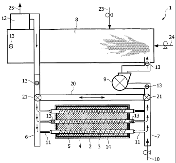
Referring now to FIG. 1, a nearly closed loop system denoted "1" is provided
for
remediation of contaminated soil removed from a soil site. System 1 comprises
a plurality of
substantially parallel extending perforated pipes 3 which have been introduced
in the
contaminated soil 2. The pipes 3 were routed into and then out of the soil
heap 2. The pipes
are located between the adjacent layers of contaminated soil. The pipes are
perforated 4 and
provided with screw blades 5. One end of the pipes is connected to a fluid
introduction pipe 6
that sends a heated fluid through the system of perforated pipes 3 in the
soil. The other end
of the pipes is connected to a vapor collection pipe 7 that transports
contaminant vapor from
the soil to an oxidizer 8. The collection pipe 7 is coupled to a vacuum system
9 and to the
system of perforated pipes 3 embedded in the soil. The vacuum system 9 may
comprise a
vacuum pump which is placed at the outer end of the collection pipe 7. This
pump allows to
impose a negative pressure to the perforated pipes such that vaporized
contaminants which
have been formed in the soil can be drawn from the soil heap into the
perforated pipes and
down to an oxidizer 8. Further, the fluid introduction pipe 6 and the vapor
collection pipe 7 are
interconnected by means a system of tubes. On figure 1 the tube denoted 20 is
a schematic
representation of such system of tubes. Preferably, such system comprises a
couple of
intercrossing tubes, which are both provided with a regulating valve 21 at
each of their outer
ends. By regulating the position of the valves 21, the heated fluid can be
forced to flow in
clockwise or in counterclockwise direction through the system of perforated
pipes 3.
Optionally, a fresh air port 10 is formed at one end of the collection pipe 7
to allow the flow of
ambient air into the nearly closed loop system. Another fresh air port 24 is
formed at the
oxidizer 8 to allow the flow of ambient air into the oxidizer. It will be
clear that additional air
ports may be further provided at other sites in the nearly closed loop system.
Via the air ports
10, 24 outside air is introduced to the evolved vapors to dilute the vapor as
necessary in order
to provide a pure and hot flame at the oxidizer 8. The system further includes
supply pipes 11
for connecting the perforated pipes 3 with the fluid introduction pipe 6 and
the collection pipe
7. Preferably, the supply pipes 11 are flexible, non-insulated, stainless
steel pipes.
In operation, as shown in FIG. 1, hot air/gas is introduced via the fluid
introduction
pipe 6 into supply pipes 11, which in turn feed the hot air/gas to the
perforated pipes 3. Due to
the negative pressure in the perforated pipes 3, the hot air/gas does not exit
the perforated
pipes and is not introduced into the contaminated soil. Heat is conductively
imparted to the
CA 02569621 2006-12-04
WO 2005/120737 PCT/EP2005/006258
18
contaminated soil, namely, volatilizing the contaminants located within the
contaminated soil.
Due to the negative pressure in the perforated pipes, the vaporized
contaminants are forced
into the pipes 3 where they are intermixed with the hot air/gas. The
contaminants at least
partly flare up and are at least partly incinerated in situ and/or further
transported into an
oxidizer 8. In the oxidizer the contaminants are (further) incinerated. Hot
incineration gases
are collected at the exit of the oxidizer stack for instance by using a part
of a collector 12. The
hot incineration gases can be re-drawn to the entrance of the heap of soil 2
through the
introduction pipe 6. Alternatively or in addition incineration gases can also
be re-drawn to the
entrance of the heap of soil 2 through an additional piping system (not shown)
which
connects the collector 12 with the introduction pipe 6 and which transports
incineration gases
to the entrance of the heap soil 2. The heat energy obtained as a result of
the incineration
process is recuperated. The collector 12 is further provided with an exhaust
tube 25, in order
to allow the removal of at least a part of the incineration gases.
In order to measure the temperatures reached by the soil thermocouples 13 are
introduced at different places in the soil heap 2. Thermocouples are also
placed at different
places of the loop system 1 to record the gas temperatures. These
thermocouples are placed
at the entrance and the exit of the oxidizer 8, in the introduction pipe 6 and
the collection pipe
7 and in the pipe front and pipe end of a centrally disposed perforated pipe
3. The
measurements of the thermocouples are recorded.
Referring to FIG. 2 a cross sectional view throughout a heap of contaminated
soil 2 is
illustrated wherein a plurality of perforated pipes 3 have been buried. The
soil heap is at least
partially covered with an insulation sheet 14 in order to reduce heat loss. In
addition, an
insulation sheet 15 is provided underneath the contaminated soil heap 2. The
upper
perforated pipe 16 is not provided in the soil heap but on top of it, in order
to enable to suck
gases from the vapor hold chamber 17 between the contaminated soil heap 2 and
the
insulation sheet 14. This pipe 16 is not connected to the introduction pipe 6
but only to the
collection pipe 7 (not shown). Thermocouples 13 are placed at different places
of the soil
heap for recording soil temperatures. In the embodiment depicted in FIG. 2, a
first layer of soil
is placed on top of the base. A first layer comprising four pipes is placed on
the soil, which is
then covered with an additional layer of soil. A second layer of three pipes
is placed on the
second layer of soil, which is then followed by a third layer of soil. A third
layer of two pipes is
placed on the third layer of soil, which is then followed by a fourth layer of
soil. Finally a
perforated pipe 16 is provided on top of the fourth layer of soil, in the
vapor hold chamber 17
CA 02569621 2006-12-04
WO 2005/120737 PCT/EP2005/006258
19
formed in between the impervious insulation sheet 14 and the top of the soil
heap 2. In
principle, an unlimited number of layers of pipes 3 and soil 2 can be formed.
In between the
layers of pipes additional pipes may be provided (not shown). These pipes form
part of the
piping system for introducing at least a part of the incineration gases in the
soil heap. These
incineration gases have been recuperated form the incineration process in the
oxidizer 8 and
have been collected in the collector 12 before being re-introduced into the
soil heap. In order
to measure the temperatures reached by the soil thermocouples 13 are
introduced at different
places in the soil heap 2. The present system is most efficient with a heap of
soil up to 50 m
tall.
Another embodiment of a system I for remediation of contaminated soil in situ
according to the present invention is provided in FIG. 3. In this embodiment,
the system 1
comprises a perforated pipe 3 which has been drilled substantially vertically
in the
contaminated soil 2. The pipe is provided with screw blades 5, which
facilitates introduction
and removal of the pipe from the soil. Between the threads of the screw
blades, perforations 4
are provided. The perforated pipe 3 is locked off at its lower side by a
substantially cone- '
shaped body 18. This body can be affixed to the pipe by means of welding,
brazing or by
means of thread. One end of the pipe 3 is connected to a fluid introduction
pipe 6 that sends
a heated fluid through the perforated pipe 3 in the soil. The perforated pipe
is further also
connected to a vapor collection pipe 7 that transports contaminant vapor from
the soil to the
oxidizer 8. Additionally, valves (not shown) may be provided at the top of the
perforated pipe
for regulating the circulation and the flow direction of the heated fluid and
contaminant vapor
in the pipe. The collection pipe 7 is coupled to a vacuum system 9 and to the
perforated pipe
3 embedded in the soil. The vacuum system 9 may comprise a vacuum pump, e.g. a
fan,
which is placed at the outer end of the collection pipe 7. This pump allows
imposing a
negative pressure to the perforated pipe 3 such that vaporized contaminants
which have
been formed in the soil can be drawn from the soil heap into the perforated
pipe 3 and down
to an oxidizer 8. Optionally, a fresh air port 10 is formed at one end of the
collection pipe 7 to
allow the flow of ambient air into the nearly closed loop system Via this air
port 10 outside air
can be introduced to the evolved vapors to dilute the vapor as necessary in
order to provide a
pure and hot flame at the oxidizer 8. In order to measure the temperatures
reached by the soil
thermocouples are introduced at different places in the soil heap (not shown).
Thermocouples
13 are also placed at different places of the loop system 1 to record gas
temperatures; i.e. at
the entrance and the exit of the oxidizer 8, in the introduction pipe 6 and
the collection pipe 7.
CA 02569621 2006-12-04
WO 2005/120737 PCT/EP2005/006258
Two thermocouples 13 are further provided in the pipe front to record the
temperature of the
incoming heated fluid and the temperature of the fluid and contaminant vapor
leaving the soil.
FIG. 4 provides a cross-sectional view of an embodiment of a perforated pipe,
used in
a soil remediation system as depicted in FIG. 3. The pipe 3 comprises a
perforated 4 and
5 threaded 5 outer pipe 27 which is provided with a non perforated inner pipe
26. The outer
pipe 27 is locked off at its lower side by a substantially cone-shaped body
18. Inside the
perforated outer pipe 27, a non perforated inner pipe 26 has a diameter which
is smaller than
the outer pipe diameter such that a space 28 is created in between the inner
26 and the outer
pipe 27. The end of the inner pipe 26 is open. The pipe 3 is connected to a
fluid introduction
10 pipe 6 that sends a heated fluid through the perforated pipe 3. The pipe 3
is further also
connected to a vapor collection pipe 7 that transports contaminant vapor from
the soil to a
treatment facility (not shown). The pipe 3 is put under negative pressure by
connecting the
pipe to a vacuum system (not shown).
In an embodiment, heated fluid is sent through the inner pipe 26. The heated
fluid is
15 forced through the open end of the inner pipe 26 to the space 28 in between
the inner 26 and
the outer pipe 27 (see arrows). Due to the imposed vacuum, this fluid will not
be injected in
the soil 2 through the pipe perforations 4 of the outer pipe 27 but will
remain in the pipe 3. The
heated fluid is not intermixed with the contaminant vapor in the soil. By
putting the pipe 3
under negative pressure vaporized contaminants are drawn 19 from the soil
(arrows)into the
20 pipe 3, and in particular into the space 28 in between the inner 26 and the
outer pipe 27,
where they are intermixed with the heated fluid and drawn out of the pipe 3
together with the
heated fluid.
Alternatively (not shown) heated fluid may also be introduced in the pipe 3
through the
space 28 in between outer 27 and inner pipe 26. Contaminants and the heated
fluid may than
be forced via the inner pipe 26 back up to the soil surface and out of the
soil.
In addition, for adjusting the flow direction of heated fluid and contaminant
vapor either
in the outer or in the inner pipe, valves (not shown) are provided on top of
the pipe, preferably
where the pipe is connected to the introduction pipe 6 and the collection pipe
7.
The heated fluid is intermixed with the contaminant vapor inside the pipe 3.
The
contaminated vapors do not move through the soil to the top of the soil but
rather into the
perforated pipes 3 and down the pipes 3 into a further off-gas treatment unit.
Some vapors
however may move to the soil surface into a vapor hold chamber (not shown)
which is formed
in between the soil 2 and a covering 14, applied on top of the soil surface.
CA 02569621 2006-12-04
WO 2005/120737 PCT/EP2005/006258
21
Example
The following example illustrates the cleaning of a heap of 15-20 tons
(metric) of
polluted soil using a method and a system according to the present invention.
The polluted
soil contained amongst other pollutants PAHs (2000 ppm), oils (5000 ppm), and
coal.
For the applied system reference is made to FIG. 1. A "Dragon 15" oxidizer was
used
to burn contaminant vapor and to heat the soil pile. The oxidizer temperature
was
programmed to be around 900-1000 C. Hot gases were collected at the exit of
the oxidizer
stack using a part of a non insulated collector and drawn to the entrance of
the soil pile
through a 8 meters long, 273 mm diameter steel introduction pipe, insulated
with 40 mm
insulation. Nine 1.5 m long non insulated stainless steel flexible pipes of
88.9 mm diameter
were connected to this steel pipe and supplied nine steel threaded pipes
buried in the soil
pile. The threaded pipes of 6m long had a 88.9 mm pipe diameter and a 200 mm
screw
diameter. 15 mm holes 4 were drilled in the pipes 3 every 200 mm on two
diametrically
opposed and alternated lines. The pipes 3 were connected at their end to nine
stainless steel
flexible pipes 11 which brought the contaminant vapor to a 273 mm diameter
partially
insulated steel pipe 7. Then, contaminant vapor was drawn through this pipe 7
to the oxidizer
8. The original fan of the dragon 15 was placed on this pipe 7 to suck gases
from the soil pile.
The pipes were introduced in a soil heap in a pattern as illustrated in FIG.
2. The
upper pipe was not introduced in the soil pile but remained on top of it in
order to allow to
drag contaminant vapour present between the contaminated soil pile and an
insulation cover
provided on top of the soil. The soil heap had a height of 130 cm, the
distance between the
pipes and the basis of the heap comprised 20cm. The width of the soil pile was
220 to 250
cm; the distance between the two pipes (measured from centre to centre)
comprised 50 cm
while the distance between two layers of pipes (measured from centre to
centre) comprised
45 cm. The pile was covered with a 40 mm insulation sheet of aluminum foil,
except at both
ends of the soil heap. An insulation sheet was provided underneath the soil
heap. Building of
the soil pile took approximately 4 hours to two men shoveling, placing screws
and
thermocouples, and one man driving a loader.
During the test the soil temperature and gas temperatures were recorded.
During the
test the concentration of hydrocarbons, 02, CO, CO2 and NOX in the gases going
in and out of
the soil pile were analysed using a gas analyser. These measurements indicated
that while
heating the soil, hydrocarbons were desorbed and sucked into the pipes. These
CA 02569621 2006-12-04
WO 2005/120737 PCT/EP2005/006258
22
measurements also revealed a significant production of CO inside the pile
while burning the
contaminants. Table 1 gives a summary of these results.
TABLE I
Beginning of test End of test
Dry Material % 82,5 to 84,3 % 99,8 to 100 %
Total hydrocarbons (C10-C40) ppm 3200 to 5300 ppm <10 to 13 ppm
Total PAHs (16 EPA) ppm 1800 to 2200 ppm n.d. to 8,9 ppm
The results show that the present system is particularly suitable for cleaning
a contaminated
soil. In particular, coal was present in the contaminated soil, which allowed
the contaminants
to burn in situ and to reach high temperatures of up to 800