Note: Descriptions are shown in the official language in which they were submitted.
- ....~.y,u~~,..,,~M.,....,.,.,, . ..~ ,.
CA 02569908 2008-03-28
1
A TILE FOR USE IN A KNOCK-DOWN PANEL PARTITION SYSTEM
This application is a divisional application of co-pending divisional
application 2,539,496,
filed February 8, 2006 and parent application 2,343,813, filed November 17,
1998.
BACKGROUND AND SUMMARY OF THE INVENTION
The present invention relates to a tile for use in a space dividing or
partitioning system, such as for use in an office environment. More
specifically, the
invention relates to such a system that can be easily assembled and
disassembled
providing numerous space dividing configurations.
A wide variety of office space partitioning or dividing systems are known.
Many such systems include individual pre-assembled wall panels that are
rigidly
interconnected to each other to form a sectioned wall assembly. A pre-
assembled panel
typically includes a factory assembled panel frame that receives a decorative
tile. The
decorative tile typically includes a hook member extending from its back face
surface that is
received in a notched opening in the panel frame. The hook members on each of
the tiles
allow the tile to be hung from the panel frame. In such a system, it is common
to provide a
power distribution system toward the lower end of each wall panel,
incorporating power
receptacles at spaced locations. It is also known to provide power and/or
communication
distribution in each panel substantially at desk height.
While this type of wall construction functions well and has met with success,
it involves certai.n drawbacks. For example, since each of the decorative
tiles includes a
hook member extending from its back face surface, care is required in storage
and
transportation of the individual tiles so as not to bend the hook members on
the decorative
tile. Further, the space occupied by the hook members prevents the tiles from
being
efficiently stacked for shipment or storage, and the tiles must be protected
to prevent damage
which maybe caused by the hook members when the tiles are stacked.
Additionally, since
the panel frames are typically pre-constructed, if the office owner wishes to
reconfigure the
panel system, additional panels having the desired configuration must either
be retrieved
from storage or ordered from the panel manufacturer.
CA 02569908 2006-12-01
la
Field-installed panel systems have been developed to overcome certain
limitations of wall systems based on prefabricated panel frames. These systems
generally
include posts and horizontal support members which are selectively engageable
with the
posts. The posts and horizontal support members are assembled together to
construct the
skeleton of a wall, and tiles are engaged with the posts to form a wall
system. In known
systems of this type, however, a module defmed by a pair of posts and
horizontal support
members interconnected therebetween cannot be reconfigured, such as by
changing the
location of the horizontal support members, without disassembling the entire
module. In
CA 02569908 2008-03-28
2
these systems, if the office owner wishes to add additional horizontal support
members to
the panel frame or alter the location of existing horizontal support members,
the panel
frame must be disassembled and the vertical uprights separated to permit the
positioning
of the horizontal support member therebetween.
Generally, the invention contemplates a tile for use in space dividing or
partitioning system for use in a building having a floor and a ceiling. The
space dividing
system includes a series of interconnected wall modules or panels, each formed
from a
field-assembled panel frame and one or more decorative tiles hung on the panel
frame.
Each panel frame is formed from a pair of vertical posts and at least one
horizontal support
member is positioned between the vertical posts. The vertical posts are
configured such
that each post is common to adjacent wall modules or panels. Each vertical
post may be
formed from one or more post sections interconnected by a splice section. The
post
sections may be either a half post section or a full post section.
Each of the half post sections and full post sections includes a series of
vertically aligned receptacles extending from their front and rear face
surfaces. The
receptacles are spaced and sized to receive attachment members contained on
each end of
the horizontal support member.
Each horizontal support member defines opposed first and second ends, and
is formed from a bottom wall and a pair of opposed sidewalls. The bottom wall
of each
horizontal support member includes a pair of cut-outs extending from both the
first end
and the second end of the horizontal support member. The cut-outs allow the
horizontal
support member to be mounted between a pair of vertical posts that are spaced
apart a
distance less than the length of the horizontal support member without first
separating the
vertical posts.
In accordance with the invention, a tile for use in a panel system in which a
plurality of panels are interconnected to subdivide an open work space,
comprises:
a plurality of tile frame members, wherein each tile frame member defines
a pair of spaced ends, and wherein the tile frame members are positioned
relative to each
other such that each end of one of the tile frame members is located adjacent
an end of
another one of the tile frame members to define a series of corners;
a plurality of corner connectors, wherein each corner connector is located at
one of the corners and includes angularly offset engagement areas which are
CA 02569908 2008-03-28
3
interconnected with adjacent ends of a pair of tile frame members oriented at
a
predetermined angle relative to each other, wherein when a corner connector is
positioned
at each corner defined by the frame members, the corner connectors and the
frame
members form a tile frame having a closed shape having an open interior;
each end of each frame member including a channel formed therein,
wherein the channel is sized to receive an engagement area of one of the
corner connectors
and an attachment flange extending from the channel, wherein the attachment
flange of
each tile frame member is constructed and arranged so as to overlap the
attachment flange
of an adjacent tile frame member and is joined thereto to securely hold the
corner
connectors and frame members together;
a core disposed within the open interior, wherein the core defines edge
areas which overlap the tile frame members; and
an upholstery covering which covers the core, wherein the upholstery
covering is secured to the frame members.
CA 02569908 2006-12-01
4
Various other features, objects and advantages of the invention will be
made apparent from the following description taken together with the drawings.
BRIEF DESCRIPTION OF THE DRAWINGS
The drawings illustrate the best mode presently contemplated of carrying out
the invention.
In the drawings:
Fig. 1 is an isometric view illustrating a knock-down space dividing or
partitioning system in accordance with the present invention;
Fig. 2 is an exploded isometric view illustrating the construction of a panel
frame for use in the space dividing or partitioning system of Fig. 1;
Fig. 3 is an enlarged partial exploded isometric view showing the connection
between a vertical post and horizontal support member of the panel frame of
Fig. 2;
Fig. 4 is a section view taken along line 4-4 of Fig. 2;
Fig. 5 is a partial enlarged section view taken along line 5-5 of Fig. 4;
Fig. 6 is an elevation view of a pair of vertical posts and showing in phantom
the steps performed in attaching a horizontal support member between the pair
of vertical
posts;
Fig. 7 is a partial isometric view illustrating the upper end of a vertical
half
post section of the panel fxame of Fig. 2;
Fig. 8 is a section view taken along line 8-8 of Fig. 2;
Fig. 9 is a section view taken along line 9-9 of Fig. 2;
Fig. 10 is a partial section view taken along line 10-10 of Fig. 9;
Fig. 11 is a section view taken along line 11-11 of Fig. 2;
Fig. 12 is a partial section view taken along line 12-12 of Fig. 11;
Fig. 13 is a top exploded partial section view illustrating the
interconnection
between a pair of vertical half post sections and a corner post for use in the
system of Fig. 1;
Fig. 14 is a partial front elevation view showing the mounting of a tile to
the
panel franie of Fig. 2;
Fig. 15 is an exploded side elevation view showing the mounting of the tile to
the panel frame;
CA 02569908 2006-12-01
Fig. 16 is an enlarged partial isometric view showing the tile mounting
amngement of Fig. 15;
Fig. 17a is an enlarged partial front elevation view showing the insertion of
a
tile retaining hook within aligned openings in the vertical post and the
horizontal support
5 mernber;
Fig. 17b is an enlarged partial front elevation view similar to Fig. 17a
showing rotation of the tile retaining hook into an operative, locking
position;
Fig. 18 is an exploded front elevation view showing the construction of the
frame of a tile member for use in the system of Fig. 1;
Fig. 19 is a partial section view taken along line 19-19 of Fig. 18;
Fig. 20 is an enlarged partial section view showing construction of the tile
frame of Fig. 18;
Fig. 21 is an enlarged partial section view taken along line 21-21 of Fig. 14
illustrating the function of the tile retaining hook;
Fig. 22 is an enlarged partial section view taken along line 22-22 of Fig. 14
illustrating the function of the tile retaining hook;
Fig. 23 is a partial isometric view illustrating the space dividing or
partitioning system of Fig. 1;
Fig. 24 is an enlarged isometric view showing an alternate configuration for
the space dividing or partitioning system of the present invention;
Fig. 25 is a partial front plan view illustrating a pair of panels and various
trim components for the space dividing or partitioning system;
Fig. 26 is a partial top plan view taken with reference to line 26-26 of Fig.
25;
Fig. 27 is a partial section view taken along line 27-27 of Fig. 26;
Fig. 28 is a partial section view taken along line 28-28 of Fig. 25
illustrating
the panel top cap and base cover;
Fig. 28a is an enlarged partial section view showing the interaction between
the panel top cap and one of the horizontal support members;
Fig. 28b is an enlarged partial section view illustrating the interaction
between the base cover and one of the horizontal support members;
Fig. 28c is an enlarged partial section view illustrating the construction of
the
base cover;
Fig. 29 is a partial section view taken along line 29-29 of Fig. 24;
Fig. 30 is a partial section view taken along line 30-30 of Fig. 24;
CA 02569908 2006-12-01
6
Fig. 31 is a partial section view taken along line 31-31 of Fig. 23;
Fig. 32 is an enlarged partial section view showing the interaction between
the comer post and the corner trim;
Fig. 33 is a partial section view taken along line 33-33 of Fig. 23;
Fig. 34 is a partial section view taken along line 34-34 of Fig. 33;
Fig. 35 is a partial section view taken along line 35-35 of Fig. 23;
Fig. 36 is an enlarged section view showing the interaction between the
corner post and the trim cover of Fig. 35;
Fig. 37 is a partial section view taken along line 37-37 of Fig. 23;
Fig. 38 is a partial section view taken along line 38-38 of Fig. 37;
Fig. 39 is a partial side elevation view illustrating the stabilizing
connection
between a vertical half post section and a stationary wall member;
Fig. 40 is a partial section view taken along line 40-40 of Fig. 39
illustrating a
clamp mechanism used to stabilize the half post section;
Fig. 41 is a partial section view taken along line 41-41 of Fig. 40;
Fig. 42 is a partial section view taken along line 42-42 of Fig. 40;
Fig. 43 is a partial front elevation view illustrating a pair of overhead
storage
members mounted to the space dividing or partitioning system of the present
invention;
Fig. 44 is an exploded isometric view showing the mounting arrangement for
one of the overhead storage members of Fig. 43;
Fig. 45 is an exploded isometric view similar to Fig. 44, illustrating a
second
mounting arrangement for one of the overhead storage members;
Fig. 46 is a partial section view taken along line 46-46 of Fig. 43;
Fig. 47 is an enlarged section view taken along line 47-47 of Fig. 46;
Fig. 48 is a partial section view taken along line 48-48 of Fig. 43;
Fig. 49 is an enlarged partial section view of the area identified by line 49-
49
of Fig. 48;
Fig. 50a is a partial front elevation view illustrating the lower portion of
the
space dividing or partitioning system of the present invention;
Fig. 50b is a front elevation view similar to Fig. 50a further illustrating
the
electric wire raceway;
Fig. 51 is a partial section view taken along line 51-51 of Fig. 50a;
Fig. 52 is a partial section view taken along line 52-52 of Fig. 50a;
CA 02569908 2006-12-01
7
Fig. 53 is an exploded elevation view showing the interconnection between
an electrical hanging bracket and the rigid wireway;
Fig. 54 is a partial section view taken along line 54-54 of Fig. 50a;
Fig. 55 is a partial section view taken along line 55-55 of Fig. 50a;
Fig. 56 is a partial section view sharing a wire support clip for use in the
space dividing or partitioning system of the present invention; and
Fig. 57 is a partial section view illustrating a pair of wire clips attached
to one
of the horizontal support members of the system of Fig. 1.
DETAILED DESCRIPTION OF THE INVENTION
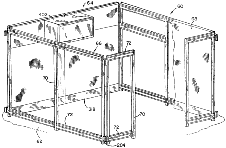
Fig. 1 illustrates a space dividing or partitioning system 60 constructed in
accordance with the present invention. Space dividing system 60 is adapted for
use in a
building having an open space between a floor 62 and a ceiling, and is
operable to divide the
open space into smaller areas. In particular, space dividing system 60 is
adapted for use in a
work place environment to divide the open space into individual work areas,
meeting areas,
reception areas or the like. Generally, space dividing system 60 includes a
series of
interconnected panels 64 that can be joined in numerous configurations to
define the
individual areas. Each of the panels 64 generally includes a field-assembled
panel frame 66
and one or more decorative tiles 68 that are supported on the panel frame 66.
The tiles 68
define the walls of the individual area and often include a decorative
patteno.
Figs. 2-13 illustrate the construction of the panel frames 66. Referring first
to
Fig. 2, each panel frame 66 generally includes a pair of vertical posts 70
joined by at least
one horizontal support member 72. In the embodiment shown, the panel frame 66
includes
both an upper and a lower horizontal support member 72. The vertical posts 70
are spaced
apart by the length of each horizontal support member 72, and the connection
between the
posts 70 and the horizontal support members 72 provides the required rigidity
for the panel
frame 66.
In order to provide a space dividing system 60 that can be assembled and
disassembled to create individual areas having a variety of configurations,
each of the
vertical posts 70 shown in Fig. 2 may be constructed from a pair of individual
post sections
joined together by a splice section. In the panel frame 66 shown in Fig. 2,
the right vertical
post 70 is constructed from two full post sections 74 that are joined together
by a splice
section 76, while the left vertical post 70 is formed from a pair of half post
sections 78 joined
by a splice section 80. Altematively, each vertical post 70 may be continuous
and formed
without splices.
CA 02569908 2006-12-01
8
As shown in Fig. 9, the splice section 76 is received within an open interior
82 defined by the outer walls of the full post section 74. Full post section
74 is formed from
two identical mating outer wall sections 84 that define the generally
rectangular open interior
82. The pair of identical outer wall sections 84 are joined along a pair of
longitudinal seams
86 by a series of spaced welds 88. In the preferred embodiment of the
invention, each of the
outer wall sections 84 forming the full post section 74 is formed from sixteen
gauge cold
rolled steel to provide the required strength and rigidity for the panel frame
66.
As can be seen in Figs. 9 and 10, the splice section 76 includes a series of
web sections 90 that extend outward and create an interference fit with inner
surfaces 92 of
the full post section 74. Each web section 90 includes a tapered portion 94
that allows the
splice section 76 to be inserted into the open interior 82 of the full post
section 74. As
shown in Figs. 2 and 10, the splice section 76 is positioned between the upper
and lower full
post sections 74 such that the splice section 76 securely connects the upper
and lower full
post sections 74 to generally define the complete vertical post 70 to be
utilized in the panel
frame 66. Constructing each vertical post 70 from two separate full post
sections 74 allows
the panel frame 66 to be constructed having either the full height as shown,
or a reduced
height if only one full post section 74 is used.
Referring now to Fig. 8, the half post section 78 is constructed in a similar
manner to the full post section 74 previously discussed. However, the width of
the half post
section 78 is approximately half the width of the full post section 74. In
construction of the
panel frame 66, the full post sections 74 are used to form the vertical post
70 between
adjacent panels extending in the same direction, while the half post sections
78 are utilized
to for;m a vertical post 70 at end of run locations, such as where adjacent
panel frames 66
extend at a 90 angle with respect to each other, as shown in Fig. 2. The half
post section 78
is constructed from a pair of outer wall sections 96 that are joined along a
longitudinal seam
98 by a series of welds 100. Splice section 80 includes a series of web
sections 102 that
extend outward and create an interference fit with inner surfaces 104 of the
half post section
78. Tapered portions 106 of each web section 102 allow the splice section 80
to be inserted
between the upper and lower half post sections 78, such that the left complete
vertical post
70 can be constructed as shown in Fig. 2.
Referring now to Figs. 3 and 7, the full post section 74 and the half post
section 78 will now be described, with the understanding that like features on
each will be
identified by corresponding reference numerals to facilitate understanding.
However, as the
figures clearly illustrate, the half post section 78 is approximately half the
width of the full
CA 02569908 2006-12-01
9
post section 74. Both the full post section 74 and the half post section 78
include a pair of
face surfaces 106. Since both the full post section 74 and the half post
section 78 are
constructed from identical outer wall sections 84 and 96, respectively, both
face surfaces 106
are identical. Each face surface 106 includes a series of formed-out
receptacles 108. The
receptacles 108 each include a curved retaining flange 110 that extends
outward from the
otherwise flat face surface 106, as can best be seen in Fig. 4. The retaining
flange 110
includes a curved edge 112 spaced a predetermined distance from the face
surface 106, for
reasons that will be discussed in detail below. The receptacles 108 each
extend outwardly of
an opening 114 which communicates with the open interior 82 of the full post
section 74.
As can be seen in both Figs. 3 and 7, the receptacles 108 are spaced
vertically
along the entire length of either the full post section 74 or the half post
section 78.
Representatively, the vertical spacing between the receptacles 108 may be
approximately 3
inches. In the full post section 74 shown in Fig. 3, a second series of
receptacles 108 are
positioned directly adjacent to the first series of receptacles 108. The two
series of
receptacles 108 allow the full post section 74 to receive two separate
horizontal support
members 72 in a manner to be discussed in greater detail below.
Positioned directly above each of the receptacles 108 is a hook opening 116.
The hook openings 116 are formed in each of the face surfaces 106 and provide
access to the
interior of the full post section 74 or half post section 78. Each hook
opening 116 includes a
substantial]y circular main opening 118 and a pair of opposed notches 120 each
extending
horizontally from the main opening 118. Like the receptacles 108, the hook
openings 116
may be spaced approximately 3 inches apart along the length of both the full
post section 74
and the half post section 78. The full post section 74 includes two sets of
hook openings 116
extending along the entire length of the full post section 74, as with the
receptacles 108.
A series of aligned support slots 122 are positioned between the two vertical
rows of receptacles 108 on the full post section 74 of Fig. 3. The support
slots 122 extend at
regular intervals along the entire length of the full post section 74 and
provide a point of
attachment for various components of the space dividing system 60, as will be
discussed in
greater detail below. The half post section 78 shown in Fig. 7 includes a
vertical row of
support slots 122 positioned adjacent the vertical row of receptacles 108.
Like the support
slots 122 formed on the full post section 74, the support slots 122 on the
half post section 78
also provide a point of attachment for other components, as will be discussed
in greater
detail below. Representatively, the center-to-center spacing of support slots
122 may be
approximately 1 inch.
CA 02569908 2006-12-01
In addition to the pair of face surfaces 106, both the full post section 74
and
the half post section 78 include a pair of opposed side edge surfaces 124.
Each of the edge
surfaces 124 includes the seam 86 or 98 joining the outer wall sections 84 or
96 to form both
the full post section 74 and half post section 78. A pair of aligned access
notches 126 are
5 formed in each edge surface 124 of both the full post section 74 and the
half post section 78.
Each access notch 126 opens from a top end 128 of either the full post section
74 or half post
section 78. The access notches 126 provide an access passageway through the
full post
section 74 or half post section 78. In this manner, the access notches 126
allow items, such
as electrical or conununication wires, to pass through the full post section
74 or half post
10 section 78 in a manner that will be discussed in greater detail below.
Referring back to Fig. 2, the lowermost full post section 74 receives a glide
housing 130 inserted into its bottom end 132, while the lowennost half post
section 78
receives a similar glide housing 134 also inserted into its bottom end 136.
Each of the glide
housings 130 and 134 receive a glide member 138 that engages floor 62, which
can be
adjusted to provide balanced support for the panel frame 66.
As can be seen in Figs. 11 and 12, the glide housing 134 includes a series of
webs 140 that define a series of flat contact surfaces 142. The contact
surfaces 142 contact
and engage inner surfaces 104 of the half post section 78 and create a
friction fit to hold the
gGde housing 134 in place.
A center web 144 surrounds and holds an internally threaded sleeve 146 as
shown in Fig. 12. The internally threaded sleeve 146 receives a threaded shank
148 of the
glide member 138. The threaded shank 148 is connected to a castor 150, to
provide support
for the verdcal post 70 on the floor 62. As can be understood in Fig. 12, the
castor 150 can
be adjusted vertically by screwing the threaded shank 148 into and out of the
sleeve 146 in a
conventional manner as is known.
The glide housing 134 includes a first shoulder 152 that contacts the bottom
end 136 of the half post section 78 to fix the position of the glide housing
134 within the
hollow half post section 78. In addition to the first shoulder 152, the glide
housing 134
includes a second shoulder 154 that extends outward past the half post section
78.
Additionally, a bottom edge 156 of the glide housing 134 includes an outer
recess 158 and
an inner notch 160. Recess 158 and notch 160, as well as shoulder 154, provide
points of
attachment for various panel trim components, as will be discussed in greater
detail below.
Although a description of only glide housing 134 has been provided, the glide
housing 130
positioned in the full post section 74 has generally the same construction.
CA 02569908 2006-12-01
11
Referring now to Figs. 2-6, each horizontal support member 72 has a general
U-shaped cross-section defined by a bottom wall 162 and a pair of opposed
sidewalls 164
and 166, as best shown in Fig. 4. The horizontal support member 72 generally
extends
longitudinally between a first end 168 and a second end 170, as shown in Fig.
6. As can be
seen in Fig. 6, the first end 168 and the second end 170 are identical, such
that the horizontal
support member 72 can be attached between the pair of vertical posts 70 with
either the
sidewall 164 or the sidewall 166 facing outward.
As seen in Figs. 3 and 4, the sidewalls 164 and 166 are spaced from each
other by a distance sufficient to receive the full post section 74 or the half
post section 78
therebetween. As illustrated in Fig. 3, the first end 168 of both the sidewall
164 and the
sidewall 166 includes a pair of attachment members 172. Representatively, the
attachment
members 172 are each a locking rivet having an expanded head portion 174 that
extends
from the sidewall 164 or 166 into an open interior 176 defined by the
sidewalls 164, 166 and
the bottom wall 162. As can be seen in Fig. 5, the expanded head portion 174
extends from
an inner face 178 of the sidewall 164. A shaft 180 extends through an opening
in the
sidewall 164 and is joined to an expanded end 182 that interacts with an outer
face 184 of
sidewall 162 to hold the attachment member 172 in place. In addition to the
shaft 180, the
attachment member 172 includes a standoff 186 that provides the desired
spacing of the head
portiori 174 from the inner face 178.
As can be seen in Figs. 4 and 5, the four attachment members 172 contained
on the first end 168 of the horizontal support member 172 are spaced such that
the four
attachment members 172 are received within four corresponding receptacles 108
in the full
post section 74. As can be understood in Figs. 4 and 5, the head portion 174
of each
attachment member 172 is received behind the retaining flange 110 and the
standoff 186
contacts the curved edge 112 of the retaining flange 110. The horizontal
support member 72
is held in place along the full post section 74 by an interference mechanical
fit between the
four receptacles 108 on the full post section 74 and the four attachment
members 172
contained on the first end 168 of the horizontal support member 72.
Referring now to Fig. 6, the preferred method of installing the horizontal
support member 72 between a pair of vertical posts 70 will now be described.
Specifically,
the method of installing the horizontal support member 72 between a pair of
full post
sections 74 will be described, although the same method would apply to the
positioning of a
horizontal support member 72 between a pair of half post sections 78 or a
combination of a
full post section 74 and a half post section 78.
CA 02569908 2006-12-01
12
Initially, as shown at position A, the horizontal support member 72 is
positioned at an angle and moved between post sections 74 such that each post
section 74 is
located between sidewalls 164, 166 of horizontal support member 72. The
attachment
members 172 at the lower end (first end 168 in Fig. 6) are positioned above
the set of
receptacles 108 destined to receive the attachment members 172. Once the lower
end (first
end 168 in Fig. 6) of the horizontal support member 72 is in the desired
location, the upper
end (second end 170 in Fig. 6) is lowered as shown by arrow 188 to move the
horizontal
support member 72 to the position shown by reference character B. In position
B, the
attachment members 172 are positioned out of vertical alignment with the
receptacles 108
into which they are to be inserted.
After the horizontal support member 72 is in position B, the horizontal
support member 172 is moved laterally as indicated by arrow 190 until the
attachment
members 172 are vertically aligned slightly above the innermost receptacles
108, as shown
by reference character C. Once the attachment members 172 have been properly
aligned
above the receptacles 108, the horizontal support member 72 is moved downward
as
indicated by arrow 192 until each attachment member 172 is initially received
in a receptacle
108, as indicated by reference character D. The ends of horizontal support
member 72 are
then pounded downwardly, such as by use of a resilient mallet, to firmly seat
each
attachment member 172 in one of the receptacles 108. As horizontal support
member 72 is
pounded downwardly, each attachment member 172 is moved along the curved
retaining
flange 110, and the interference fit therebetween functions to draw the
attachment members
172 on sidewalls 164 and 166 inwardly toward each other. This inward movement
of
attachment members 172 functions to pinch or clamp post section 74 between
sidewalls 164,
166, to provide a secure mechanical, frictional engagement of horizontal
support member 72
with post section 74.
It. is important to note that the horizontal support member 72 can be
positioned at numerous locations along the total height of the pair of
vertical posts 70. Since
the receptacles 108 are spaced at 3-inch intervals, the horizontal support
member 72 can be
placed at any 3-inch incremental height along the length of vertical posts 70.
Additionally, it
is also important to note that horizontal support member 72 can be positioned
between the
pair of vertical posts 70 without requiring the vertical posts 70 to be
separated or any other
movement of vertical posts 70. Thus, horizontal support members 72 can be
added to or
removed from the panel frame 66 after the panel fra.me 66 has been formed
without first
disassembling the panel frame 66, or the location of existing horizontal
support members 72
CA 02569908 2006-12-01
13
can be changed. This feature is extremely important, since the panel frame 66
can be
modified without being first disassembled.
Additionally, as can be seen in Fig. 2, the horizontal support member 72
positioned on the bottom of the panel frame 66 can be inverted relative to the
horizontal
support member 72 positioned at the top end of panel frame 66. The lower
horizontal
support member 72 is inverted such that it can support an electric wireway, in
a manner to be
discussed in greater detail below. However, it should be noted that the
spacing between the
lowermost receptacles 108 is increased relative to the spacing between the
remaining
receptacles 108 in order to accommodate the inversion of the horizontal
support member 72
near the bottom of the panel frame 66.
Referring now to Figs. 3 and 4, each of the sidewalls 164 and 166 of the
horizontal support member 72 includes a channel 194 extending along the entire
length of
horizontal support member 72. The channel 194 includes a lip 196 extending
upwardly past
the bottom 198 of the channel 194. The lip 196 defines a U-shaped lower area
of channel
194 that allows various components to be mounted to the horizontal support
member 72, as
will be discussed in greater detail below.
Each of the sidewalls 164 and 166 includes an access opening 198 extending
inward from both the first end 168 and the second end 170, as can be seen in
Figs. 3 and 6.
As can best be seen in Fig. 6, when the horizontal support member 72 is
properly positioned
along the pair of vertical posts 70 and mounted thereto as described above,
the access
opening 198 formed in each end of the horizontal support member 72 is aligned
with one of
the hook openings 116 formed in the vertical post 70. Referring now to Figs. 2
and 3,
the bottom wall 162 of each horizontal support member 72 includes a U-shaped
cut-out 200
extending inward from both the first end 168 and the second end 170. Each cut-
out 200
terminates along a curved edge 202. As can be understood in Figs. 2 and 29,
the curved
edge 202 is spaced far enough inward from either the first end 168 or the
second end 170
such that when the horizontal support member 72 is connected between the pair
of vertical
posts 70, a gap exists between the edge surface 124 of the vertical post 70
and the curved
edge 202. This gap allows wires or other components to be threaded between the
spaced
horizontal support members 72.
Additionally, the cut-outs 200 allow each horizontal support member 72 to be
attached between the pair of vertical posts 70 without first separating the
vertical posts 70.
As shown in position A of Fig. 6, the full post section 74 is received in the
cut-out 200 along
the Srst end 168 to permit the horizontal support member 72 to be angled as
shown. Once
CA 02569908 2006-12-01
14
positioned between the vertical posts 72, the horizontal support member 72 can
be properly
aligned as discussed above.
Referring back to Fig. 2, a pair of corner posts 204 are used to create a 900
connection between adjacent panel frames 66. Specifically, the pair of corner
posts 204 are
used to connect the half post sections 78 contained in each of the panel
frames 66 positioned
at the 90 corner. Referring to Fig. 13, each corner post 204 includes an
outer web 206
joined to a center portion 208 by a plurality of radial webs 210. In the
preferred embodiment
of the invention, the corner post 204 is formed from extruded aluminum.
The corner post 204 defines four individual receptacles 212 that are each
sized to receive the edge surface 124 of the half post section 78. In the
preferred
embodiment of the invention, each of the half post sections 78 is joined to
the corner post
204 by a connector 214 having a threaded shaft 216 and an expanded head
portion 218. The
threaded shaft 216 passes through aligned holes 220 contained in each of the
edge surfaces
124. The threaded shaft 216 passes through an opening 222 contained in the
receptacle 212
formed by the outer web 206 of the corner post 204. A nut 224 receives the
threaded shaft
216, such that the nut 224 and connector 214 secure the half post section 78
to the comer
post 204. As can be understood in Fig. 2, the pair of corner posts 204 are
spaced vertically
along the overall height of the vertical posts 70 to provide the required
points of connection
between the two panel frames 66.
Tiles 68 are mounted to each panel frame 66 in a manner illustrated in Figs.
14-22. Each tile 68 is mounted between the upper and lower horizontal support
members 72
to provide a solid wall construction for each of the panel frames 66, as is
conventional in
space dividing or partitioning systems. However, as can be seen in Fig. 15,
each tile 68
includes a planar rear surface 226 that is placed in close contact with the
panel frames 66.
Each tile 68 is hung on the panel frame 66 by a plurality of tile retaining
hooks 228. Each of
the i:ile retaining hooks 228 is a component separate from both the tile 68
and the panel
frame 66. Therefore, unlike the tiles used in previous panel systems, the rear
surface 226 of
the tile 68 is generally planar such that when tiles 68 are stacked and
shipped, there is no
danger that hooks contained on the tiles can damage adjacent tiles or can be
bent or snapped
off, as is the case with tiles used in prior art space dividing or
partitioning systems. Further,
the elimination of permanently mounted hooks allows tiles 68 to be closely
stacked, in that
facing surfaces of adjacent tiles are in direct contact with each other. In
the case of tiles
having permanently-mounted hooks, the hooks extend from a rear surface of the
tile and
prevent facing surfaces of adjacent tiles from contacting each other. This
provision of
CA 02569908 2006-12-01
separate retaining hooks 228 thus functions to significantly compress the
space required for
stacking tiles for shipment or storage.
Each tile retaining hook 228 generally includes a main body portion 230
having a support hook 232 extending therefrom. The main body portion 230 is
inserted into
5 the vertical post 70 such that the tile retaining hook 228 is retained
within the vertical post
70. The support hook 232 is received within a recessed hook channe1234 formed
in the tile
68. As can be seen in Fig. 16, the tile 68 includes a pair of hook channels
234 positioned
normally to each other. Since each tile 68 includes hook channels 234
extending
horizontally and vertically, the orientation of the tile 68 can be rotated 90
while still being
10 able to be supported by the tile retaining hooks 228 positioned on the
panel frame 66.
Each tile retaining hook 228 is inserted into either the full post section 74
or
the half post section 78 as follows. Initially, the tile retaining hook 228 is
oriented in the
direction shown in Fig. 17a. When positioned as shown, the main body portion
230 can be
inserted through both the access opening 198 formed in the horizontal support
member 72
15 and the hook opening 116 formed in the full post section 74. Specifically,
the main body
portion 230 passes through the pair of notches 120 contained on the hook
opening 116.
Once the tile retaining hook 228 is positioned within both the access opening
198 and the hook opening 116, the tile retaining hook 228 is rotated 90 to
the locked
position shown in Fig. 17b. When rotated to the position shown in Fig. 17b,
the tile
retaining hook 228 is locked in position, as shown in Figs. 21 and 22. As can
be seen in
these figures, the tile retaining hook 228 includes a first, inner pair of
locking tabs 236 that
extend outwardly from the main body 230. The first pair of locking tabs 236
extend through
access opening 198 and hook opening 116, and engage the inner surface 92 of
the full post
section 74. A second, outer pair of locking tabs 240 extend from the main body
230 between
first locking tabs 236 and support hook 232 and are spaced from the first pair
of locking tabs
236 by a distance slightly greater than the wall thickness of the full post
section 74, as can be
seen in Fig. 21. The second pair of locking tabs 240 has a thickness
corresponding to the
space between the facing surfaces of full post section 74 and horizontal
support member 72.
Thus, when the tile retaining hook 228 is inserted into the assembled panel
frame 66, if the
panel frame 66 has been improperly constructed, the tile retaining hook 228
will not rotate
into the position shown in Fig. 17b, since the access opening 198 and the hook
opening 116
will be improperly aligned. Additionally, if the panel frame 66 has been
improperly
constructed, the spacing between the full post section 74 and the horizontal
support member
CA 02569908 2006-12-01
16
72 may be improper, such that the second pair of locking tabs 240 will not fit
in the space
between the full post section 74 and the horizontal support member 72.
When the tile retaining hook 228 is properly inserted as shown in Figs. 21 and
22, tile retaining hook 228 is tumed to its locked position of Fig. 17b, in
which the edges of
post section 74 adjacent hook opening 116 are received in the space between
fust locking
tabs 236 and second locking tabs 240. In addition, second locking tabs 240 are
engaged with
the rear surface of the wall of horizontal support member 72, which is
received within a
notch 241 formed between the upper one of second locking tabs 240 and support
hook 232.
Thus, when tile retaining hooks 228 are in the locked position of Fig. 21,
tile retaining hooks
228 function to interlock horizontal support member 72 with post 70 so as to
prevent relative
movement between horizontal support member 72 and post 70. Tile retaining
hooks 228
thus perform the dual function of providing an interlock between post 70 and
horizontal
support member 72, as well as providing a hook structure for mounting tiles
68.
When tile retaining hook 228 is in its locked position of Fig. 17b, the
support
hook 232 is oriented upward and can be received within the hook channel 234
formed in tile
68. As shown in Fig. 21, the support hook 232 is substantially smaller than
channel opening
242, such that when the tile 68 is installed, the tile 68 slides downward
until the support
hook: 232 engages an upper wall 244 of the hook channel 234. The upper wall
244 includes
an outer lip 246 that prevents the support hook 232 from being pulled out of
the hook
channel 234 after the tile 68 has been installed. The hook channel 234 is
formed in a tile
comer connector 248 that is used in constructing each individual tile 68 in a
manner that will
be discussed in greater detail below. The tile comer connector 248 is formed
from a plastic
material and includes the pair of hook channels 234 positioned normally to
each other.
Referring to Fig. 22, the tile retaining hook 228 positioned near the bottom
edge of tile 68 does not support the weight of the tile 68 when the tile 68 is
hung on the
panel frame 66. As can be seen in Fig. 22, the support hook 232 does not
interact with any
portion of the tile comer connector 248 to support the weight of the tile 68.
Rather, the
support hook 232 is received within the hook channe1234 and functions to
prevent lateral
movement of the tile 68, since the support hook 232 cannot move laterally
within the hook
charmel 234. In addition, a lip 247 formed at the end of hook channel 234
opposite lip 246
overlaps the upper end of the lower support hook 232 to prevent outward
movement of the
lower end of tile 68. Since the tile retaining hook 228 located near the lower
potTion of the
tile 68 is inserted into the panel frame 66 in the identical manner as the
tile retaining hook
228 supporting the upper portion of the tile 68, the lower tile retaining hook
228 also assures
CA 02569908 2006-12-01
17
that the horizontal support member 72 is coffectly aligned with the full post
section 74 and
provides an interlock therebetween.
Each tile 68 is installed by first positioning tile 68 such that tile
retaining
hooks 228 are first inserted into hook channels 234 and lips 246, 247 are
located above the
upper and lower support hooks 232, respectively. Tile 68 is then moved
vertically
downwardly such that upper and lower tile retaining hooks 228 are engaged
within hook
channels 234 as shown in Figs. 21 and 22, respectively, to engage tile 68 with
panel frame
66. Tiles 68 are removed by reversing these steps.
As was discussed earlier, the full post section 74, as well as the half post
section 78, includes a series of hook openings 116 spaced along the entire
length of the post.
Thus, it can be understood that a horizontal support member 72 and tile
retaining hooks 228
could be aligned with any one of the hook openings 116, such that tiles 68
having different
lengths and widths can be supported along the panel frame 66 by simply
installing a
horizontal support member 72 and moving the tile retaining hooks 228 to the
desired
position. In this manner, the space dividing or partitioning system 60 of the
present
invention can be configured to support many types of tile configurations based
on user
requirements.
Each tile 68 is constructed in a manner as shown in Figs. 18-20. Each tile 68
generally includes a rectangular tile frame 250 constructed from four frame
members 252
each joined by one of the tile corner connectors 248. Each frame member 252
generally
includes a channel 254 and an inwardly extending attachment flange 256 formed
from a
single piece of material. Representatively, each frame member 252 may be
formed from
twenty gauge cold rolled steel. As can be seen in Fig. 20, the channe1254
defines a passage
258. The attachment flange 256 extends from the channe1254. The tile corner
connector
248 includes a pair of stem portions 260 each extending from main body portion
262 to form
a 90 angle. The stem portion 260 is received within passage 258 defined by
the channel
254 and creates a friction fit therebetween, as best shown in Fig. 19.
Each attachment flange 256 includes a raised portion 262 along its first end
26:3 that overlaps a second end 265 of the attachment flange 256 of the
adjacent frame
member 252, as best shown in Fig. 19. The raised portion 262 is set off from
the remaining
portion of the attachment flange 256 by a bend 266. Thus, once the components
of an entire
tile frame 250 are assembled as shown in Fig. 18, the raised portion 262 on
the first end 263
of each attachment flange 256 can be spot welded to the second end 265 of the
attachment
flange 256 of the adjacent frame member 252 to securely form the tile frame
250. Corner
CA 02569908 2006-12-01
18
connectors 248 are thus trapped in position due to eagagement of stem portions
260 within
channels 254 of adjacent frame members 252. Corner connectors 248 have a cross-
section
generally corresponding to that of channe1254, such that the exposed area of
each corner
connector 248 funetions to provide a completed 90 corner between adjacent
ends of
channels 254.
A slot 261 is formed in the rear wall of each channel 254 adjacent each end
thereof. Slot 261 functions to expose hook channels 234, which are formed in
each stem 260
of each corner connector 248.
After the tile frame 250 has been constructed in the manner identified above,
a tile core 264 and an acoustically absorptive sponge member 267 are inserted
into the
assembled tile frame 250. A fabric cover member 268 is stretched across the
front of the
sponge member 267 and attached to the frame member 252 in a conventional
manner, as
shown in Fig. 20. Representatively, the fabric cover member 268 may be
attached to the
frame member 252 by a conventional adhesive.
Two types of possible configurations for the space dividing or partitioning
system 60 of the present invention are shown in Figs. 23 and 24. In Fig. 23, a
configuration
having a continuous main wall 270 formed from a series of panels 64 each
including tiles 68
is connected to at least a pair of cross walls 272, each of which are also
formed from one or
more interconnected panels 64, each including a tile 68.
In Fig. 24, a wall is constructed having a reduced height panel 274. Reduced
height pane1274 is formed from a vertical post 70 having only one full post
section 74 or
balf post section 78, rather than the two joined post sections as previously
described. Since
each vertical post 70 is formed on site by joining two individual post
sections with a splice
section, as was shown and described in Fig. 2, the reduced height wall section
274 can be
easily constructed on site by simply using only one of the two vertical post
sections.
Attached to the top of each panel 64 is a panel top cap 276, as best shown in
Figs. 23 and 28. The panel top cap 276 provides decorative trim for the upper
edge of each
panel 64, and also functions to enclose the upwardly facing channel defined by
the topmost
horizontal support member 72. As shown in Fig. 28, the panel top cap 276
includes a curved
upper wall 278 that contacts and is supported by a top end 280 of the
horizontal support
member 72. The panel top cap 276 includes a pair of attachment tabs 282 that
flex outward
and extend along the entire length of the panel top cap 276. As can be seen in
Figs. 28 and
28a, the attachment tabs 282 engage the sidewalls 164, 166 of the horizontal
support
member 72 between the top end 280 and a bulge 284 formed in each sidewall 164
and 166.
CA 02569908 2006-12-01
19
When the panel top cap 276 is attached as shown in Figs. 28 and 28a, the
attachment tabs
282 flex outward and exert a bias force against the sidewalls 164 and 166 to
hold the panel
top cap 276 in place along the horizontal support member 72.
Referring back to Fig. 23, a three-way intersection post cover 294 is
positioned over a three-way interconnection of panels 64. The three-way post
cover 294 also
includes a plurality of tongues 288 that interact with the adjacent panel top
caps 276 to
secure the panel top caps 276 in position as shown.
Referring now to Figs. 24 and 29, an end-of-run trim section 296 extends
vertically between the upper panel top cap 276 and the lower panel top cap
276. The end-of-
run trim section 296 is joined extends between an outer corner trim section
298 and an inner
corner trim section 300. The lower panel top cap 276 tenninates at a post
cover 302.
Referring now to Fig. 29, the end-of-run trim section 296 extends vertically
and includes a pair of tabs 304 that extend along the length of the end-of-run
trim section
296 and engage the face surfaces 106 of the full post section 74. When the end-
of-run trim
section 296 is installed, tabs 304 flex outward and engage receptacles 108, to
retain the end-
of-run trim section 296 in place along the full post section 74.
In addition to the sections of trim placed over the top edge of each pane164,
a
series of vertical trim sections are used to cover each vertical corner post
204 at each corner
in the space dividing or partitioning system 60 of the present invention. As
shown in Figs.
24 and 30, a three-sided comer post cover 306 is attached to the pair of
corner posts 204 at
the end of a single wall. The corner post cover 306 extends from the post
cover 302 to the
ground to provide a fuiished appearance for the corner of the reduced height
panel 274.
Corner post cover 306 includes a pair of tabs 308 that snap into a pair of
cavities 310 formed
in the outer web 206 of the corner post 204 as shown in Fig. 32.
Like the three-sided post cover 306, a two-sided post cover 312 is used to
create a fuiished appearance between a pair of orthogonally joined panels 64,
as shown in
Figs. 23 and 31. As can best be seen in Fig. 31, the two-sided comer post
cover 312 also
includes a pair of tabs 308 that engage the cavities 310 formed in the outer
web 206 of the
corner post 204.
Finally, a one-sided corner post cover 314 is used to provide a finished look
at the intersection of three joined panels 64, as shown in Figs. 23 and 35.
The one-sided post
cover 314 includes a pair of tabs 316 that engage two of the cavities 310
formed in the outer
web 206 of the comer post 204. The tabs 316 are biased to snap into the cavity
310 to hold
the one-sided trim cover 314 in place along the pair of comer posts 204.
CA 02569908 2006-12-01
Figs. 25 and 28 illustrate a base cover 318 that is attached to the lowercnost
inverted horizontal support member 72 of the panel frame 66. The base cover
318 is
positioned below the tile 68 and is spaced slightly above the floor 62. As
will be discussed
in greater detail below, the base cover 318 not only provides decorative trim
below the
5 horizontal support member 72, but also functions to enclose an electrical
and communication
wireway.
As can be seen in Fig. 28, the base cover 318 is formed from a pair of base
sides 320 and a base bottom 322. The base sides 320 and the base bottom 322
are separately
formed from extruded PVC and are subsequently joined to form the structure
shown.
10 Specifically, each of the base sides 320 includes a tongue 324 that is
received in a
corresponding groove 326 formed in the base bottom 322, as shown in Fig. 28c.
The tongue
324 includes an expanded end 328 that prevents the base side 320 from becoming
laterally
detached from the base bottom 322. During assembly of the base cover 318, the
tongue 324,
including the expanded end 328, is slid longitudinally into the groove 326 in
the base bottom
15 322 and subsequently joined to the base bottom 322 by a hot melt or
adhesive process.
The base cover 318 is supported between adjacent vertical posts 70 by the
interaction between the base bottom 322 and the glide housing 130 or 134
contained on each
vertical post 70. Specifically, the base bottom 322 includes a pair of
upwardly extending
tabs 330 that engage the second shoulder 154 of the giide housing 134 as shown
in Fig. 28c.
20 AddidonalIy, the base bottom 322 includes alignment tabs 332 that are
received in the
notches 160 of the glide housing 134.
Referring back to Fig. 28, the area of each base side 320 adjacent the outer
edge of base bottom 322 defines a living hinge which allows the base sides 320
to flex
outward, as shown in phantom. Thus, when the base sides 320 flex outward, the
open area
below the lower inverted horizontal support member 72 is accessible, as will
be discussed in
detail below. Each of the base sides 320 includes a sidewall 334 that extends
upward and
terminates at a top wall 336 as shown in Fig. 28b. Top wall 336 is joined to
an inner wall
338 that includes a latch portion 340. The latch portion 340 includes a tab
342 extending
from a receipt cavity 344. When the base side 320 is pushed inward, the tab
340 contacts the
end 280 of the inverted lower horizontal support member 72, such that the end
280 is
received and retained within the receipt cavity 344. As was previously
discussed, the lower
horizontal support member 72 is inverted such that the opening to the
horizontal support
member 72 faces downward.
CA 02569908 2006-12-01
21
To open either of the base sides 320, the top wall 336 can be grasped and
pulled outward to cause the latch portion 340 to flex downward, thereby
permitting the tab
342 to pass below the top end 280 of the horizontal support member 72.
Refen-ing now to Figs. 23 and 33, a base corner cover 346 is positioned
between the pair of base covers 318 at the corner between adjacent panels 64.
As shown in
Figs. 33 and 34, the base corner cover 346 includes a pair of upper attachment
tabs 348 that
pass through the support slots 122 contained in each of the half post sections
74. A second
pair of attachment tabs 352 is received in a passageway 354 in the glide
housing 134 as
shown in Fig. 34, and a snap-type retainer arrangement is provided between the
end of each
attachment tab 352 and a wall of passageway 354. Outer wall 356 of the base
comer cover
346 is spaced from the half post section 74 by a distance sufficient to permit
passage of one
or more wires 358 therebetween.
In addition to the base corner cover 346, a base trim cover 360 is positioned
between adjacent sections of the base cover 318, as shown in Figs. 23 and 38.
The base trim
cover 360 includes a pair of upper attachment tabs 362 that each engage
support slots 122 in
one of the half post sections 74. A lower pair of attachment tabs 364 are
received in the
passageways 354 formed in the glide housing 134, and a snap-type retainer
arrangement is
provided between the end of each attachment tab 352 and the wall of each
passageway 354,
to further retain the base trim cover 360. As seen in Fig. 38, outer wall 366
of the base trim
cover 360 is spaced from the half post section 74 by a distance sufficient to
allow passage of
the one or more wires 358.
Figs. 39-42 illustrate a clamp mechanism 368 used to secure one of the half
post sections 78 to another wall panel 64. The clamp mechanism 368 includes a
clamp
member 376 positioned to extend through the access notch 126 formed near the
top end 128
of the half post section 78. The clamp member 376 extends generally
horizontally and
terminates witha depending lip 378. The lip 378 engages the recess lip 196 of
a horizontal
support member 72 forming a part of wall panel 64. A sleeve 380 extends
through the clamp
member 376 and receives a portion of a shoulder bolt 382. Shoulder bolt 382
includes an
internal hex 384. A spring washer 386 is positioned between the head of the
shoulder bolt
382 and the sleeve 380.
The shoulder bolt 382 includes a threaded shaft 388 that is threadedly
received in a T-nut 390, which is secured to a clamp guide weldment 392. The
clamp guide
weldment 392 includes a pair of upwardly extending tabs 394 that each receive
a threaded
connector 396. Threaded connectors 396 pass through openings in the edge
surface 124 of
CA 02569908 2006-12-01
22
the half post section 78 to secure the clamp guide weldment 392 in position.
Thus, as can be
understood in the figures, as the shoulder bolt 382 is rotated, the threaded
interaction
between the threaded shaft 382 and T-nut 390 causes clamp member 376 to move
downward
into contact with the lip 196. By further tightening of the shoulder bolt 382,
the clamp
member 376 is securely moved into engagement with lip 196 to securely fix the
upper end of
half post section 78 to wall panel 64.
A fixed lower clamp member 398 having a lip 399 is mounted within the half
post section 78 and engages lip 196 of a lower horizontal support member
forming a part of
wall pane164. The lower clamp member 398 is not vertically adjustable, but is
positioned to
engage the lower lip 196 to fix the lower end of the half post section 78 to
wall panel 64
when bolt 382 is tightened down.
With this arrangement, half post section 78 is used in combination with the
upper clamp mechanism 368 and lower clamp member 398 to position a panel at
any
position between a pair of vertical posts 70, including at "off module"
locations.
Fig. 43 illustrates two types of overhead storage members, referred to by
reference numerals 400 and 402, that can be used in combination with the space
dividing or
partitioning system 60 of the present invention. Overhead storage member 400
is shown
mounted between a pair of vertical posts 70. This type of mounting arrangement
is
commonly referred to as "on-module" mounting, since the overhead storage
member 400 is
mounted directly between the pair of vertical posts 70. The overhead storage
member 402 is
shown as mounted "off-module", since the overhead storage member 402 is not
directly
connected to a pair of vertical posts 70. The "off-module" mounting
arrangement of
overhead storage member 402 allows the overhead storage member 402 to be
positioned in
any location based on user requirements.
Fig. 44 shows the mounting arrangement for the overhead storage member
400. The overhead storage member 400 includes a pair of hanging brackets 404
that are
connected to a back wall 406 of the overhead storage member 400. As can best
be seen in
Fig. 46, each of the hanging brackets 404 includes a plurality of upwardly
extending tabs
408 that extend into openings 410 formed in the back wall 406. Each of the
tabs 408
includes an upper end 412 that maintains the hanging bracket 404 in engagement
with the
back wall 406. A plurality of connectors 414 are used to secure the hanging
brackets 404 to
the back wal1406 once the hanging brackets 404 have been inserted into the
back wall 406
as shown.
CA 02569908 2006-12-01
23
The hanging brackets 404 include a second set of depending tabs 416
extending opposite to the first set of tabs 408. The second set of tabs 416
are each received
in one of the support slots 122 formed in the full post section 74 or half
post section 78. In
the embodiment shown in Fig. 46, the tabs 416 of overhead storage member 400
are received
within the support slots 122 of the full post section 74. Each of the tabs 416
includes a lower
end 418 that contacts the inner surface 92 of the full post section 74 to
secure the overhead
storage member 400 as shown. As can be understood in Fig. 46, the hanging
brackets 404
provide the required spacing between the overhead storage member 400 and tile
68.
Fig. 45 illustrates the mounting arrangement for the overhead storage member
402. The mounting arrangement for the overhead storage member 402 includes a
pair of
hook brackets 418 secured to a back wall 420 of overhead storage member 402.
Each of the
hook. brackets 418 includes a generally vertical support plate 422 having a
plurality of tabs
424 extending forwardly therefrom. The tabs 424 pass through openings 426
contained in
back wall 420. As was the case with the hanging brackets 404 described in Fig.
46, the tabs
424 each include an upper end 428 that maintains the tabs 424 in engagement
with the back
wall 420. A plurality of connectors 430 secure each of the hook brackets 418
to the back
wall 420.
As Figs. 45 and 48 illustrate, each hook bracket 418 includes an upper
support flange 432 and a lower support flange 434 extending from the support
plate 422.
Both the upper support flange 432 and the lower support flange 434 include a
depending lip
436. As can be seen in Fig. 48, both the upper support flange 432 and the
lower support
flange 434 extend from the support plate 422 a distance greater than the
thickness of tile 68.
As Fig. 48 illustrates, the lip 436 of the upper support flange 432 is
received in the channel
194 of horizontal support member 72. As previously discussed, the channel 194
extends
along the entire longitudinal length of the horizontal support member 72. The
extended lip
196 of channel 194 prevents the lip 436 of the upper support flange 432 from
leaving the
channe1194.
An intermediate horizontal support member 72 is positioned below the top
horizontal support member 72 as shown in Fig. 48. The lip 436 of the lower
support flange
434 is received in channel 194 of intermediate horizontal support member 72 in
a manner
similar to that described above. In this manner, the upper support flange 432
and the lower
support flange 434 provide support for the overhead storage member 402.
As can be seen in Figs. 43 and 48, an upper tile 438 having a width less than
the width of the overhead storage member 402 is attached to top portion of the
panel frame.
CA 02569908 2006-12-01
24
A lower tile 440 extends down to the bottom edge of the panel frame. The
separation
between the upper tile 438 and the lower tile 440 allows the lower support
flange 434 to pass
therebetween.
Since each of the horizontal support members 72 includes a channel 194, the
overhead storage member 402 can slide between the aligned horizontal support
members 72
contained on adjacent panels 64, since the overhead storage member 402 is
supported only
by the interaction between the hook brackets 418 and the channels 194. In this
manner, the
overhead storage member 402 can be moved between the separate panels 64 as
shown in
Fig. 43 and does not have to be mounted "on-module", as is the case with
overhead storage
member 400.
As can be seen in Fig. 49, a threaded locking member 440 passes through the
rear wall 420 of overhead storage member 402 and through support plate 422 for
engagement within channel 194. The locking member 440 is used to secure the
overhead
storage member 402 once the overhead storage member 402 is in the desired
position.
Specifically, the locking member 440 is tightened in a threaded boss 441,
which may be a
nut welded to support plate 422, until an end portion 442 contacts the channel
194. This
functions to draw overhead storage member 402 outwardly, resulting in
engagement of lip
436 with channel lip 196, to fi-ictionally lock lips 196, 436 together to
prevent upward
movement of the overhead storage member 402 relative to the channel 194.
Locking
member 440 and boss 441 extend through an opening 444 in the back wal1420 such
that the
locking member 440 can be tightened from the open interior of the overhead
storage member
402.
The drawings illustrate mounting of overhead storage member 402 in
channels 194. It should be understood, however, that any component or
accessory may be
mounted in channels 194 at any height. Examples include shelving, cabinets,
paper
management devices, computer or computer monitor supports, etc. To mount
any.such
component or accessory, the system 60 need only be configured to provide a
horizontal
support member 72 at each desired elevation, and tile 68 must be configured to
expose
channels 194 to enable such components to be mounted.
The base covers 318 attached near the bottom end of each panel 64 define a
raceway 446 through which electrical and communication lines may pass, as can
be seen in
Figs. 50a and 50b. Each of the base covers 318 includes a pair of receptacle
openings 448
and corresponding receptacle covers 450 that may be removed to provide access
to the
raceway 446. If the receptacle opening 448 is not needed, the receptacle cover
450 can
CA 02569908 2006-12-01
remain within the receptacle opening 448, as best shown in Figs. 50a and 5 I.
The receptacle
cover 450 is designed to match the overall appearance of the base side 320
such that the
receptacle cover 450 provides an aesthetically pleasing appearance.
As can be seen in Fig. 51, the base cover 318 is constructed such that either
or both of the
5 sidewalls 320 may include the receptacle openings 448 and receptacle covers
450, or the
base cover 318 may be formed without any receptacle openings. When the space
dividing or
partitioning system 60 of the invention is constructed, the base cover 318 is
positioned such
that the receptacle openings 448 face the desired direction to provide access
to the raceway
446.
10 As was previously discussed, the lowermost horizontal channel 72 of each
panel frame 66 is inverted such that the U-shaped cross-section of the
horizontal support
member 72 faces downward. In the preferred embodiment of the invention, each
horizontal
support member 72 is connected to the two lowermost receptacles 108 of either
the full post
section 74 or the half post section 78, as shown in Figs. 50b and 14. Although
in the
15 preferred embodiment the lowermost horizontal channel member 72 is attached
to the two
lowest receptacles 108, each of the full post sections 74 and half post
sections 78 are
constructed such that the inverted horizontal support members 72 could be
moved upward
and connected to the second and third lowest receptacles 108 while leaving the
lowest
receptacle 108 open. If the inverted horizontal support member 72 is moved
upward as
20 described, the size of the raceway 446 could be expanded by using a base
cover 318 having
longer base sides 320.
As shown in Fig. 50b, the electric power connection for the space dividing or
partitioning system 60 includes a series of rigid wireways 452 joined by a
series ofjumpers,
such as shown at wire 358. As shown in Fig. 51, the rigid wireway 452 includes
an
25 electrified power strip 454 supported between a pair of rails 456. A cover
member 458 is
supported between the rails 456 on each side of the electrified power strip
454.
A receptacle module 460 can be positioned in contact with the electrified
power strip 454 as shown in Figs. 50b and 54. Receptacle module 460 includes a
conventional electrical receptacle 462 that can receive conventional
electrical plugs. The
receptacle 462 extends past the base side 320 through a specially designed
cover member
464 that fits in the receptacle opening 448 formed in the base cover 318. In
addition to
supporting the receptacle module 460 and the receptacle 462, cover member 464
defines an
opening 466 that receives and secures a communication outlet 468. The
communication
outlet 468 is connected to a voice or data cable 470 that provides connections
to telephones,
CA 02569908 2006-12-01
26
modem lines or other types of communication devices, such as computer
terminals. The
data cable 470 runs within the raceway 446 along with the electric power
supply.
A pair of electrical hanging brackets 472 support each of the rigid wireways
452 within the raceway 446. As shown in Figs. 52 and 53, each electrical
hanging bracket
472 includes a pair of attachment hooks 474 that engage openings 476 formed
near the end
280 of each sidewall 164 and 166 of the horizontal support member 72.
Specifically, each
attachment hook 474 includes a projecting emboss 478 that snaps into and is
retained within
the opening 476. Channel 480 receives the end 280 of the horizontal support
member 72, as
shown in Fig. 52. In this manner, electrical hanging bracket 472 is releasably
engaged with
horizontal support member 72 using a vertical push-on motion, which results in
deflection of
the fingers of hooks 474 until embosses 478 snap into and through openings
476. Electrical
hanging brackets 472 can be removed by pushing the hook fingers inwardly to
disengage
embosses 478 from openings 476.
The electrical hanging brackets 472 include a pair of depending arms 482 that
receive and engage a molded end cap 484 attached to each end of the rigid
wireway 452.
Each of the arms 482 includes an alignment fmger 486 and an extending emboss
488. When
the electrical hanging bracket 472 is pushed downward into engagement with the
molded
end cap 484, the alignment fingers 486 are positioned on opposite sides of a
center rai1490
of the end cap 484. The embosses 488 each engage a projection 492 on the end
cap 484 to
prevent the downward movement of the rigid wireway 452 with respect to the
electrical
hanging bracket 472. In this manner, a pair of electrical hanging brackets 472
can support
the rigid wireway 452 within the wireway 446 beneath the inverted horizontal
support
member 72.
Wires such as 499, which may be voice or data communication wires or
cables, may pass behind tiles 68 at elevations typically above the area
enclosed by the base
cover 318, as shown in Fig. 55. Upon reaching a 90 corner, the wire 358
passes around the
corner between the adjacent panel sections 64. As shown in Fig. 55, a curved
wire guide
member 500 is positioned between the two half post sections 78 to guide the
wire 499
around the comer. Specifically, a pair of tabs 502 formed on the wire guide
500 are received
within one of the slots 122 formed in the half post section 78. The wire guide
500 shields
the wire 499 traveling along the inside of the corner, and ensures that the
wire 499 is not
bent to an unacceptable small radius, to prevent damage to wire 499.
The wire 499 is supported on post section 74 by a series of wire guides 492,
as shown in Figs. 50b and 56. As best seen in Fig. 56, the wire guide 492
includes an
CA 02569908 2006-12-01
27
attachment section 494 joined to a depending flexible body 496. The attachment
section 494
is pressed through one of the support slots 122 formed in the full post
section 74. Expanded
ends 498 of the attachment section 494 are biased outward and engage the inner
surface of
the full post section 74 to securely hold the wire guide 492 in place. The
flexible body 496
is spaced from the outer wall of post section 74 to define a channel to
receive and support
wire 499. Wire guide 492 is received in the space between adjacent tiles 68,
and functions
both to support wire 499 from components being mounted to post section 74.
Although the electrical connections for the space dividing or partitioning
system 60 have been discussed as passing through the wireway 446 contained
near the
bottom of each pane164, other wires such as 499 may also pass be at upper
locations to
provide voice or data to various locations along each of the panels 64 if
desired. As shown
in Fig. 57, as the wire passes upward between the horizontal support members
72, one or
more wire support clips 504 retain the wire 499. The wire support clips 504
include an
expanded head 506 that passes through an opening 508 formed in the bottom wall
162 of the
horizontal support member 72. The wire support clips 504 include a first pair
of arms 510
and a second pair of arms 512. Arms 510, 512 define overlapping ends that are
slightly
spaced apart from each other. A wire such as 499 is supported by each support
clip 504 by
pressing lower arm 512 inwardly an amount sufficient to enable wire 358 to
pass through an
opening defined between the overlapping ends of arms 510, 512. Wire 358 is
then moved
upwardly therethrough and inwardly out of engagement with lower arm 512, which
returns
to its original position as shown in Fig. 57. Wire 358 has been moved
downwardly into the
internal space defined by support clip 504, which includes a lower support
surface 514
which is adapted to support wires such as 358.
A simple web 516 is disposed between the pairs of arms 510, 512, and is
operable to maintain separation of wires such as 358 which may be engaged with
the
opposite sides of a wire support clip 504.
In addition, several wire support clips 504 can be ganged together as shown
in Fig. 57, so as to accommodate passage of as many wires or cables as
desired. Each wire
support clip 504 includes an opening 518 in a lower wall 520, which is adapted
to receive
the expanded head 506 of a support clip 504 therebelow.
The mounting of tiles 68 to vertical posts 70 as shown and described defines a
space, such as shown at 522, between the outer face of each post 70 and the
inner, facing
surface of each tile 68. In this manner, wires such as 358 can be passed
through the space
such as 522, such that wires 358 can pass freely between adjacent panel
sections.
CA 02569908 2006-12-01
28
Upon reaching one of the horizontal support members 72, the wire 358 passes
through the cut-out 200 formed in the bottom wall 162 of the horizontal
support member 72,
as best shown in Fig. 29. As can be seen in Fig. 29, the size of the cut-out
200 is larger than
the size of the wire 358, such that the wire 358 can pass through the open
area between the
curved edge 202 and the edge surface 124 of the full post section 74. Upon
reaching the top
of one of the vertical posts 70, the wire 358 can pass through the access
notch 126 contained
in either the full post section 74 or the half post section 78, as shown in
Figs. 27 and 57.
Thus, wire 358 can pass through the vertical posts below the top end 128 and
into the
channel defined by horizontal support member 72, and be covered by the panel
top cap 276.
Although not shown in the figures, it is contemplated that a horizontal
support
member 72 could be mounted between the vertical posts 70 at an intermediate
location
corresponding generally to the height of a conventional desk. With the
horizontal support
member 72 positioned as such, electric power and data connections can then be
routed to the
desk top level. This type of configuration can be constructed by simply
mounting a
horizontal support member 72 between the vertical posts 70 at the desired
location, without
any additional steps being taken or the complete disassembly of already
assembled panel
frames 66.
Although not illustrated in the drawings, it is contemplated that a
conventional cover will be applied to vertical posts 70 between the edges of
adjacent tiles
68, so as to conceal support slots 122.
Although only a few possible configurations for the space dividing and
partitioning system 60 of the present invention have been shown and described
in the
figures, it is easily understood that the number of possible configurations
for the system 60
depends only upon the imagination and requirements of the user. As can be
understood, the
space dividing and partitioning system 60 includes only relatively few parts
that can be used
interchangeably to form and connect panels in numerous configurations. Thus,
the business
or office owner only needs to stock a limited number of different components
to be able to
knock down and reconfigure an open office space.
Various alternatives and embodiments are contemplated as being within the
scope of the following claims particularly pointing out and distinctly
claiming the subject
matter regarded as the invention.