Note: Descriptions are shown in the official language in which they were submitted.
CA 02569967 2006-12-04
1
TITLE: Method and system for enhancing the experience of a
spectator attending a live sporting event
FIELD OF THE INVENTION
s Broadly stated the invention relates to a system allowing wireless
distribution of event-related video content. The invention also extends to
individual components of the system and associated methods of operation and
use.
i o BACKGROUND OF THE INVENTION
The concept of delivering video and audio content to spectators
attending a live sporting event is a known concept. The typical approach uses
a local transmission station that will deliver video and audio content over
the air
to handheld electronic devices operated by individual spectators. A spectator
15 can select the particular video/audio stream of interest on the handheld
electronic device.
SUMMARY OF THE INVENTION
As embodied and broadly described herein, the invention provides a
20 method for enhancing the experience of a spectator attending a venue
hosting
a live sporting event, comprising:
a) providing a signal containing a plurality of video streams, wherein:
i) at least one of the video streams is derived from a camera filming
the live sporting event attended by the spectator, the live sporting
25 event being a first live sporting event and the venue being a first
venue;
ii) at least one of the video streams being derived from a camera
filming a second live sporting event that is hosted at a second venue
remote from the first venue, wherein the first and the second live
30 sporting events are concurrent at least in part;
b) using the signal to generate a wireless RF transmission locally of the
first
venue to allow the spectator to receive the wireless RF transmission with
CA 02569967 2006-12-04
2
a handheld electronic device having a user interface, the user interface
allowing the spectator to select a video stream among the plurality of
video streams for display on the handheld electronic device.
As embodied and broadly described herein the invention also provides a
method for enhancing the experience of a first spectator attending a first
venue
hosting a first live sporting event and of a second spectator attending a
second
venue hosting a second live sporting event, wherein the first and the second
venues are remote from one another and the first and second live sporting
lo events are concurrent at least in part, the method comprising:
a) providing a first signal containing a plurality of video streams, wherein:
i) at least one of the video streams is derived from a camera filming
the first live sporting event;
ii) at least one of the video streams is derived from a camera filming
the second live sporting event;
b) using the first signal to generate a first wireless RF transmission locally
of the first venue to allow the first spectator to receive the first wireless
RF transmission with a first handheld electronic device having a user
interface, allowing the first spectator to select a video stream among the
plurality of video streams for display on the first handheld electronic
device ;
c) providing a second signal containing a plurality of video streams,
wherein:
i) at least one of the video streams is derived from the camera filming
the first live sporting event;
ii) at least one of the video streams is derived from the camera filming
the second live sporting event;
d) using the second signal to generate a second wireless RF transmission
locally of the second venue to allow the second spectator to receive the
second wireless RF transmission with a second handheld electronic
device having a user interface, the user interface of the second handheld
electronic device allowing the second spectator to select a video stream
CA 02569967 2006-12-04
3
among the plurality of video streams in the second wireless RF
transmission for display on the second handheld electronic device.
As embodied and broadly described herein the invention provides a data
structure embedded in a wireless RF transmission, the wireless RF
transmission being intended for reception by a plurality of handheld
electronic
devices of spectators at a venue hosting a live sporting event, the data
structure
conveying:
a) at least one video stream derived from a camera filming the live sporting
event, the live sporting event being a first live sporting event and the
venue being a first venue;
b) at least one of the video streams derived from a camera filming a second
live sporting event that is hosted at a second venue remote from the first
venue, wherein the first and the second live sporting events are
concurrent at least in part, wherein a spectator at the first venue can
receive the wireless RF transmission with a respective handheld
electronic device having a user interface, allowing the spectator to select
a video stream among the plurality of video streams for display on the
handheld electronic device;
c) authentication data to prevent an unauthorized handheld electronic
device at the first venue from accessing one or more of the video
streams in the wireless RF transmission.
As embodied and broadly described herein the invention also provides a
data structure embedded in a wireless RF transmission, the wireless RF
transmission being intended for reception by a plurality of handheld
electronic
devices of spectators at a venue hosting a live sporting event, the data
structure
conveying:
a) at least one video stream derived from a camera filming the live sporting
event, the live sporting event being a first live sporting event and the
venue being a first venue;
b) at least one of the video streams derived from a camera filming a second
live sporting event that is hosted at a second venue remote from the first
CA 02569967 2006-12-04
4
venue, wherein the first and the second live sporting events are
concurrent at least in part, wherein a spectator at the first venue can
receive the wireless RF transmission with a respective handheld
electronic device having a user interface, allowing the spectator to select
a video stream among the plurality of video streams for display on the
handheld electronic device;
c) data for setting the user interface of the handheld electronic device of
the
spectator.
As embodied and broadly described herein the invention provides a
method for video content production, including:
a) receiving at a production site a first signal conveying a video stream
derived from a camera filming a live sporting event, the live sporting
event being a first live sporting event and being hosted at a first venue;
b) receiving at the production site a second signal conveying a video
stream derived from a camera filming a second live sporting event
hosted at a second venue that is remote from the first venue;
c) transmitting to the first venue a first data flow conveying a video stream
of the first live sporting event and a video stream of the second live
sporting event;
d) transmitting to the second venue a second data flow conveying a video
stream of the first live sporting event and a video stream of the second
live sporting event.
As embodied and broadly described herein the invention provides a
video content production studio, comprising a mixing unit that has:
a) an input for receiving a first signal conveying a video stream derived from
a camera filming a live sporting event, the live sporting event being a first
event and being hosted at a first venue and also for receiving a second
signal conveying a video stream derived from a camera filming a second
live sporting event hosted at a second venue that is remote from the first
venue
CA 02569967 2006-12-04
b) a mixing unit for processing the first and the second signals and
generating:
i) a first data flow conveying a video stream of the first live sporting
event and a video stream of the second live sporting event;
5 ii) a second data flow conveying a video stream of the first live
sporting event and a video stream of the second live sporting event;
c) an output for transmitting the first data flow to the first venue and the
second data flow to the second venue.
As embodied and broadly described herein the invention also provides a
method for graphically presenting to a spectator attending a first live
sporting
event a list of video streaming options from which the spectator can select a
desired video stream for viewing on a screen of a handheld electronic device,
wherein at least one of the video streaming options conveys video content
(Jerived from a camera filming a second live sporting event that is concurrent
at
least in part with the first live sporting event, the method comprising:
a) displaying on the screen of the handheld electronic device a series of
graphical option items associated with respective ones of the video
streams, the option items being individually selectable by the spectator to
effect a choice of a video stream to view on the screen;
b) displaying on the screen identifying information in connection with each
option item, the identifying information describing a characteristic of the
live sporting event from which the video stream associated with the
option item is derived.
As embodied and broadly described herein the invention also provides a
handheld electronic device for use by a spectator at a venue hosting a live
sporting event, wherein the venue is a first venue and the live sporting event
is
a first live sporting event, the handheld electronic device comprising:
a) a receiver for receiving a wireless RF transmission containing at least
two video streams conveying live video sporting event content, one of
the video streams being derived from a camera filming the first live
sporting event and one of the video streams being derived from a
CA 02569967 2006-12-04
6
camera filming a second live sporting event held at a second venue that
is remote from the first venue;
b) a screen;
c) a user interface for selecting a video stream among the plurality of video
streams to be viewed on the screen, the user interface capable of
displaying on the screen a series of graphical option items associated
with respective ones of the video streams, the option items being
individually selectable by the spectator to effect a choice of a video
stream to view on the screen.
BRIEF DESCRIPTION OF THE DRAW/NGS
A detailed description of examples of implementation of the present
invention is provided hereinbelow with reference to the following drawings, in
which:
Figure 1 is a block diagram of a system according to a non-limiting
example of implementation of the invention;
Figure 2 is a block diagram of system components at a venue serviced
2o by the system shown at Figure 1;
Figure 3 is a block diagram of a production studio used in the system
shown at Figure 1;
Figure 4 is a more detailed block diagram of a content production station
shown at Figure 3;
Figure 5 is a more detailed block diagram of a head-end station shown at
Figure 3;
Figure 6 is a perspective view of a device used by an attendee at a
venue serviced by the system according to the example of Figure 1;
Figure 7 is a functional block diagram of the device shown at Figure 6;
Figure 8 is a flow chart of process for authenticating the device shown at
Figure 6;
Figures 9 to 14 are examples of screen views of the handheld electronic
device illustrating typical information that can be delivered to the
spectator;
CA 02569967 2006-12-04
7
Figure 15 is a high level block diagram of the handheld electronic device
showing components to perform authentication function;
Figure 16 is a block diagram of a processor that is external of the
handheld electronic device to generate a user code; and
Figure 17 is a block diagram of an authentication processor shown in
Figure 15.
In the drawings, embodiments of the invention are illustrated by way of
example. It is to be expressly understood that the description and drawings
are
io only for purposes of illustration and as an aid to understanding, and are
not
intended to be a definition of the limits of the invention.
DETAILED DESCRIPTION
Figure 1 illustrates an overall architecture of a system, in accordance
with a non-limiting example of implementation of the present invention
intended
to enhance the experience of a spectator attending a live sporting event that
takes place at a certain venue. A live sporting event is a gathering of a
large
number of people, several hundreds or more, attending a public sports
performance. Examples of live sporting events include but are not limited to:
~ A motor sport event, such as a car race, or motorcycle race;
~ A golf tournament;
~ A football game;
~ A soccer game
~ A baseball game
~ A hockey game;
~ A tennis game;
~ A horse race;
~ A polo game;
~ A basketball game;
~ The Olympic games
CA 02569967 2006-12-04
8
The system 10 delivers to spectators attending a football live sporting
event video, audio and data content. For clarity, the invention can be used in
connection with a wide variety of live sporting events without departing from
the
spirit of the invention. Accordingly, while the examples of implementation
provided in this specification are made in connection with a football game,
this
should not be considered as a limiting feature.
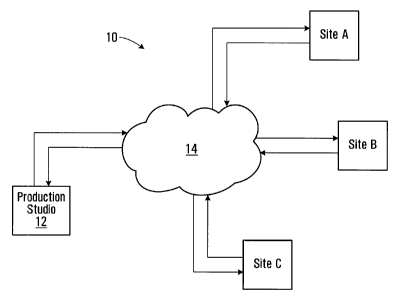
As shown in Figure 1, the system 10 is implemented over a fairly wide
geographical area and includes an infrastructure having components in multiple
io venues that can be at a significant distance from one another. In the
example
shown, the system 10 involves three venues, namely venue A, venue B and
venue C. Each venue can be a stadium in which a football game can be
played. Those stadiums would normally be located in different cities that can
be many miles apart. The system 10 also includes a production studio 12 that
is remote from venue A, venue B and venue C. In a specific and non-limiting
example, the production studio 12 is located in yet another city and may even
be located in a country that is different from the country in which sites A, B
or C
are located.
The production studio 12 and sites A, B and C are all linked via a data
connection shown as a network 14. The network 14 allows data to be sent from
any one of the sites A, B or C to the production studio 12 and also allows
data
to be sent from the production studio 12 to any one of the sites A, B or C.
The
type of network 14 used to perform the data transport function from the sites
A,
B and C to and from the production studio 12 is not critical as long as it can
meet sufficient performance requirements. Networks based on optical fiber
technology that provide a high bandwidth, low latency and high speed data
transmission have been found satisfactory. Note that the network does not
need to be strictly landline based buy may include wireless segments.
Figure 2 illustrates in greater detail the components of the system
infrastructure at venue A. The system 10 includes a series of inputs 11 that
capture audio, video and data content associated with the local live sporting
CA 02569967 2006-12-04
9
event, such as for example the football game held at venue A. The system 10
also includes an output 15 that returns to venue A a digital signal having a
'video/audio/data content that is then locally broadcast to individual
portable
devices 16, each device 16 being intended to be used by a single attendee or
s:spectator watching the live sporting event. In a typical application, a
significant
number of devices 16 can be accommodated. For instance, in a football game
-that may attract several tens of thousands of attendees, the system
infrastructure at a single venue should be designed to potentially support an
equal number of portable devices 16.
The transmitter 18 communicates with the individual handheld electronic
devices 16 in a wireless manner. In the example that is being shown in the
drawings, the communication is a Radio Frequency (RF) communication. This
RF transmission is unidirectional. In other words, the information stream is
from
is 1the transmitter 18 to each electronic device 16. This is accomplished in
the
Ibroadcast mode wherein each electronic device 16 receives the same
information from the transmitter 18. In the unidirectional RF transmission,
the
handheld electronic devices 16 are unable to transmit information back to the
1transmitter 18 over the wireless RF communication link.
In a non-limiting example of implementation the wireless RF transmission
is performed locally of the venue. "Locally of the venue" means that the
antenna generating the wireless RF transmission originates either at the venue
or outside the venue but generally close to the venue. The signal power level
is
also controlled such that handheld electronic receivers 16 can adequately
receive the wireless RF transmission at the venue, but at significant
distances
iFrom the venue the signal weakens and may no longer permit a quality
reception. By "significant" distance is meant a distance in terms of kilometer
range.
It should be understood that the handheld electronic devices 16 can be
capable of unidirectional wireless communication, as described above, or
alternatively, they can be capable of bi-directional wireless communication.
In
CA 02569967 2006-12-04
the case of unidirectional wireless communication, the handheld electronic
devices 16 are only able to receive wireless information. In other words, they
are not able to transmit information back to the transmitter 18, or to another
receiver/transmitter, over a wireless communication link. It should be
5 appreciated that although the handheld electronic devices 16 may only be
capable of unidirectional wireless communication, they may be operative to
transmit and receive information over a wireline link, such as via a USB
connection port, for example.
10 In the case of bi-directional wireless communication, each handheld
electronic device 16 is able to receive information over a wireless
communication link, and is also able to transmit information over a wireless
communication link. In this case the electronic device 16 is provided with an
RF
transceiver (not shown in the drawings) that can handle the receive and
transmit functions. The transmitted information may be sent to an entity of
the
system 10 (not shown), or to an entity of an external network that is
independent of the system 10. The handheld electronic devices 16 may be
operable to transmit information over a wireless RF communication link, such
as
over a cellular link. In the case of a cellular link, the handheld electronic
devices 16 would dial a phone number and then transmit information over the
cellular phone link.
The bi-directional communication feature may be implemented to provide
identical or similar bandwidths over the receive and transmit links. However,
in
rnost cases, this is not necessary since the amount of information that needs
to
be sent from the handheld electronic device 16 is generally different from the
amount of information that it needs to receive. Typically, the handheld
electronic device 16 needs to send far less information that it receives. The
implementation using the cellular network is an example that would provide a
sufficient bandwidth over the transmit link. By "cellular" network is meant a
network that uses a series of cells having a limited geographical extent
within
which communication services are available. In one possible form of
implementation, such cells can be arranged to provide a hand-off to moving
CA 02569967 2006-12-04
11
handheld electronic devices 16, such that as a handheld electronic device 16
moving outside a cell and entering a new cell, the communication services are
seamlessly transferred from one cell infrastructure to another cell
infrastructure.
'The "cellular" network terminology encompasses both communication
nfrastructures using licensed bandwidth, such as typical cellular telephones
Ibased on Code Division Multiple Access (CDMA), Time Division Multiple
Access (TDMA), Groupe Station Mobile (GSM), or other technologies, and
communication infrastructures using unlicensed bandwidth, such as Wireless
IFidelity (WiFi) that is used commonly to provide wireless access to computer
io inetworks. Another possible example of a "cellular" technology using
unlicensed
bandwidth is the so called "Bluetooth" protocol that provides very short range
wireless communication capabilities.
The cellular network allows the handheld electronic device 16 to transmit
information over a relatively limited bandwidth, however, in most cases the
amount of information that needs to be sent is low such the available
bandwidth
should suffice. On the other hand, the receive link has a higher bandwidth in
order to accommodate the multiple video streams and other data that is to be
sent to the handheld electronic device 16. Also the cellular link allows the
Ihandheld electronic devices 16 to transmit information independently from one
another.
The input 11 receives signals that convey video/audio/data content
originating form various sources. In the example shown in Figure 1, a number
of content sources are shown, which for the purposes of the present
application
will be described in the context of a football game. There are multiple video
fieeds 31 that originate from cameras along the football field. The cameras
capture images of the live football game and output the video information
making up the respective video feeds 31. Note that one of the video feeds 31
Ileads to an encoder 33. This encoder 33 can be provided to encode the native
video format in any suitable format that may be necessary to facilitate the
transport of the video signal or its processing at the production studio 12.
The
encoder 33 is optional and can be omitted if the encoding of the video feed is
CA 02569967 2006-12-04
12
not required or can be done elsewhere in the system 10.
Multiple audio feeds 32 are also provided, where each audio feed 32 is
associated with a video feed 31. An audio feed 32 conveys audio information
such as the noise picked up by a microphone at a location at which the
associated camera is placed, or an audio commentary. Such an audio
commentary can be the speech picked up by a microphone from a
commentator or any individual that appears in one or more of the video feeds
31. Note that the audio feeds 32 are shown separate from the video feeds 31
io for clarity only. In many practical applications the video feed 31 and the
associated audio feed 32 will be carried over a common physical conductor.
Independent audio feeds 35 are also provided that convey independent
audio content which is not associated with any particular video feed 31. For
instance those independent audio feeds 35 may be radio conversations
between members of a football team or a radio commentary by a reporter over
a radio channel. Such audio conversations can be picked up by one or more
radio receivers (not shown) each tuned to a particular frequency.
The audio and video content is typically supplied by the authority
managing the live sporting event. For example, in the case of a football game,
the video and audio data might by supplied by the National Football League.
(NFL). In a further non-limiting example, the independent audio feeds that
contain audio commentary may be supplied by the commentator's affiliated
television network, such as TSN, for example.
The input 11 also receives a real time data content 37. The real time
data content 37 conveys information relating to the action in the field. For
example, the real time data content in the context of a football game can be:
= the present score;
= time remaining to play;
= penalties
= number of time outs left;
CA 02569967 2006-12-04
13
= current down;
= number of downs left;
= yardage to go, among others.
The real time data content 37 is typically also supplied by the authority
imanaging the live sporting event.
The video content, the audio content and the data content are physically
nput into a patch panel 50 that is the entry point in the network 14. The
io inetwork 14 transports this video/audio/data content to the remote
production
studio 12 where it will be edited.
The infrastructure of the system 10 for sites B and C functions in the
,same way as described above. Specifically, each of the sites B and C
produces audio/video/data content that is transported to the production studio
12 for editing. In a specific example of implementation each venue is hosting
a
lfootball game between two teams and the games are concurrent at least in
part.
ln the context of two sites, say sites A and B, games concurrent at least in
part
means that each venue is hosting a football game and both games overlap time
wise. In other words, when one of the games begins, the other game starts
concurrently or has already started. With games concurrent at least in part,
game action occurs simultaneously at different sites. In a specific and non-
limiting example of implementation, the games at the venues serviced by the
system 10 (sites A, B and C) start simultaneously. The games are unlikely to
end at the same time since the duration of an individual game can vary but for
the most of the duration of the game, three different game actions occur
simultaneously at different sites remote from one another. In this example the
game that is held at each venue is the same type of game, namely a football
game. The invention can also be used in applications where different types of
cJames occur at the sites A, B and C and those games are concurrent at least
in
part. For example, venue A may be hosting a football game, while sites B and
C. are hosting baseball games. The game at venue A starts at 7:00 PM while
1:he games at sites B and C start at 7:30 PM. Thus, from 7:30 PM three
CA 02569967 2006-12-04
14
different game actions are in occurrence, there being one football game and
1:wo baseball games.
Figure 3 is a more detailed block diagram of the production studio 12.
The production studio 12 connects to the network 14 via an input 52 and
receives via that input 52 the video/audio/data content originating from the
sites
A, B and C. For clarity the input 52 is depicted as three arrows, each
symbolizing collectively the video/audio/data content originating at a
different
site. The video/audio/data content from each venue is received at a content
io production station 54. The content production station 54 is an optional
component and it provides a facility where a technician can format or edit the
raw content to make it more suitable for presentation to the audience. The
content production station 54 includes a console that allows the technician to
conduct the necessary content editing operations.
Figure 4 is a more detailed block diagram of the content production
station 54. The content production station 54 has several content production
consoles each associated with a site. In the example shown, there are three
content production console units 56, 58 and 60 associated with the sites A, B
and C, respectively. Each content production console unit 56, 58 and 60 can
edit the video/audio/data content originating at a given site. The editing
operation includes selecting among the video/audio/data information that
arrives at input 54, the one that will be eventually delivered to the
spectators.
For example, the video/audio/data content from a given venue may contain
several video feeds. The technician at the content production console unit 56,
58, 60 can chose the video feed that will be delivered among the video feeds
available. The same operation can be performed on audio and data content.
Also, note that the content production station 54 can edit the
video/audio/data
content, if desired.
The content production console units 56, 58 and 60 can also mix the
content. The mixing function is accomplished by linking the content production
console units 56, 58 and 60 to one another via data interconnects 62, 64 and
CA 02569967 2006-12-04
66. The data interconnects 62, 64 and 66 allow content that originates from
one venue A, B or C to be delivered to the content production console unit 56,
58, 60 associated with another site. The way in which the content mixing
operation will be performed is under the direct control of the operator of the
5 content production station 54.
Each content production console unit 56, 58, 60 has an output 68, 70
and 72 that releases an edited and mixed audio/video/data content. Examples
of mixing operations include:
1. Venue A, Venue B and Venue C host football type games that are
concurrent at least in part.
The mixing operation includes directing at least one video feed 31 and
an associated audio feed 32 originating at venue A into the content of
each of the sites B and C. The same operation is performed with the
content of sites B and C such that the content associated with each
venue will also hold a video feed and an associated audio feed from
each other site. For instance, assume that the video/audio/data content
that is input into the content production console unit 56 includes a single
video feed and a single associated audio feed associated with venue A.
Similar operations are performed by the content production console units
58, 60 on the video/audio/data content from sites B and C, respectively.
After the mixing operation, the video/audio/data content released by the
content production console unit 56 at output 68 will contain three video
feeds and three associated audio feeds, where each video feed and the
associated audio feed originate from a different site. The same
operation happens at the content production consoles 58, 60 that output
at 70 and 72, respectively video feeds and associated audio feeds
originating from different sites.
In a possible variant, In addition to mixing video and associated audio,
independent audio content can also be mixed. The process is effected
generally as described earlier. Independent audio content originating
CA 02569967 2006-12-04
16
from anyone of the sites A, B or C is directed via anyone of the data
interconnects 62, 64, 66 into the content output 68, 70, 72 of another
venue A, B, C. In a specific example the independent audio content
originating from each venue A, B, C is injected in the content output 68,
70, 72 associated with every other site. In this fashion, the
video/audio/data content in every output 68, 70, 72 contains independent
audio content from every venue A, B, C.
Yet, in another variant, in addition to mixing video and audio (associated
and/or independent), data can also be mixed, generally in the manner as
described earlier.
It will be appreciated that the number of video feeds, associated audio
feeds, independent audio feeds and data elements that are being mixed
is can vary without departing from the spirit of the invention. Depending on
the number of video feeds, associated audio feeds, independent audio
feeds and data elements present in the video/audio/data content
originating at a certain venue one, two or more of those components can
be mixed with content from other sites.
2. Venue A and Venue B host football type games that are concurrent
at least in part and Venue C hosts a motor sports event.
In this form of implementation the mixing of video/audio/data content
occurs between sites A and B. Venue C operates independently. In
other words, the data interconnects 64 and 66 are not used. This
example assumes that there is no interest for spectators at sites A and B
to obtain content from venue C hosting a different event. In the case
interest exists, the operation can be effected in the same way as
example 1.
3. International competitions such as the Olympic Games or the World
Soccer Cup.
This form of implementation would be similar to 1 above. Consider for
CA 02569967 2006-12-04
17
example the Olympic Games where several events may occur and those
may be concurrent at least in part. The events are different from one
another, for example one may be a swimming competition, one may be
athletics competition and one is a boxing competition. All those events
are held in different venues. The video feeds, associated audio feeds,
independent audio feeds and the data elements are received from each
venue and send to the content production station 54 where they are
mixed as required. After the mixing operation, the video/audio/data
content released by the content production console unit 56 is directed to
lo the individual venues as discussed above.
An implementation during the World Soccer Cup would be essentially the
same as the Olympic Games, the exception being that the same type of
sport is being played, namely soccer games, at the various venues.
Referring back to Figures 3 and 4, the content at outputs 68, 70, 72 that
is released from the content production station 54 is directed to a head end
station 80. The head end station 80 is a modular entity having individual
components associated with respective content production console units 56, 58
2o and 60. One of the components of the head end station 80 is shown in
greater
detail in Figure 5. That component, referred to as "head end station unit" 82
is
associated with the content production console unit 56 and it processes the
video/audio/data content on output 68. The two other head end station units
associated with the content production console units 58 and 60, respectively,
are not shown in the drawings for clarity. Those head-end station units
operate
in the same way as head end station unit 82.
The head end station unit 82 receives seven different inputs. Those
inputs are broadly described below:
1. The first input, designated by reference numeral 100 includes the
multiple edited video feeds that are present in the output 68 from the
content production console unit 56. The video feeds include one or more
CA 02569967 2006-12-04
18
video feed originating from venue A and one or more video feeds
originating from venue B and/or from venue C depending on the mixing
operation performed by the content production station 54. In a specific
example of implementation the video feeds 100 are transmitted
according to a Serial Digital Interface (SDI) format.
2. The second input 200 includes the multiple edited audio feeds that
are associated with respective video feeds in the input 100. Those audio
feeds include one or more audio feeds originating from venue A and one
ore more audio feeds originating from venue B and/or from venue C
depending on the mixing operation performed by the content production
station 54. The audio feeds in the input 200 can be transmitted in any
suitable format.
3. The third input 300 includes the multiple independent audio feeds.
Those audio feeds include one or more audio feeds originating from
venue A and one or more audio feeds originating from venue B and/or
from venue C depending on the mixing operation performed by the
content production station 54. The audio feeds in the input 300 can be
transmitted in any suitable format.
4. The fourth input 400 includes the real time data content that is
transmitted digitally to the head end station unit 82. This content
includes content originating from venue A and also content originating
from venue B or from venue C depending on the mixing operation
performed by the content production station 54. For example, the real
time data content in the context of a football game can be:
- the present score;
- time remaining to play;
- penalties
- number of time outs left;
- current down;
- number of downs left;
CA 02569967 2006-12-04
19
- yardage to go, among others.
In another example, the real-time data content can also convey
physiological information associated with anyone of the participants.
Again in the context of a football game, the physiological information can
include the heart rate of a player or his body temperature, among others.
The real time data content is usually available from the authority
sanctioning the live sporting event. In the case of the physiological
information, one possible implementation would require providing one or
more of the participants with the necessary sensors that measure the
heart rate, body temperature, etc and convey the collected information to
the head end station unit 82. It is not deemed necessary to describe in
detail how the physiological information is collected and delivered to the
head end station unit 82, since this would be known to a person skilled in
is the art.
5. The fifth input 500 includes authentication data received from an
authentication database 502. The authentication data 500 is digitally
transmifted to the head end station unit 82. Note that for simplicity inputs
500, 600 and 700 are shown by a single arrow. In practice the data in
those inputs can be conveyed over separate or common conductors.
6. The sixth input 600 includes ancillary content that is output from
an ancillary information database 602. The ancillary content 600 can be
in the form of video, audio or data, such as text for display to the
spectator. Examples of ancillary content includes:
a) Advertisement content. The advertisement content can be
delivered in the form of video, audio or a combination of video
and audio. Examples include short movies, still images, or
portions of still images appearing as overlays on other video
content appearing on the user's screen. The advertisement
content can be delivered in a wide variety of ways. Examples
CA 02569967 2006-12-04
include:
i) A first possibility is to broadcast the advertisement content
such that it is played at each handheld electronic device
16. In this fashion each spectator is exposed to the same
5 content. Ads can be channeled to the handheld electronic
devices 16 over individual video/audio streams such that
the spectator can select when to view the ads or not view
the ads. For example, the handheld electronic device 16
can be programmed in a way to allow the spectator to
io access a special add channel that continuously runs the
ads content. Alternatively, ads can be inserted in the
video/audio streams that convey the event-related content.
For example during idle times, ads can be run. Such ads
can be in the form of short movies that are played on the
15 handheld electronic device 16 for a predetermined time
period, such as 30 seconds. Another possibility is to
present the ads as banners, logos or in a "ticker" type
fashion that appears on certain areas of the handheld
electronic device's screen.
20 ii) A second possibility is to deliver the ad content according
to spectator profiles. The ads are organized into blocks,
where each block corresponds to a spectator profile.
Spectator profiles can be defined in various ways, such as
age groups, gender, level of revenue, area of interest or
combinations of the above, among many others. For
instance, with profiles that are distinguished from one
another on the basis of gender, ads that are intended to
attract the interest of males can be directed in one profile
while ads that are more likely to be of interest to females
can be placed in the other profile. In the case of profiles
that are distinguished on the basis of revenue level, ads on
products or services would be placed in profiles according
to the cost of the product or service; more expensive
CA 02569967 2006-12-04
21
products or services would be placed in profiles associated
with higher revenue levels.
b) Venue or event related contextual content. In the case of
football games, the contextual content may include information
about the sport such as, the history of the sport, the list of the
teams involved in the championship, the information about each
team, statistics about each team or about individual team
members, instructions on where to find certain facilities at the
venue such as washrooms, vending machines or stands, among
many others.
c) News. The news content may include "breaking" news bulletins,
weather information, and economic information such as stock
exchange averages or indices, among others.
is d) Environmental conditions. In the case of certain live sporting
events, environmental conditions can greatly affect the way the
game is played. As such, information relating to environmental
conditions such as current temperature, wind speed and
direction, humidity, weather forecast, etc...might be of interest to
a spectator.
e) Shopping Information. A shopping service may be provided to
a spectator in order to enable the spectator to purchase
products and paraphernalia related to the live sporting event,
such as T-shirts, caps, related sporting equipment and
autographed items from the players or participants. The
shopping information may be displayed in the form of an
electronic catalogue of purchasable items that lists the products
and paraphernalia that are for sale. The shopping catalogue
may also include products from the sponsors of the sporting
event.
In a non-limiting example of implementation, the advertisement
information described above in paragraph a) may be tied into the
CA 02569967 2006-12-04
22
shopping service. For example, during the sporting event, the
advertisement information may indicate to a spectator that products from
the event's sponsors are available for purchase in the on-line shopping
catalogue. In addition, when an exciting event occurs in the live sporting
event, such as the winner of the football game is determined, the
advertisement information can indicate to a spectator that T-shirts and
other items associated with the winner of the event can be bought via the
on-line shopping catalogue.
In order to purchase products from the on-line shopping catalogue, a
spectator would add selected items to a virtual "shopping cart" and then
"checkout".
In the case where the handheld electronic device 16 is only capable of
is unidirectional wireless communication, the spectator would then have to
physically connect the handheld electronic device 16 (via a USB port, for
example) to a purchasing terminal located at the sporting event, or to
their PC when they arrive home. The purchasing information would then
be downloaded from the handheld electronic device 16 to the terminal or
PC, which can then transmit the information to the appropriate entity.
Alternatively, in the case where the handheld electronic device 16 is
capable of bi-directional wireless communication, as described above,
the purchasing information can be sent immediately over a wirelessly
communication link, to an appropriate receiver/transmitter. The
appropriate receiver/transmitter may be part of the system 10, or may be
part of an external network.
The ancillary content 600 can be obtained from a wide variety of
sources. The advertisement, shopping, venue or event related
information can be recorded on any suitable medium and injected in the
video/audio content at the head end station 80. Specifically, the
advertisement, shopping, venue or event related information could be
CA 02569967 2006-12-04
23
digitally stored on a database 602. The output of the database 602 leads
to the head end station 80 such that the video/audio content in the
database 602 can be injected in the video/audio content that is being
broadcast to the handheld electronic devices 16. The Internet is another
source of ancillary content. Specifically, the news service can be
delivered from the internet and injected in the video/audio content that is
being broadcast to the handheld electronic devices 16.
7. Finally, the seventh input 700 includes service data. The service
data resides in a database 701. This database can also connect to the
Internet to obtain updates or program releases that may not be available
prior the beginning of the event being serviced by the system 10.
Examples of service data include:
a) Data for setting the software running each handheld electronic
device 16. (For the purpose of this specification "setting" means
either altering the software that may already be in the electronic
device 16 or loading new software that was not present in the
electronic device 16). For example, the service data may be
used to set the user interface of the each handheld electronic
device 16. In a non-limiting example of implementation the user
interface is a Graphical User Interface (GUI). The user interface
setting can be effected in order to customize the handheld
electronic devices 16 for the local event. For instance, data can
be sent to the handheld electronic device 16 that forms a menu
on the handheld electronic device 16. The menu is such as to
provide the spectator with a list of options. Another GUI
component that can be customized or tailored for a particular
event or venue is the graphical GUI information, such as
background images on which other GUI elements can be
displayed to the spectator. The service data may convey the
Graphical User Interface (GUI) in multiple different languages so
as to provide multiple language support to the users of the
CA 02569967 2006-12-04
24
handheld electronic devices 16. In this manner, users of the
handheld electronic devices 16 can select their language of
preference. The choice of language may be presented to the
spectators in an initial start-up screen that is displayed upon
powering up the handheld electronic device 16. Specifically, the
following components of the user interface can be set via the
service data:
i) Background image information;
As discussed above this is the graphical information
associated with the user interface.
ii) Menu structure and look;
This refers to the option items of the menu, in particular the
options hierarchy, the options themselves (what are the
options available to the spectator from which the spectator
can select an action), the graphical elements of the menu,
such as the disposition of the option items on the display,
color and shape of the option items, etc.
iii) Soft keys layout and look (soft keys will be discussed later);
The aesthetical components of soft keys, such as their
location on the screen, their shape, color, etc.
iv) Soft keys assignments;
The functions assigned to the respective soft keys
v) Layout of icons on the display;
The appearance and disposition of the icons on the display
screen
vi) Navigation mechanisms
The type of navigation mechanisms to which the user
interface responds, such as up, down, left and right arrows,
pointing devices, voice recognition, etc.
b) Cartographic data that can be used by the handheld electronic
device 16 to display a map of the venue or a portion thereof.
The cartographic data can be used in a standalone manner to
CA 02569967 2006-12-04
show on the display of the handheld electronic device 16 a map
of the venue that can be zoomed in or out to the desired degree
of detail or panned to show different areas of the map.
Alternatively, the cartographic data can be used in conjunction
5 with a coordinates receiver, such as a Global Positioning
System (GPS) receiver that can generate the coordinates of the
location of the handheld electronic device 16. The coordinates
can then be used to show on the display the map of the venue
and point the location of the handheld electronic device 16. The
10 cartographic data can also include specific locations of interest
such as washrooms, vending stands, parking, etc. When the
cartographic data is intended to work with location information
generated by a GPS receiver or any other suitable device
capable of producing location information it will typically be
15 georeferenced. For maps that are not intended to work with
devices producing location information, such georeferencing is
not required since the map is processed simply as an image to
be viewed by the spectator.
The head end station unit 82 organizes the data from the various inputs
into a structured information stream for broadcasting to the individual
handheld
electronic devices 16. The head end station unit 82 has a video processor 102,
an audio processor 104, a control entity 106 and a multiplexer 108. The
control
entity 106 includes a computing platform running a program to carry out
various
tasks. While not shown in the drawings, the computing platform includes a
processor, memory to hold the program code and data that is being processed
by the processor. In addition, the computing platform has a Graphical User
Ilnterface (GUI) 110 that provides a technician with the ability to send
commands to the control entity 106 or to receive information therefrom. The
GUI 110 can take various forms without departing from the spirit of the
invention. For instance, the GUI 110 can include a display on which
information
is shown to the technician and a keyboard and mouse combination for data and
CA 02569967 2006-12-04
26
commands entry.
The control entity 106 receives the various forms of information and will
direct them to the appropriate encoders for processing. Specifically, all the
video feeds that are received at the head end station unit 82 are handled by
the
video processor 102 that will convert the SDI format into Moving Picture
Experts
Group (MPEG) - 4 format. Each video stream is compressed to provide at the
handheld electronic device 16 a moving image at 30 Frames per second (fps),
'16 bit colors at a 320X240 pixels resolution. The resulting bit rate is 384
io Kbits/sec. Since the video processor 102 needs to handle multiple video
feeds
simultaneously it is designed in order to be able to process those feeds in
parallel. The preferred form of implementation uses a plurality of encoder
stations, each being assigned a video feed. The encoder stations can be based
on dedicated video processing chips or purely on software, or a combination of
both. Alternatively, the video processor 102 can use a single processing
rnodule with buffering capabilities to sequentially handle blocks of data from
different video feeds. With an adequate size buffer and a processing module
i:hat is fast enough, all the video feeds can be encoded without causing loss
of
data.
Note that since MPEG-4 encoding also handles audio, the audio feeds
that are associated with the respective video feeds are also directed to the
video processor 102. The output of the video processor 102 is thus MPEG-4
encoded video channels where each channel has a video stream portion and
an audio stream portion.
The independent audio feeds 35 that constitute the third input 300 are
directed to an audio processor 104 that will encode them into a Moving
Pictures
Experts Group Audio layer 3 (MP3) format. Since the MP3 encoded audio
streams convey voice information they can be compressed into an 8Kbits/sec
data rate while maintaining adequate quality. As in the case with the video
processor 102, the audio processor 104 uses a series of audio encoding
stations, each dedicated to a given audio feed. Alternatively, the audio
CA 02569967 2006-12-04
27
processor 104 can use a single sufficiently fast encoding module having
buffering capabilities to sequentially handle data blocks from all the audio
feeds.
The control entity 106 handles the processing of the fourth, fifth, sixth
and seventh inputs, namely the real time data, the authentication data, the
ancillary content and the service data. The purpose of the processing is to
packetize the data such that it can be transmitted to the individual handheld
electronic devices 16.
The outputs of the control entity 106 and the video and the audio
processors 102, and 104, are passed to a multiplexer 108 that combines the
data into one common data flow. The data flow is then directed to an output
112. The data flow at the output 112 is organized in the form of packets. In a
specific and non-limiting example of implementation, three types of packets
are
being sent. The first type includes the video information. In essence, the
MPEG-4 information is packetized and transmitted. The video information
packet includes a header that contains the relevant data allowing a handheld
electronic device 16 to appropriately decode it and process it.
Advantageously,
error detection and correction data is also included in the header for a more
reliable transmission. The second type of packet includes the independent
audio information. The third type of packet includes the remainder of the
payload, such as the ancillary information and the real and service type data.
As in the case of the first type of packet, the second and third types of
packets
include identification data in the header to inform the handheld electronic
device
-16 what type of content the packet holds such that the content can be
adequately processed.
The table below provides an example of data at the output 112 and the
respective bit rate.
Required Number of Aggregated
Description unit bit feeds bit rate
rate
Live video feeds 31, 320 x 384Kbits/s 10 3,84 Mbits/s
CA 02569967 2006-12-04
28
240 pixels, 16 bit colors, ec
30FsMe 4)
Audio feeds 32 28.8Kbits/s 10 288Kbits/sec.
(synchronized with video ec.
feeds-MP3
Independent voice grade 8Kbits/sec. 48 384 Kbits/sec.
compressed audio feeds
35 (MP3)
Real time data 37 - 6,000 480Kbits/s 1 480 Kbits/sec.
ASCII Characters (or ec.
equivalent data payload) of
high priority refresh
Ancillary content and 1 Mbits/s 1 1 Mbits/sec.
service data, (several
priority refresh levels)
Authentication data 256 bits/30 50,000 425Kbits/sec.
sec.
Spare =1 Mbits/sec.
Overall payload 7.5 Mbits
As mentioned previously, the head end station 80 includes a number of
head end station units 82 identical to the number of sites that are being
serviced by the system 10. In the present case, there are three head end
station units 82, associated with the sites A, B and C, respectively. Each
head
end station unit 82 issues a data flow at its output 112 that is directed to
the
r-espective site. Figure 3 illustrates the collective output of the head end
station
80. For clarity, the output is shown as three separate data streams,
designated
as 112A, 112B and 112C that are directed to sites A, B and C, respectively.
The data streams 11 2A, 11 2B and 11 2C may be identical but for most
applications they will carry different content. The content may differ in
terms of
video streams, associated audio streams and independent audio streams,
which is determined largely by the mixing operation performed at the content
production station 54. If every video, associated audio and independent audio
stream from a venue is distributed to every other site, ultimately the video,
associated audio and independent audio streams in the data streams 112A,
'112B and 112C will be the same. When a more limited mixing is performed
then the data streams 112A, 112B and 112C will be different.
CA 02569967 2006-12-04
29
The most likely difference, however, between the data streams 112A,
'112B and 112C is at the level of the ancillary content. Since in most
applications the ancillary content is likely to be venue specific, this
distinction
will be reflected in the data streams 112A, 112B and 112C. More specifically:
1. Advertisement content. The advertisement content may or may not be
different. One possibility is to deliver the same advertisement content to
two or more sites that are serviced by the system 10. Another possibility
is to tailor the advertisement for every venue or group of sites. In this
io form of implementation, the data streams 112A, 112B and 112C will
carry different advertisement content.
2. Venue or event related contextual information. The venue or event
related contextual information is likely to be different from one data flow
11 2A, 11 2B and 11 2C to another since it is venue specific. One instance
where the venue or event related contextual information is the same is
when each data flow 112A, 112B and 112C carries venue or event
related contextual information for every site, leaving the spectator to
make a selection on the handheld electronic device 16.
3. News. The news content may be different or identical depending on the
type of news that is delivered. For "national" news that are relevant for
each site, the news content in the data streams 11 2A, 11 2B and 11 2C is
likely to be the same. However, if the news are "local" and specific to
each venue then they are likely to be different from one data flow 11 2A,
112B and 112C to another. Again, the possibility exists to carry in each
data flow 112A, 112B and 112C separate local news streams, where
each local news stream is relevant for a different site, leaving the
spectator to select what is of interest.
4. Environmental conditions. The environmental conditions are likely to be
different in each data flow 112A, 112B or 112C since the environmental
conditions are venue specific. Here again the possibility exists to carry in
each data flow 11 2A, 11 2B and 11 2C separate environmental conditions
streams, where each environmental conditions stream is relevant for a
different site, leaving the spectator to select what is of interest.
CA 02569967 2006-12-04
5. Shopping information. The shopping content may be the same for each
data flow 112A, 112B or 112C but it is likely to be different. In most
applications the shipping information content will be venue specific, such
as for example relating to paraphernalia about the teams that play at that
5 site. As indicated earlier the possibility exists to carry in each data flow
112A, 112B and 112C separate shipping information streams, where
each shipping information stream is relevant for a different site, leaving
the spectator to select what is of interest.
10 Another likely difference between the data streams 112A, 112B and
1 12C is at the level of the service data. Since the service data is likely to
be at
least to some extent venue specific, it will be different from one data flow
11 2A,
112B and 11 2C to another. Differences could be at the following levels:
15 1. The data for setting the user interface of the handheld electronic
devices
16. Since the user interface is likely to be venue specific, then the data
setting the user interface in each data flow 11 2A, 11 2B and 11 2C is likely
to be different. For instance, the user interface setting data determines a
menu of choices that is related to the local teams playing the game. The
20 menu of choices can include a list of players or teams on which detailed
information can be accessed by the spectator. Since different players or
teams participate in the game at each site, the menu of choices for that
site's handheld electronic devices 16 is different from the menu of
choices for handheld electronic devices 16 of another site. Similarly, the
25 background graphical information for the GUI may be venue specific.
More generally, the following components of the user interface can be
customized:
a. Background image information;
b. Menu structure and look;
30 c. Soft keys layout and look (soft keys will be discussed later);
d. Soft keys assignments;
e. Layout of icons on the display;
f. Navigation mechanisms.
CA 02569967 2006-12-04
31
As with the examples discussed earlier, it is also possible to convey in
the data flows 112A, 112B and 112C user interface setting data suitable
for each site, and providing the handheld electronic device 16 with
functionality to select and make use of the relevant data and disregard
the rest.
2. Cartographic data. The cartographic data is likely to be different among
the data flows 11 2A, 11 2B and 11 2C since it is venue specific. Again the
possibility exists to send in each data flow 112A, 112B and 112C
cartographic data for each site, leaving the user of the handheld
electronic device 16 to make the relevant selection.
Yet another possible difference between the data flows 112A, 112B and
112C is the authentication data. Depending on the specific authentication
scheme used, the authentication data in each data flow 112A, 112B and 112C
could be different and specific to the population of handheld electronic
devices
16 at the venue A, B or C associated with that data flow 11 2A, 11 2B and
112C.
Alternatively, the authentication data can be the same in each data flow 112A,
112B and 112C.
The databases 502, 602 and 701 are designed to provide the relevant,
authentication data, ancillary data and service data to each head end station
unit 82. For instance, there may be databases 502, 602 and 701 that are
associated with a specific head end station unit 82, when the data they
provide
is venue specific. Although the drawings show architecture where the
databases 502, 602 and 701 are shared among the head end station units 82,
i:his is only for the purpose of simplified illustration. The present
invention
E:ncompasses both options, namely a shared set of databases 502, 602 and
701 and multiple database sets 502, 602 and 701 that are venue specific.
Referring back to Figure 3, the head end station 80 is shown as
CA 02569967 2006-12-04
32
outputting the data flows 112A, 11 2B and 11 2C that are in turn input in the
data
network 14. The data network delivers those data flows 112A, 112B and 112C
to the sites A, B and C, respectively. With reference to Figure 2, the data
flow
112A is delivered at output 15, supplied to a modulator 17 and then to
transmitter 18. The modulator 17 and the transmitter 18 produce a wireless RF
broadcast that uses a 6 MHz contiguous channel bandwidth, centered at
;2.5GHz to broadcast the digital data flow 112A to the handheld electronic
devices 16 at venue A. Alternatively, the transmission may also be made in the
IJltra High Frequency (UHF) range, specifically in the sub range of 470 MHz to
io 806 MHz. A 6 MHz contiguous bandwidth (equivalent to one regular TV
channel) is sufficient to transmit the exemplary payload indicated earlier.
The
digital data flows 112B and 112C are broadcast in the same manner in the
respective sites, as described in connection with venue A.
Figure 6 shows a perspective view of the handheld electronic device 16
that can be used in any one of the sites A, B and C to pick up the local
wireless
RF broadcast. The handheld electronic device 16 is portable and designed to
fit comfortably in the spectator's hand. It includes a keyboard 800 with the
necessary keys to control the operation of the handheld electronic device 16.
Above the keyboard 800 is provided a display section 802 in which is placed a
display screen.
Figure 7 is a block diagram of the handheld electronic device 16. The
handheld electronic device 16 is a computer-based apparatus that receives the
information sent by the transmitter 18. The video information is displayed on
the display screen 802 and the audio information is played via suitable
speaker/headphones 724. The spectator can control the selection of the video
channels as well as to perform other operations. By video channel at the
handheld electronic device 16, it is meant a combination video stream and an
associated audio stream.
As seen in Figure 7, the handheld electronic device 16 has a processor
700 that executes software for controlling the various functions of the
handheld
1 1, I i i I i i
CA 02569967 2006-12-04
33
electronic device 16. Generally, the software has four main layers, namely:
= The configuration layer
The configuration layer allows the user or the manufacturer to set
characteristics of the handheld electronic device 16, such as enable or
disable options, language, time, passwords, etc.
= The GUI layer
In the example described in this specification the GUI includes a graphical
and navigation layer that allows the spectator to access specific functions
of the handheld electronic device 16. The GUI would typically present to
the spectator on the screen options, such as menus that the spectator can
navigate to access the feature that is desired. As indicated earlier, the
service data portion of the data flow 11 2A, 11 2B and 11 2C broadcasted by
the transmitter 18 contains information that determines how the graphical
and navigation layer will appear to the spectator. The following are
examples of the types of GUI components the service data portion can set
on the handheld electronic device 16:
i. Background image - an image that appears on the screen and
on which are overlaid other types of information such as menu
choices. For instance the background can have a visual theme
associated with the event or venue A, B and C. The background
image can change for different events or sites;
ii. Menu structure - define the options hierarchy that is available to
the spectator. For example, for a certain event, 10 video
channels or other options are available but for other events,
fewer or more channels or options are possible.
iii. Menu look and details - the visual appearance and prompts
associated with the various menu choices. For instance, the
different video channels may have names or identifiers
CA 02569967 2006-12-04
34
associated therewith, such as the video channel from the left
side of the football field, the video channel from the right side of
the football field, etc. Also the different menu options can have
different colors, different shapes or dispositions on the display.
iv. Soft keys assignment - Referring briefly to Figure 6, the
handheld electronic device is provided with Function keys 810
(Fl, F2, F3 and F4). The user interface may assign different
functions to each physical key Fl, F2, F3 or F4. In a specific and
non-limiting example of implementation, the current assignment
of a key is displayed on the display 802, immediately above the
associated physical key (Fl, F2, F3 or F4).
v. Soft keys layout and look - The aesthetical components of soft
keys, such as their location on the screen, their shape, color, etc.
vi. Layout of icons on the display - The appearance and disposition
of the icons on the display screen.
vii. Navigation mechanisms - The type of navigation mechanisms to
which the user interface responds, such as up, down, left and
right arrows, pointing devices, voice recognition, etc.
In a non-limiting example of implementation, the data for setting the
GUI in the handheld electronic device 16 is sent during a window of
operation that precedes the beginning of the wireless RF
transmission of the video channels. For instance, in the context of a
football game, this can be done before the game event starts. In a
second example, the data for configuring the GUI is sent before and
during the game along the rest of the payload, such as along the
video channels. As far as the handheld electronic device 16 is
concerned, after the data for configuring the GUI is received it is
loaded such that the spectator is presented with the new GUI. When
CA 02569967 2006-12-04
an authentication process is required to allow the handheld electronic
device 16 to access the video channels, as will be described later,
the actual loading of the new GUI can be deferred until the
authentication has been completed.
5
= The baseline code
In a specific and non-limiting example of implementation, a LINUX kernel
is used to provide common core services, such as memory management,
task scheduling and user interfacing, among others.
= Basic firmware
Software embedded into hardware to control the hardware. For instance,
the algorithms to decode the video and audio information broadcasted by
the transmitter can be implemented in hardware.
The software is stored in a general-purpose memory 702. Typically, the
memory 702 would include a Read Only Memory (ROM) portion that contains
data intended to be permanently retained such as the program code that the
processor 700 executes. In addition, the memory 702 also includes a Random
Access Memory (RAM) portion that temporarily holds data to be processed.
The memory 702 can be implemented as a single unit, for instance as a
semiconductor-based module or may include a combination of a
semiconductor-based module and a mass-storage device, such as a hard-drive.
A Universal Serial Bus 704 (USB) port is provided to allow the handheld
electronic device 16 to connect to external devices. Specifically, the USB
port
'704 allows linking the handheld electronic device 16 to a computer that can
either download information from the handheld electronic device 16 or upload
data to it. For instance, the download process may be used when desired to
transfer data stored in the memory 702 to the external computer. Similarly, an
upload process is used to perform the reverse operation. This is useful when
desired, for example, to change the program running the handheld electronic
device 16, by installing one or more updates. The USB port 704 requires a
CA 02569967 2006-12-04
36
suitable driver that is loaded and executed by the processor 700 when the
handheld electronic device 16 is powered up.
A removable storage media reader/writer 786 is provided to allow the
handheld electronic device 16 to read data or write data on a removable
storage media such as a memory card. This feature can be used to
permanently record event-related content that is sent to the handheld
electronic
device 16. This functionality will be discussed later in greater detail.
As indicated earlier, the keypad 800 allows the spectator to control the
operation of the handheld electronic device 16. The number and type of keys
forming the keypad 800 is a matter of choice depending upon the specific
application. As a possible variant, a touch sensitive screen or a voice
recognition capability can be used to replace the keypad 800 or in combination
with the keypad 800 as a means for command and data entry by the spectator.
The handheld electronic device 16 has an RF receiver and demodulator
710 that senses the wireless RF broadcast transmission, demodulates it and
delivers it as properly organized and formatted data blocks to a data bus 712.
The data thus sent over the data bus 712 is made available to the memory 702,
the processor 700, the USB port 704 and the removable storage media
reader/writer 706. In a specific example of implementation, the RF receiver
and
demodulator 710 operates in the 2.5 GHz range. Alternatively, the transmission
imay also be made in the Ultra High Frequency (UHF) range, specifically in the
sub range of 470 MHz to 806 MHz. A 6 MHz contiguous bandwidth (equivalent
to one regular TV channel) is sufficient to transmit the exemplary payload
indicated earlier.
A video decoder 714 is provided to perform the decoding of the video
channels received from the RF receiver and demodulator 710. For clarity it
should be mentioned that while the specification refers to the decoder 714 as
"video" decoder it also performs audio decoding on the audio information
associated with the video channels. The video decoder 714 has a memory 727
CA 02569967 2006-12-04
37
in the form of a buffer that will hold undecoded video/audio information
representing certain duration of video channel play. For instance the size of
the
buffer may be selected such that it holds 5 minutes of video channel play, for
each channel. In use the video/audio information not yet decoded that is
i-eceived from the RF receiver and demodulator 710 is sent over the data bus
712 to two locations (1) the video decoder 714 and (2) the memory buffer 727.
The video decoder 714 decodes the video/audio information and then directs it
i:o the display screen 802 to be viewed by the spectator. At the same time the
undecoded video/audio information that is directed to the memory buffer 727
to starts to fill the memory buffer 727. When the memory buffer 727 is
completely
filled, it starts overflowing such that only the last 5 minutes of the video
channel
play are retained. The same operation is performed on every video channel,
with the exception that only the video channel the spectator wants to watch is
being decoded and directed to the display screen 802. Accordingly, the
memory buffer 727 is segmented in the functional sense into areas, where each
area is associated with a video channel.
The audio stream that is associated with the video stream being watched
is decoded, converted into an analog format, amplified and directed to
speaker/headphones 724 such that the spectator can watch the video stream
on the display screen 802 and hear the associated audio simultaneously.
The ability to retain the last five minutes of video channel play provides
the spectator with interesting possibilities. For instance, the spectator can
manipulate the data in the memory buffer 727 so as to "playback" a certain
video channel content, create fast forward motion, "rewind" motion and record
the video/audio information in the memory buffer 727, either in part or the
entire
content by copying it on a storage media in the removable storage media
reader/writer 786. In this fashion, the video/audio information of interest to
the
spectator can be permanently retained. Moreover, the spectator can see any
action that may have been missed by switching channels and then "rewinding"
the content of the memory buffer 727 associated with the newly selected
channel.
CA 02569967 2006-12-04
38
It is generally found suitable to use a memory buffer 727 in the form of a
semiconductor based unit. In applications where large memory capacity is
required in order to store a large video content, a storage device such as a
hard
drive can be used.
The display screen 802 can be of any suitable type. One possibility is to
use a 3.5 in diagonal transrelfective Thin Film Transistor (TFT) screen
capable
of rendering 320 X 240 pixel resolution images with 16 bit color depth.
1o Evidently, other display types can be used without departing from the
spirit of
the invention. Optionally, the handheld electronic device 16 can be provided
with a lighting system (not shown in the drawings) using Light Emitting Diodes
(LEDs) or any other suitable illumination technology to facilitate viewing
under
low light level conditions.
The audio decoder 720 functions in a somewhat similar manner to the
video decoder 714. Specifically, the audio decoder 720 is associated with an
audio memory buffer 729 and it handles the independent audio streams
conveying the audio information from the independent audio feeds 35. The
independent audio streams are stored in a compressed format in the audio
memory buffer 729 so as to record a predetermined period of the audio content
that is received.
By storing the audio content received by the handheld electronic device
'16 over a time period determined by the capacity of the audio memory buffer
'729, the spectator is provided with the ability to "playback" the audio
content,
create "fast-forward", "rewind" and bookmarks. In addition, the audio
information in the audio memory buffer 729 can be recorded either in part or
in
its entirety by copying the content on a storage media in the removable
storage
media reader/writer 786.
The functionality of the handheld electronic device 16 will now be
discussed in detail.
CA 02569967 2006-12-04
39
1. Handheld Electronic Device Authentication
The flowchart in Figure 8 illustrates the general handheld electronic
device 16 registration process that also covers the authentication feature.
When the spectator purchases the handheld electronic device 16 the vendor
will record the unique identifier of the handheld electronic device 16. The
identifier can be any code such as a string of numbers or characters that is
assigned to the handheld electronic device 16 such that it can be
distinguished
from other handheld electronic devices 16. Typically, the identifier is a
binary
io code that is permanently stored in the handheld electronic device 16 and
thus
unalterable. The processor 700 can readily access this binary code when the
handheld electronic device 16 is in use. For convenience this unique
identifier
can be placed on a removable sticker on the handheld electronic device 16 or
on the box in which it is shipped from the manufacturer. The identifier can be
printed as a bar code, appear as alphanumerical characters or both. In this
fashion the clerk performing the transaction can record easily the identifier
without having to extract it from the handheld electronic device 16.
At the next step, once the identifier has been recorded, the vendor will
typically create a user account in a database. The user account will allow the
spectator to purchase the delivery of content to the handheld electronic
device
-16. In the example described in Figure 8, the spectator purchases content
access on an event basis. In other words, for each event the spectator wishes
to attend, the spectator will make a payment and the delivery of service will
only
be available for that event. Evidently, other options exist. For example, the
spectator may purchase access to content on a subscription basis, such as to
have access to content over a predetermined period of time for all events
within
that period. In addition, the account may be designed to allow for different
levels of service, such as basic or high grade. A higher grade service, for
example, offers features to the user not available under the basic level.
Continuing with the above example, assume that the spectator now
whishes to have access to content on the handheld electronic device 16 for a
CA 02569967 2006-12-04
certain live sporting event that the spectator plans to attend. The spectator
then
rnakes the payment to his account. The payment can be made in person, to a
kiosk or at any other location authorized to receive payments. Advantageously,
electronic payment methods, such as over the Internet, can be used. With such
5 a method the spectator logs on to an Internet site of the service provider
and
rnakes the payment via credit card or other. The payment process will
typically
include selecting the event or group of events for which access to content is
ciesired, the level of service, if applicable, and then making the payment.
When
the payment is made and validated an entry is automatically made in the user
io account indicating that access to content (in full or in part) for the
handheld
electronic device 16 specified in the account is enabled.
At the event itself, before starting to broadcast the content to the
individual handheld electronic devices 16, the database 502 connects to the
15 rietwork of the service provider over the Internet such that the database
502
can be populated with the identifiers of all the handheld electronic devices
16
for which payment for content delivery for the event has been made. Once this
step is completed all the handheld electronic device 16 identifiers in the
database 502 are transmitted to the head end station 80 such and they are then
20 all included in the broadcast that is made by the transmitter 18.
Specifically, the
block of identifiers are broadcasted periodically, say every minute such as to
allow the individual handheld electronic devices 16 to perform the
authentication process at any time.
25 Since the operation of the system involves several sites, the
authentication process creates a site-specific group of identifiers to be
broadcast, for each venue A, B and C. For instance, the identifiers of the
handheld electronic devices 16 that have purchased access to the service in
relation to the football game played on venue A are all placed in a group
30 associated with that site. The same operation is performed for all the
other
sites, namely sites B and C. Each site-specific group of identifiers is then
placed in the respective data flow 112A, 112B and 112C. As indicated
previously, another option is to create a common group of authentication
CA 02569967 2006-12-04
41
riumber that encompasses all the handheld electronic devices 16 that have
purchased service for the events in any one of the sites A, B and C. That
common group is then placed in each data flow 112A, 112B and 112C.
Each handheld electronic device 16 is designed such that it cannot
operate unless it has been electronically unlocked. When the handheld
electronic device 16 is powered up, it automatically enters the locked mode.
During the locked mode the handheld electronic device 16 will acquire the
wireless RF transmission and decode the information such as to extract the
io block of identifiers that are being sent. Once the block of identifiers is
extracted
from the transmission the handheld electronic device 16 will compare each
number from the block to the identifier of the handheld electronic device 16.
If a
match is found, then the handheld electronic device 16 enters the unlocked
rnode and the content that is being broadcast can be adequately received.
is I-iowever, if no match is found after a certain period, say 2 minutes the
handheld electronic device 16 shuts down automatically.
The approach described earlier is a simple way to ensure that content is
delivered only to handheld electronic devices 16 that are authorized to
receive
20 the service, in particular belonging or being used by spectators that have
made
payment, since no encryption of the video/audio content is required. In
addition,
the delivery of the authentication information to the individual handheld
electronic devices 16, such as the block of identifiers, in a wireless manner,
is
simple from a logistics standpoint.
For enhanced security, the block of identifiers that are being transmifted
can be encrypted using any suitable encryption techniques. The handheld
electronic device 16 should, therefore be provided with capability to decrypt
the
block of identifiers by using a suitable key.
Another option is to encrypt the entire transmission and require the
handheld electronic device 16 to decrypt it. In this form of implementation,
the
encryption constitutes the authentication data carried by the wireless RF
CA 02569967 2006-12-04
42
transmission that is processed by the individual handheld electronic devices
16.
A decryption key or password may need to be input by the spectator. In such
case, a decryption key may be provided to the spectator following the payment
for the service. When the spectator powers up the handheld electronic device
'16, the spectator enters the key and that key is used to perform the
decryption.
If encryption or decryption is required, the function can be implemented
at the handheld electronic device 16 by suitable software or hardware, both of
which are known in the art.
The authentication described earlier can be modified such as to provide
service level access control. As it will be discussed later, the handheld
electronic device 16 can be designed in such a way as to deliver to the
spectator service available in different levels or categories. The levels can
be
distinguished from each other on the basis of content, for example. The basic
level of service may include basic content, such as for example a limited
number of video channels. A higher level of service may include a larger
number of video channels and contextual information or other content. The
r-eader will appreciate that the distinguishing characteristic of the
different
service levels will vary in accordance with the intended application.
Generally,
t:he higher the service level, the richer the content it provides to the
spectator.
The service levels are likely to be available at different cost to the
spectator. More specifically, the basic level of service is likely to be the
least
expensive and as content options are added to upgrade to a higher level of
service then the cost to the spectator will increase.
It is desirable to provide the handheld electronic device 16 with an
authentication feature that will allow the handheld electronic device 16 to
provide to the spectator access to the level of service the spectator has paid
for
and thus protect the wireless RF transmission from unauthorized access to
content or service levels that have not been purchased.
CA 02569967 2006-12-04
43
One possible option is to create, when the spectator purchases the
service, distinct lists of identifiers for each service level that is
available.
Assume that three service levels are available, namely service level A,
service
level B and service level C. Service level A is the basic and the least
expensive. Service level B is the intermediate level and includes features not
available under service level A, for example more video channels and a limited
amount of contextual information. Service level C is the highest and it
provides
1:he richest content, namely the largest number of channels and the most
contextual information. As the service is being purchased by spectators, three
io different lists of electronic identifiers are created, one for those that
have
purchased service level A, one for those that have purchased service level B
and one for those that have purchased the service level C.
Under this example, the wireless RF transmission is structured in a way
to maintain a distinction between the different levels of service. For
example, a
core block of frames carries the content for the service level A, which is the
basic level. A first additional block of frames carries the additional content
that
is added to the service level A to upgrade to service level B. Finally there
is a
second additional block of frames that carries the additional content added to
service level B to upgrade to service level C. In such case, the service level
C
encompasses the content of service levels B and A, while the service level B
encompasses the content under service level A.
The authentication information sent to the handheld electronic devices
16 is organized into groups as well. There is a first group that contains the
list
of the identifiers of the handheld electronic devices 16 for which service at
level
A has been purchased, a group with a list of the identifiers of the handheld
electronic device 16 for which service at level B has been purchased and a
group with the list of the identifiers of the handheld electronic devices 16
for
which service at level C has been purchased.
As a handheld electronic device 16 picks up the wireless RF
transmission, it will, as discussed earlier, try to find in anyone of the
lists its own
CA 02569967 2006-12-04
44
electronic identifier. If the identifier is not found in anyone of the lists,
then the
handheld electronic device 16 will not unlock itself and the spectator will
not be
able to access the content. However, the handheld electronic device 16 will
unlock itself if its identifier is found in anyone of the lists. If the
identifier is
found in the list for service A, then the spectator will be able to view only
the
content carried in the core block of frames, the one that is associated with
the
service level A. Access to frames associated with any other service level will
riot be allowed. The control is implemented by the handheld electronic device
'16 that determines which part of the wireless transmission it can make
available
io to the spectator. Since the different block of frames are clearly
distinguished
from one another and associated with the respective groups of identifiers, the
determination of the groups where the identifier of the handheld electronic
device 16 resides, allows controlling the access to the relevant block of
frames
that hold the content. If the identifier is in the group associated with the
core
block of frames, only those will be processed and in effect the spectator will
have only access to the service at level A. If the identifier of the handheld
electronic device 16 is located in the group associated with the first
additional
block of frames then only the core block and the additional bloc will be
processed, in effect limiting access to the content at level B. Finally, if
the
identifier of the handheld electronic device 16 resides in the group
associated
with the second additional block of frames, then full access to the entire
content
is granted.
The examples of the authentication feature described above are
relatively simple to implement. However, there is a need to carry in the
wireless
RF transmission the entire list of the electronic identifiers of the handheld
f:lectronic devices 16 that are allowed to receive content. If a large number
of
handheld electronic devices are being serviced by the wireless RF
transmission, the number of electronic identifiers that need to be transmitted
rnay grow too large to be practical.
Figures 15 to 17 illustrate a variant in which it is not necessary to include
in the authentication information in the wireless RF transmission a complete
list
1 1, I i1. 1 ' i I
CA 02569967 2006-12-04
of the handheld electronic receivers 16 allowed accessing the content in the
wireless RF transmission. Figure 15 shows a high level block diagram of the
handheld electronic device 16 illustrating the storage area (which includes
the
rnemory 702 in addition to any other storage, either volatile or not
volatile). The
5 rion-volatile portion of this storage area holds the electronic identifier
described
earlier. In this drawing the electronic identifier is designated by the
reference
riumeral 2002.
The handheld electronic device 16 is also provided with a bar code 2000
io on its casing that is machine readable, such as by using a bar code reader
(not
shown). The bar code is a representation of the electronic identifier 2002.
Note
that the label holding the bar code may also contain another form of
representation of the electronic identifier 2002, such as for example, by
using
alphanumeric characters suitable to be read by a human.
It is also possible to apply on the casing of the handheld electronic
device 16 a bar code 2000 that is not identical to the electronic identifier
2002.
In other words, the electronic identifier 2002 and the bar code 2000 are
different
codes. Some embodiments of the authentication process described later
require access to the electronic identifier 2002 via the bar code 2000. In the
embodiment where the electronic identifier 2002 and the bar code 2000 are the
same codes then a reading of the bar code 2000 will yield the electronic
identifier. However, when they are different codes, a mapping mechanism can
be used to relate one to the other. The mapping mechanism can be a database
storing all the population of electronic identifiers 2002 and the respective
bar
codes 2000. When it is necessary to obtain an electronic identifier 2002 of a
certain handheld electronic device 16, the bar code 2000 is read, the database
searched and the corresponding electronic identifier 2002 retrieved.
The handheld electronic device 16 also includes an authentication
processor 2006. The authentication processor 2006 is designed to handle
authentication related tasks, such as for example output the electronic
identifier
2002 to an external device (as it will be described later), process a user
code
CA 02569967 2006-12-04
46
entered by the spectator and the authentication information contained in the
wireless RF transmission to electronically unlock the handheld electronic
device
16 to allow the spectator to gain access to the content in the wireless RF
transmission. The authentication processor 2006 is likely implemented in
software but it can also be implemented in hardware by a specialized circuit.
A
combination of software and hardware is another option.
When a spectator desires to purchase the delivery of service to the
handheld electronic device 16, the spectator performs the transaction by
io interacting with an external entity which generates a user code. At the
live
event, the spectator enters via the user interface the user code provided
earlier.
The authentication processor 2006 performs a validation of the user code
information provided by the spectator and issues an authentication decision.
The authentication decision is conveyed by any suitable internal signal which
will have the effect to allow the spectator to gain access to the content in
the
wireless RF signal, if the user code is a correct code, or to deny this access
when the user code is a wrong code. For instance, the signal that conveys the
authentication decision can be designed to enable the processing of the
content
in the wireless RF transmission such that it can be viewed and/or heard by the
spectator, when the authentication decision validates the user code. On the
other hand, when the authentication decision does not validate the user code,
i:hen the internal signal is designed to prevent content from being made
available to the spectator. The authentication decision issued by the
authentication processor 2006 can also be designed to handle levels of
service.
In such case, the authentication decision indicates which level of service the
handheld electronic device 16 is entitled to receive, if any.
A block diagram of the external entity is shown in Figure 16. More
specifically, the external entity has a user code generator 2008 which
receives
as inputs the electronic identifier 2002 and the event code. The user code
generator 2008 processes these entries by any suitable function which
produces the user code. The function uses as parameters the electronic
identifier 2002 and the event code and processes them mathematically. The
CA 02569967 2006-12-04
47
user code is the result of the mathematical processing. The mathematical
processing itself is not critical to the invention and many different
mathematical
functions can be used without departing from the spirit of the invention. One
desirable property of the mathematical processing is that it should be non-
reversible. By non-reversible is meant that knowledge of the user code does
riot allow reconstructing the electronic identifier 2002, nor the event code,
nor
the mathematical function used to generate the user code based on the two
inputs.
io The user code generator 2008 can, for example, be implemented at a
booth at the live sporting event the spectator plans attending. The attendant
at
the booth receives payment from the spectator, the amount of which may be
dependent on the level of service desired. The attendant then places adjacent
the handheld electronic device 16 a reader such as an infrared reader to
interact with an infrared port (not shown in Figures 15 to 17) on the handheld
E:lectronic device 16. The infrared reader and the handheld electronic device
16
establish communication and the authentication processor 2006 releases over
the infrared link the electronic identifier 2002. The infrared link is
depicted in
Figure 15 by the large arrow 2007. Alternatively, communication between the
handheld electronic device 16 and the reader can be established by using a
wireline connection such as via a USB port, or any other suitable arrangement.
The electronic identifier is supplied to the user code generator 2008 in
addition to the event code which is available to the user code generator 2008.
Normally, the same event code is used for every handheld electronic device 16
for which service is being purchased. The event code is a code that designates
the event for which service is being purchased, while the electronic
identifier is
a code that distinguishes one handheld electronic device 16 from another. In a
specific example of implementation the event code will typically be different
from one event to another. For instance, in the case of football games played
at different sites, each football game will be associated with a different
event
code.
CA 02569967 2006-12-04
48
The user code generator 2008 will process the two entries according to
the desired mathematical non-reversible function and outputs the user code. In
this particular case, the mathematical processing is a succession of
rnathematical operations on the two entries that produce a user code that is
smaller (less digits) than both the event code and the electronic identifier
2002.
The user code is given to the spectator in any convenient way. It may be
printed, for instance on a ticket and remitted to the spectator. Normally,
this
code will be unique to each handheld electronic device 16.
Note that it is also possible to implement the user code generator 2008
to produce user codes for different handheld electronic devices 16 without
establishing an electronic communication with the handheld electronic devices
'16. This can be done by using a bar code reader for reading the bar code 2000
on the casing of each handheld electronic device 16. If the bar code 2000 is
is 1:he same as the electronic identifier 2002 then the processing by the user
code
generator 2008 can be effected as described earlier. Otherwise, if the bar
code
2000 is different from the electronic identifier 2002, a database (not shown)
mapping the bar codes 2000 to the electronic identifiers 2002 of the
population
of the handheld electronic devices 16 is searched to extract the electronic
identifier 2002 corresponding to the bar code 2000 that was read.
As the spectator enters the stadium, the spectator turns the handheld
electronic device 16 on and he is requested by the authentication processor
:2006 to supply a user code. The request may be, for example, a prompt
appearing on the display 802 of the handheld electronic device 16 to enter a
user code (assuming that the system requires manual input of the user code).
The spectator enters the user code printed on the ticket via the user
interface of
the handheld electronic device 16. As shown in Figure 17, the authentication
processor 2006 to which are readily available the electronic identifier 2002
and
the event code that is conveyed in the wireless RF transmission, processes the
electronic identifier 2002, and the event code according to the same
mathematical function implemented by the user code generator.2008. If the
output of the process issues a code that matches with the user code entered by
I . .i I .
CA 02569967 2006-12-04
49
the spectator, then the authentication processor 2008 issues an authentication
decision allowing access to the content in the wireless RF transmission.
Otherwise, access to the content is denied.
In the context of a multi-site arrangement, the authentication data that is
conveyed in the data flows 112A, 112B and 112C is different from one another,
since each data flow carries a different event code.
A possible option is to communicate the user code to the handheld
electronic device 16 electronically, immediately after the electronic
identifier
2002 is communicated to the user code generator 2008. As soon as the user
code generator 2008 computes a user code, that code is conveyed via the
communication link 2007 to the authentication processor 2006. This option
obviates the need for the spectator to manually input the user code for
validation purposes. The electronic transaction automatically unlocks the
handheld electronic device for use at the live sporting event, without the
riecessity for the spectator to input any user code.
In a possible variant, the user code is provided to the spectator via an
online purchase set-up that can be made any time before the live event begins.
Briefly, the spectator accesses the Internet via a personal computer or any
other communication device and connects with a web site where an on-line
purchase of delivery of service can be made. The server hosting the web site
irnplements the user code generator and computes a user code. The user code
that is produced is communicated to the user, such as by displaying it on the
screen of the personal computer, sent to the user by e-mail to a specified e-
mail
address or via any other suitable fashion. The user will retain the user code
and enter it in the handheld electronic device 16 during the live event.
Another possible option that can be considered is to convey in the
wireless RF transmission, the event code (as in the previous embodiment) and
also all the user codes for the handheld electronic devices 16 for which
service
has been purchased. This option would require computing for every handheld
i 1, i i i I ii i
CA 02569967 2006-12-04
electronic device 16 for which service is purchased (for example at the point
of
purchase of the service) a user code and storing all the user codes so
computed into a database. Note that this operation can be implemented on a
site by site basis, such that the RF transmission in a given site only conveys
the
5 event code and the user codes relevant for the population of electronic
receivers 16 at that site. During the live sporting event, the content of the
database is periodically broadcasted along with the event code. Each handheld
E:lectronic device 16 that is at the live sporting event receives the wireless
RF
transmission and extracts the event code. The event code is then used to
io compute a user code by the authentication processor 2006. That user code is
then checked against the set of user codes contained in the wireless RF
transmission. If a match is found the authentication processor 2006 issues an
authentication decision allowing the handheld electronic device 16 to access
the video/audio content in the wireless RF transmission. If no match is found
15 then the handheld electronic device 16 remains locked.
The various embodiments described above that employ a user code for
authentication purposes can also be adapted to a multi-service level
arrangement. In the case of a multi service level system, the spectator will
be
20 provided with a different user code depending on the particular service
level
t:hat was purchased. The wireless RF transmission has content that is
structured to distinguish one service level from another and each service
level
is associated with different authentication information. The authentication
information is a compound event code including a plurality of service level
25 codes that are different from one service level to another. Accordingly, in
this
E:xample, the authentication information will contain as many service level
codes as there are different service levels. In use, the authentication
processor
2008 will try to match the user code supplied by the spectator to the compound
event code. Specifically, the authentication processor 2008 will issue an
3o authentication decision to unlock the handheld electronic device 16 when a
match is established between the user code and any one of the service level
codes, but the authentication decision will control the access to the content,
as
,i . i
CA 02569967 2006-12-04
51
discussed earlier, such that the spectator will only be able to gain access to
the
service level that was purchased.
Note that the event codes (either a unique code or a compound code in
the case of a multi-level approach) are generated by the authority or
organization controlling the delivery of service to the spectators during the
live
event. Those codes can be randomly generated for every new event.
2. Video stream reception and related functions.
io Assuming that the authentication process described earlier has been
successfully passed, the graphical and navigational layer is loaded and the
user
interface that allows the spectator to access the various functions is
presented
on the screen. Typically, the user interFace presents a menu that will show a
list
cif choices. The spectator navigates the menu by operating keys on the
keyboard. Those keys may be arrow keys or any other suitable keys. When a
selection has been made the choice or option is activated by pressing any
suitable key such as an "enter" key.
The menu options available to the spectator can vary significantly
2o according to the intended application. The description provided below
illustrates a few possible examples.
~ Watching a video channel - the spectator will access this choice and
activate it. The menu hierarchy is designed so as to display the list of the
possible video channels that the spectator can watch onscreen. The
spectator selects the one he or she desires by pressing the appropriate
selection keys and confirming the choice by pressing the "enter" key. At
this point, the software in the handheld electronic device 16 will instruct
the video decoder 714 to start decoding the appropriate channel. The
decoded video information will be directed to the screen 802 and it will be
displayed to the spectator. At the same time the audio output is played by
the speaker/headphones 724.
CA 02569967 2006-12-04
52
At any time the spectator can invoke the graphical interface to either stop
the video watching or switch to a different video channel.
~ Data overlay- the spectator can choose to see data content that is
overlaid on the screen 802 of the handheld electronic device 16. In a first
example, the data content includes information relating to the live sporting
event, such as for example scoring and participant ranking information,
among others. In the case of a football game, the data content could
include the current score, the players that scored, time remaining to play
and penalties, among others. In another example, the real-time data
content can also convey physiological information associated with anyone
of the participants. Again in the context of a football game, the
physiological information can include the heart rate of a player or his body
temperature, among others. The real time data content is usually available
from the authority sanctioning the live sporting event. In the case of the
physiological information, a requirement would be to provide one or more
of the participants with the necessary sensors that measure the heart rate,
body temperature, etc and convey the collected information to the head
end station 80 (via the data network 14) such that it can be included in the
wireless RF transmission. It is not deemed necessary to describe in detail
how the physiological information is collected and delivered to the head
end station 80, since this would be known to a person skilled in the art.
~ When the data is not video channel specific, it can be organized as a
"ticker" type band that appears at any appropriate location on the screen
and continually cycles information that is updated in real-time. With this
example, the same information is seen on each video channel.
3. Audio stream reception and related functions.
The following examples focus on the delivery of the independent audio
streams since the handling of the audio streams associated with the respective
video streams was described in the earlier section.
CA 02569967 2006-12-04
53
As indicated earlier, the independent audio streams convey radio
conversations associated with the football game, audio commentaries about the
football game or advertisement information, among others. At the handheld
electronic device 16 the spectator can manually select anyone of the audio
streams and direct them to the output 724 which drives a sound reproducing
handheld electronic device such as a loudspeaker or headphones.
4. Playing ancillary content and related functions
In addition to conveying principal video channel content to the spectator,
the handheld electronic device 16 is also designed to convey ancillary
content.
Examples of ancillary content include advertisement content, venue or event
related contextual content, on-line shopping options and news, among many
others. They can be in the form of video content, audio content or a
combination of video and audio content.
~ Advertisement content - the advertisement content can be delivered in a
wide variety of ways to the spectator. Some examples are discussed
below:
o The broadcast that is received by the spectator can be provided
with an advertisement video channel that can be selected by the
spectator in the same manner as he/she selects a principal video
channel. For clarity, by principal video channel is meant a video
channel that conveys real time video information associated with the
live sporting event. Of course there may be more than one
advertisement video channel. The channels can be organized in
terms of language; for instance, one advertisement video channel in
English, one in Spanish and one in French. Alternatively, the
channels can be organized in terms of product types or services
being promoted.
o The advertisement content is embedded in the video content
CA 02569967 2006-12-04
54
delivered over a principal video channel. The advertisement content
can be inserted at the editing stage on the content production station
54, (see the block diagram in Figure 3). In this fashion, every
spectator receives the same advertisement. The advertisement can
be in the form of advertisement clips, such as short movies, banners
or graphical elements overlaid on the image or "ticker" type areas
running on the screen. It should be appreciated that other ways can
also exist for presenting the advertisement video content on the
principal video channels without departing from the spirit of the
io invention.
o The advertisement content can also be embedded in the video
content delivered over the principal video channel with the insertion
occurring at the handheld electronic device 16, rather than at the
is content production console. Specifically, the advertisement video
content is broadcasted over a dedicated channel and instructions are
sent to the handheld electronic device 16 that will control when
advertisement content from the advertisement channel is injected in
a principal video channel. Such instructions will determine when
20 advisement content will start to be played over the principal video
channel and the duration of such play. The instructions are
interpreted by the software managing the operation of the handheld
electronic device 16 to control when to start injecting the
advertisement content and when to stop.
~ Venue or event related contextual information - Venue related
contextual information is information that is associated to the venue where
the event is held. In the case of a football game, the venue related
contextual information may include:
o Map of the venue;
o Information on key locations such as washrooms, vending stands,
medical facilities and emergency exits, among others;
o History of the venue;
CA 02569967 2006-12-04
o Schedule of future events to be held at the venue;
o Costs schedule for services or products that a spectator may
acquire at the venue;
o Local teams playing at this venue (football or other sports).
5
In a non-limiting embodiment, the handheld electronic device 16 can
have GPS receiving capabilities. In such an embodiment, the handheld
electronic device 16 is equipped with a GPS device, such that the handheld
electronic device 16 can obtain GPS coordinates associated with its location.
io This assumes the GPS device has an unobstructed view of the sky to pick up
satellite signals. More specifically, these GPS coordinates can be displayed
to a
spectator on the display 802 of the handheld electronic device 16, in relation
to
a map of the venue, specifically showing to the spectator its location
relative to
the map. As such, the spectator will know where he/she is in relation to the
15 layout of the venue.
These GPS coordinates can enable the spectator to locate him/herself in
r-elation to specific facilities at the live sporting event. For example, the
1:ransmitter 18 can transmit to the handheld electronic devices 16 in the
wireless
20 RF broadcast cartographic data. For example, the cartographic data provides
a
map of the venue and shows the location on some key facilities such as
washrooms, food vendors, medical/emergency facilities, exits, etc... The
handheld electronic device 16 then stores this geographic data in its memory
'702, such that it can be easily accessed by the processor 700. As such, when
25 GPS coordinates are produced a portion of the map or the map in its
entirety is
shown on the display 802, depending on the zoom level, identifying the
location
of the spectator. The locations of these facilities can then also be displayed
on
the map of the venue along with the GPS coordinates of the spectator. In this
manner, the spectator would be able to locate him/herself in relation to these
30 facilities.
The facilities can be displayed on the map of the venue in the form of
symbols, or text. Preferably, the symbols or text would be indicative of the
CA 02569967 2006-12-04
56
service/facility that is located at that area on the map. For example, the
rnedical/emergency facilities may be depicted on the map via a red cross, the
vvashroom facilities may be depicted by a W/C sign, or the traditional man and
woman signs t f, the food facilities may be depicted by a knife and fork
symbolo, etc... In addition, the location of the handheld electronic device 16
can also be depicted on the map via an icon, such as a star, for example, such
that the spectator knows where he/she is in relation to the other facilities
depicted on the map. In an alternative embodiment, the position of the
handheld
electronic device 16 may just be depicted via a flashing dot.
In order to avoid the map being overcrowded with symbols for each of
the different facilities available, the spectator could select which
facilities to
display on the map by a specific type of facility from a menu. For example, if
a
spectator needs to find the washrooms, they may access the map of the venue
is and have the icons associated with the washrooms appear on the map, as well
as an icon associated with the position of the spectator. In that manner, the
spectator will have a clear indication as to where the closest washroom is
located.
In yet another possibility, the handheld electronic device 16 may be
equipped with software that enables the handheld electronic device 16 to
provide the spectator with directions as to how to get to a certain location.
For
example, based on the GPS coordinates of the handheld electronic device 16,
and the GPS coordinates of a selected location stored in the GPS coordinates
database, the processor 700 can use the direction software to determine the
best route to get from where the spectator currently is, to the desired
location.
'rhese directions can then be displayed to the spectator on the handheld
electronic device 16 screen 802. The manner in which the spectator requests
directions can be done in a variety of ways without departing from the spirit
of
the invention. In one example, the spectator may simply access a directions
menu, and select from a list of options such as "directions to the washrooms",
"directions to the nearest exit", "directions to the hot dog stand" etc.
Alternatively, the spectator could highlight a specific facility icon depicted
on the
CA 02569967 2006-12-04
57
screen via up/down buttons on the keypad 800, and then hit an "enter" button
in
order to select that icon. The directions software would then provide
directions
to the facility associated with the selected icon. The directions provided to
the
user can be in the form of a text listing the route to follow or in the form
of
arrows showing a path to follow on the map of the venue.
The handheld electronic device 16 may also enable the spectator to
store user-defined GPS coordinates into its memory 702. This may be
desirable in the case where the spectator wants to remember specific locations
io at the venue. For example, in the case where a spectator parks his/her car
in
the stadium's parking lot, upon exiting the car, the spectator may choose to
store the GPS coordinates associated with the location of the car in the
memory
702 of the handheld electronic device 16. This could be done by invoking the
GPS feature on the user interface, and then selecting a "store coordinates"
option from a menu item with the appropriate selection keys. The coordinates
could then be confirmed and stored by pressing an "enter" key. Those
coordinates can then be associated with any suitable icon displayed on the
map, thus allowing the spectator to quickly and conveniently find the location
of
the car. An advantage of this feature could be that at the end of the live
sporting event, when the spectator wants to find his/her car, they would then
be
able to use the directions feature, as described above, to get directions from
their current location, back to the GPS coordinates associated with their car.
Event related contextual information is information relating to the event
held at the venue. In the example of a football game event, the following is
considered to be event related contextual information:
o The teams that will be playing;
o Profile of individual players;
o Current standings in the championship of the teams or individual players;
0 30 Information about individual players, such as statistics, pictures of the
player, list of awards, records, etc;
0 Information about the regulations on how the football game is played.
CA 02569967 2006-12-04
58
The venue or event related contextual information could be delivered to
the spectator over a dedicated channel that the spectator can select for
viewing
at his/her leisure. The channel selection is effected as described earlier.
Alternatively, the venue or event related contextual information could be
embedded in the video content of a principal video channel.
The ancillary content provided to the spectator over the wireless RF
transmission can also include:
io News - Relates to different types of news service, such as "breaking
riews", weather information and economic information, among others. The news
information can be delivered to the spectator in the same fashion as in the
case
of the venue or event related contextual information.
= Trivia / Surveys/ Games - Provides the spectator with trivia
questions, or surveys or games in order to keep the spectator
occupied during down-time at the event.
= Meteorological / Environmental information - This information would
provide the spectator with current weather information and a forecast
for future weather conditions. This may be particularly useful at
outdoor events where spectators want advance notice if it is going to
start raining or snowing. The environmental information may provide
the spectator with environmental conditions associated with the live
sporting event.
~ Shopping information - Provides the spectator with information
allowing the spectator to purchase products or services related to the
live sporting event, such as T-shirts, caps, etc.
Figures 9 to 14 are more detailed examples of the operation of the
handheld electronic device 16, showing in particular menu possibilities and
different types of information that can be delivered. It should be expressly
noted that the above are merely examples that should not be used to limit the
scope of the present invention.
CA 02569967 2006-12-04
59
Figure 9 shows an example of the user interface in the form of a GUI that
provides the spectator with a menu allowing the spectator to choose video
channels to watch on the handheld electronic device 16. The menu provides a
list of video streaming options from which the spectator can make a selection.
The video channels appear as individual graphical option items, each item
being associated with a respective video channel (having a video stream part
and audio stream part). Each graphical option item can be individually
selected
by the spectator. A navigation system allows the spectator to select anyone of
io the graphical option items. The navigation system can be designed to use
arrows and when the channel selection has been made, the spectator presses
the "enter" key to access the video content for the selected channel. Each
graphical option item is in the form of a box 900. The box 900 provides
identifying information describing a characteristic of the football game
corresponding to the box 900. The identifying information shows:
- The teams that are playing (for example by listing the team
identifiers or showing team logos);
- The current score;
- Play time such as the time from the start of the game or
remaining to play;
- The current quarter of the game.
Note that some of the boxes 900 are identified with the "video" label
which shows that an active video channel is associated with that box 900. This
means that the spectator can see the live action for that particular game by
selecting this channel. Some of the boxes 900 are blanked and do not show
"video". Those boxes 900 are associated with games that are now over and
there is no available live video feed. Nevertheless, the box 900 shows the
final
score for that game.
Figure 10 illustrates another menu item that allows the spectator to
obtain information on game statistics. This menu item can be accessed by
selecting (via arrows activation followed by "enter" key) the "Gamestats" tab
CA 02569967 2006-12-04
1000 on the top of the display screen. The spectator can toggle between the
video channel menu (Figure 9) and the Gamestats menu by selecting the
appropriate tab (Gamestats tab 1000 and TV tab 1010). On the Gamestats tab
1000 the spectator can see different statistics associated with the teams
5 iinvolved in a particular game for which a live video channel is available
or the
games that are over. Those statistics include the number of rushing yards,
passing yards, turnovers, penalties and possession. The spectator can watch
the video channel for a certain game and if he/she desired statistical
information
about the teams and that particular game the spectator can access the page at
io Figure 10.
Figure 11 shows the soft keys 1100 that are assigned to keys 810 (Fl,
F2, F3 or F4). These keys allow the spectator to obtain additional information
about the games, teams and individual players. Four keys are defined, namely
15 the Game key 1102 that is associated with Fl, the Home team key 1104 that
is
associated with F2, the Visitor team key 1106 that is associated with key F3
and the Stats key 1108 that is associated with key F4.
Figure 12 shows information about a particular team, for example the
20 home team. In this example, the page displays statistical offensive
information
providing for different players, data on passing, rushing and receiving.
Figure 13 shows that the soft keys 1100 have sub-menus allowing the
spectator to access detailed information on to the general category defined by
25 E:ach soft key. For example the soft key 1104 (Home team) contains four
menu
items, namely Offence, Defense, SP Teams and Staff (for example a selection
of the "Offence" menu item will lead to the page shown in Figure 12). Figure
13
also shows the type of information available when the bio of a given player is
selected. The information includes a picture of the player, his height, his
30 weight, date of birth, hometown, college and experience (number of seasons
during which he/she has played).
Figure 14 illustrates that the Stats soft key 1108 leads to sub-menu having 5
CA 02569967 2006-12-04
61
items, namely Top 5 players, Passing, Rushing, Receiving and Sacks. The
selection of the Top 5 players leads to the page shown in the background. This
page provides information on the top 5 players in the rushing, receiving,
passing and sacks categories.
Although various embodiments have been illustrated, this was for the
purpose of describing, but not limiting, the invention. Various modifications
will
become apparent to those skilled in the art and are within the scope of this
invention, which is defined more particularly by the attached claims.