Note: Descriptions are shown in the official language in which they were submitted.
CA 02570057 2006-12-11
WO 2006/003113 PCT/EP2005/052948
SCREEN FOR CONTROLLING INFLOW OF SOLID
PARTICLES IN A WELLBORE
BACKGROUND OF THE INVENTION
The present invention relates to a wellbore screen
for controlling inflow of solid particles into a
wellbore, the wellbore screen comprising a conduit for
transport of the hydrocarbon fluid, the conduit being
provided with a filter for reducing inflow of solid
particles into the conduit.
Stand-alone sand exclusion systems, such as slotted
liners or a wire-wrapped screens, generally are applied
in wells for producing a stream of fluid from the earth
formation and wells for injecting a stream of fluid into
the earth formation. The produced and/or injected stream
of fluid can be, for example, oil, gas or water. A
frequently occurring problem in using such sand exclusion
system relates to axial flow of fluid in the annular
space between the wellbor'g wall and the screen. Solids
from the surrounding formation which flow with the stream
of fluid into the wellbore are thereby transported along
the screen and deposited as a layer of very low
permeability on the screen. The problem is particularly
pronounced in case clay particles enter the wellbore. As
a result of such flow of fluid through the annular space
plugging of the screen potentially takes place over the
full length thereof, which may lead to reduced production
of hydrocarbon fluid or water from the well. Moreover, if
flow of fluid into the screen is reduced to a local
section of the screen not (yet) plugged, excessive
erosion of the screen may result.
CA 02570057 2012-11-13
52811-3
- 2 -
It is an object of some embodiments of the invention to
provide an improved wellbore screen which overcomes the
aforementioned problems.
In accordance with an aspect of the invention there is
provided a wellbore screen for controlling inflow of solid particles
into a wellbore, the wellbore screen comprising a conduit
for transport of fluid, the conduit being provided with a
filter for reducing inflow of solid particles into the
conduit and swelling means arranged between the filter
and the wellbore wall, the swelling means defining a
plurality of compartments between the filter and the
wellbore wall and being susceptible of swelling against
the wellbore wall upon contact with a selected fluid so
as to substantially prevent flow of fluid along the
outside of the swelling means from one of said
compartments into another of said compartments.
By virtue of swelling of the swelling means against
the wellbore wall it is achieved that solid particles
which may flow with the stream of fluid into the
wellbore, are confined to one or a few compartments
formed between the filter and the wellbore wall. Plugging
of the entire filter due to depositing of such particles
along the entire length of the filter is thereby
prevented.
The wellbore can be, for example, a production well
for the production of hydrocarbon fluid (oil or gas) or
water. Alternatively the wellbore can be an injection
well for injecting water, oil, gas, waste fluid or
another fluid into the earth formation. In either case
the selected fluid which causes swelling of the swelling
means can be a produced fluid, such as hydrocarbon fluid
or water, or an injected fluid such as hydrocarbon fluid
(e.g. crude oil, diesel, gas) or water.
CA 02570057 2006-12-11
WO 2006/003113
PCT/EP2005/052948
- 3 -
In case of a production well for hydrocarbon fluid,
fast activation can be achieved by pumping a hydrocarbon
fluid (e.g. diesel) or into the wellbore to induce
swelling of the swelling means. Once fast swelling is
achieved, continued activation occurs by virtue of
contact of the swelling means with produced hydrocarbon
fluid.
It will be understood that in case of an injection
well, the problem of plugging can occur during time
intervals that injection is stopped and fluid is allowed
to flow back from the wellbore into the screen. In a
preferred embodiment the swelling means includes a
plurality of swelleable rings, each ring extending around
the filter and being susceptible of swelling against the
wellbore wall upon contact with the selected fluid, the
rings being mutually spaced along the conduit. Suitably
the rings are arranged at regular mutual spacings along
the conduit.
Alternatively the swelling means includes a sleeve
extending around the conduit, the sleeve being provided
with a plurality of through-openings spaced along the
sleeve. The through-opening can, for example, have a
substantially rectangular or substantially circular
shape.
It is preferred that the swelling means includes a
material susceptible of swelling upon contact with
hydrocarbon fluid or water, for example hydrocarbon fluid
or water produced from the earth formation.
Suitable materials susceptible of swelling upon
contact with water include rubber selected from Nitrile
Butadiene rubber, Hydrogenated Nitrile Butadiene rubber,
Carboxylated Nitrile Butadiene rubber, Fluor Polymer,
TetraFluorEthylene/PolyPropylene, Ethylene-Propylene-
CA 02570057 2012-11-13
52811-3
- 4 -
Diene Terpolymer rubber, Chloroprene rubber, ChloroSulfonated
Polyethylene, Chlorinated Polyethylene, and PolyUrethane
rubber.
Suitable materials susceptible of swelling upon contact with
hydrocarbon fluid include rubber selected from Natural rubber,
Acrylate Butadiene rubber, Butyl rubber, Brominated Butyl
rubber, Chlorinated Butyl rubber, Chlorinated Polyethylene,
Chloroprene rubber, Styrene Butadiene rubber, Sulphonated
Polyethylene, Ethylene Acrylate rubber, Epichlorohydrin
Ethylene Oxide Copolymer, Epichlorohydrin Ethylene Oxide
Terpolymer, Ethylene-Propylene-Copolymer (Peroxide
crosslinked), Ethylene-Propylene-Diene Terpolymer rubber, and
Silicone rubber.
Preferably the oil swelling rubber is selected from
Ethylene Propylene Copolymer (Peroxide crosslinked), Ethylene-
Propylene-Diene Terpolymer rubber, Butyl rubber, Brominated
Butyl rubber, Chlorinated Butyl rubber, and Chlorinated
Polyethylene.
According to one aspect of the present invention,
there is provided a wellbore screen for controlling inflow of
solid particles into a wellbore, the wellbore screen comprising
a conduit for transport of fluid, the conduit being provided
with a filter for reducing inflow of solid particles into the
conduit and a plurality of swellable rings arranged between the
conduit and the wellbore wall, the swellable rings being
mutually spaced along the conduit and defining a plurality of
compartments between the filter and the wellbore wall, wherein
each ring extends around the conduit and is susceptible of
CA 02570057 2012-11-13
52811-3
- 4a -
swelling against the wellbore wall upon contact with a selected
fluid so that the swellable rings substantially prevent flow of
fluid along the outside of the swellable rings from one of said
compartments into another of said compartments.
The invention will be described hereinafter in more
detail by way of example, with reference to the accompanying
drawings in which:
Fig. 1 schematically shows a longitudinal view of a
first embodiment of a wellbore screen according to the
invention;
Fig. 2 schematically shows a longitudinal view of a
second embodiment of a wellbore screen according to the
invention;
Fig. 3 schematically shows a longitudinal view of a
third embodiment of a wellbore screen according to the
invention;
Fig. 4 schematically shows a longitudinal view,
partly in section, of the first embodiment of the
CA 02570057 2006-12-11
WO 2006/003113 PCT/EP2005/052948
- 5 -
wellbore screen when installed in a wellbore, before
swelling of each swelleable element;
Fig. 5 schematically shows a longitudinal view,
partly in section, of the first embodiment of the
wellbore screen when installed in the wellbore, after
swelling of each swelleable element; and
Fig. 6 schematically shows a longitudinal view of a
fourth embodiment of a wellbore screen according to the
invention.
In the Figures like reference signs relate to like
components.
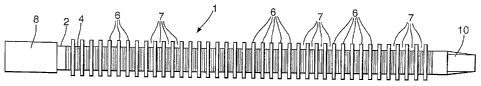
Referring to Fig. 1 there is shown a wellbore
screen 1 for use in a wellbore (referred to hereinafter)
for the production of oil. The screen 1 comprises a
tubular member 2 provided with a filter layer 4 extending
around the tubular member 2 and a plurality of swelleable
elements in the form of rings 6 extending around the
filter layer 4. The rings 6 are arranged at regular
spacings along the tubular member 2 thereby defining a
plurality of annular compartments 7, each compartment 7
being located between two adjacent rings 6. The filter
layer 4 has a sieve opening size adapted to prevent flow
of particles from the wellbore wall into the tubular
member 2 thereof. The rings 6 are made of an elastomer
which swells upon contact with oil produced from the
earth formation, the elastomer being for example EPDM
rubber. The tubular member 2 is at it ends provided with
respective connector portions 8, 10 for connecting the
wellbore screen to a production conduit (not shown) for
the flow of produced hydrocarbon fluid to a production
facility (not shown) at surface.
In Fig. 2 is shown a wellbore screen 12 similar to
the wellbore screen 1 of Fig. 1, except that the
CA 02570057 2006-12-11
WO 2006/003113 PCT/EP2005/052948
- 6 -
screen 12 comprises a swelleable element in the form of a
sleeve 14 instead of the rings 6 of the Fig. 1
embodiment. The sleeve 14 is provided with a mesh of
compartments in the form of substantially rectangular
through-openings 16. Similarly to the rings 6 of the
Fig. 1 embodiment, the sleeve is made of an oil
swelleable rubber such as EPDM.
In Fig. 3 is shown a wellbore screen 18 similar to
the wellbore screen 12 of Fig. 2, except that the
swelleable element is a sleeve 16 provided with a mesh of
substantially circular through-openings 20 instead of the
rectangular through-openings 16 of the sleeve 14.
In Fig. 4 is shown the wellbore screen 1 when
arranged in a wellbore 22 formed in the earth formation
24, whereby the rings 6 are in their unexpanded state,
i.e. before swelling upon contact with hydrocarbon fluid
from the earth formation 24. The filter layer 4 is shown
partly broken away to indicate perforations 26 arranged
in the wall of tubular member 2.
In Fig. 5 is shown the wellbore screen 1 when
arranged in the wellbore 22, after the rings 6 have
expanded due to contact with hydrocarbon fluid from the
earth formation 24. Similarly to Fig. 4, the filter
layer 4 is shown partly broken away.
In Fig. 6 is shown a wellbore screen 30 largely
similar to the screen of Fig. 1. The screen 30 has only
three rings 6 of swelleable elastomer, such as EPDM
rubber. Furthermore, the rings 6 are arranged directly
around the tubular member 2 and locked in place by
respective steel rings 32 which are fixedly connected the
tubular element 2, for example by welding. Also, instead
of one filter layer as in the previous embodiments, the
screen 30 has two separate filter layers 4 whereby each
CA 02570057 2006-12-11
WO 2006/003113
PCT/EP2005/052948
- 7 -
filter 4 layer is arranged between two adjacent rings 6.
This embodiment has the advantage that the screen 30 can
be easily assembled by sliding the steel rings 32, the
elastomer rings 6 and the filter layers 4 over the
tubular element 2. If necessary, the steel rings 32 can
then be welded to the tubular element 2.
For ease of reference in the above figures, not all
rings, compartments, through-openings and perforations
have been indicated with a reference sign.
During normal use the wellbore screen 1 of Figs. 1, 4
and 5 is lowered into the wellbore 22 and positioned in
the hydrocarbon producing zone of the earth formation 24.
When the wellbore 22 is taken in production, hydrocarbon
fluid, such as natural gas or crude oil, flows from the
wellbore 22 via the filter layer 4 into the tubular
member 2. Thus the hydrocarbon fluid flows along the
rings 6 which thereby swell from their unexpanded mode
(Fig. 4) to their expanded mode (Fig. 5). Upon swelling
the rings 6 become pressed against the wall of the
wellbore 22 so that flow of hydrocarbon fluid along the
outside of the rings 6 from one of said compartments 7
into another of said compartments 7 is substantially
prevented. It is thereby achieved that sand or clay
particles which may have locally entered the stream of
hydrocarbon fluid, are confined to one or a few
compartments 7 only so that spreading of such particles
along the entire length of the filter layer 4, which
otherwise could lead to clogging of the entire filter
layer, is thereby prevented.
Normal use of the wellbore screen 32 of Fig. 6 is
similar to normal use of the wellbore screen 1.
Normal use of the wellbore screen 12, 18 of
respective Figs. 2, 3 is similar to normal use of the
CA 02570057 2006-12-11
WO 2006/003113
PCT/EP2005/052948
- 8 -
wellbore screen 1, except that sand or clay particles
which have locally entered the stream of hydrocarbon
fluid, are confined to one or a few of the respective
rectangular through-openings 16 (wellbore screen 12) or
circular through-openings (wellbore screen 18).
Instead of all rings of the Fig. 1 embodiment being
made of an elastomer which swells upon contact with oil
produced from the earth formation, one or more of the
rings can be made of a material which swells upon contact
with water from the earth formation. For example the
rings can include a first set of rings susceptible of
swelling in hydrocarbon fluid and a second set of rings
susceptible of swelling in formation water, whereby the
rings of the first and second sets are arranged in
alternating order.