Note: Descriptions are shown in the official language in which they were submitted.
CA 02570147 2006-12-07
WO 2005/124396
PCT/US2005/020585
PHASE-ALTERNATED CARR-PURCELL NMR ECHO SEQUENCE
Martin Blanz & Thomas Kruspe
BACKGROUND OF THE INVENTION
1. Field of the Invention
[0001] The present invention relates to the field of Nuclear Magnetic
Resonance
logging of geological formations. Specifically, the invention is a method of
phase-
alternated RF induction of nuclear spins.
2. Description of the Related Art
[0001] A variety of techniques are utilized in determining the
presence and
estimation of quantities of hydrocarbons (oil and gas) in earth formations.
These
methods are designed to determine formation parameters, including among other
things, the resistivity, porosity and permeability of the rock formation
surrounding the
wellbore drilled for recovering the hydrocarbons. Typically, the tools
designed to
provide the desired information are used to log the wellbore. Much of the
logging is
done after the well bores have been drilled. More recently, wellbores have
been
logged while drilling, which is referred to as measurement-while-drilling
(MWD) or
logging-while-drilling (LWD).
[0002] One recently evolving technique involves utilizing Nuclear
Magnetic
Resonance (NMR) logging tools and methods for determining, among other things,
porosity, hydrocarbon saturation and permeability of the rock formations. The
NMR
logging tools are utilized to excite the nuclei of fluids in the geological
formations
surrounding the wellbore so that certain parameters such as spin density,
longitudinal
relaxation time (generally referred to in the art as Ti) and transverse
relaxation time
(generally referred to as T2) of the geological formations can be measured.
From such
measurements, porosity, permeability and hydrocarbon saturation are
determined,
which provides valuable information about the make-up of the geological
formations
and the amount of extractable hydrocarbons.
[0003] The NMR tools generate a uniform or near uniform static
magnetic field in
a region of interest surrounding the wellbore. NMR is based on the fact that
the
nuclei of many elements have angular momentum (spin) and a magnetic moment.
1
CA 02570147 2006-12-07
WO 2005/124396
PCT/US2005/020585
The nuclei have a characteristic Larmor resonant frequency related to the
magnitude
of the magnetic field in their locality. Over time the nuclear spins align
themselves
along an externally applied magnetic field. This equilibrium situation can be
disturbed by a pulse of an oscillating magnetic field, which tips the spins
with
resonant frequency within the bandwidth of the oscillating magnetic field away
from
the static field direction. The angle 0 through which the spins exactly on
resonance
are tipped is given by the equation:
= yBitp /2 (1)
where is the gyromagnetic ratio, B1 is the magnetic flux density amplitude of
the
sinusoidally oscillating field and tp is the duration of the RF pulse.
[0004] After tipping, the spins precess around the static field at a
particular
frequency known as the Larmor frequency coo, given by
co = 7130 (2)
where Bo is the static field intensity. At the same time, the spins return to
the
equilibrium direction (i.e., aligned with the static field) according to an
exponential
decay time known as the spin-lattice relaxation time or T1. For hydrogen
nuclei, 7/27r
= 4258 Hz/Gauss, so that a static field of 235 Gauss would produce a
precession
frequency of 1 MHz. T1 of fluid in pores is controlled totally by the
molecular
environment and is typically ten to one thousand milliseconds in rocks.
[0005] At the end of a 0 = 90 tipping pulse, spins on resonance are
pointed in a
common direction perpendicular to the static field, and they precess at the
Larmor
frequency. However, because of inhomogeneity in the static field due to the
constraints on tool shape, imperfect instrumentation, or microscopic material
heterogeneities, each nuclear spin precesses at a slightly different rate.
Hence, after a
time long compared to the precession period, but shorter than T1, the spins
will no
longer be precessing in phase. This de-phasing occurs with a time constant
that is
commonly referred to as T2* if it is predominantly due to the static field
inhomogeneity of the apparatus, and as T2 if it is due to properties of the
material.
[0006] One method to create a series of spin echoes is due to Carr and
Purcell.
Discussed in Fukusima, E., and Roeder, B., "Experimental Pulse NMR: A Nuts and
2
CA 02570147 2006-12-07
WO 2005/124396 PCT/US2005/020585
Bolts Approach", 1981, as well as Slichter, C. P., "Principles of Magnetic
Resonance", 1990. The pulse sequence starts with a delay of several T1 to
allow spins
to align themselves along an applied static magnetic field axis. Then a 90
tipping
pulse is applied to rotate the spins into the transverse plane, where they
precess with
angular frequency determined by local magnetic field strength. The spin system
loses
coherence in accordance with time constant, T2*. After a short time (tap) a
180
tipping pulse is applied which continues to rotate the spins, inverting their
position in
the transverse plane. The spins continue to precess, but now their phases
converge
until they momentarily align a further time tcp after application of the 180
pulse. The
realigned spins induce a voltage in a nearby receiving coil, indicating a spin
echo.
Another 180 pulse is applied after a further time tap, and the process is
repeated many
times, thereby forming a series of spin echoes with spacing 2 tap.
[0007] While the Can-Purcell sequence would appear to provide a
solution to
eliminating apparatus induced inhomogeneities, it was found by Meiboom and
Gill
that if the duration of the 180 pulses in the Can-Purcell sequence were even
slightly
erroneous so that focusing is incomplete, the transverse magnetization would
steadily
be rotated out of the transverse plane. As a result, substantial errors would
enter the
T2 determination. Thus, Meiboom and Gill devised a modification to the Can-
Purcell
pulse sequence such that after the spins are tipped by 90 and start to de-
phase, the
carrier of the 180 pulses is phase shifted by 71/2 radians relative to the
carrier of the
90 pulse. This phase change causes the spins to rotate about an axis
perpendicular to
both the static magnetic field axis and the axis of the tipping pulse. If the
phase shift
between tipping and refocusing pulses deviates slightly from n/2 then the
rotation axis
will not be perfectly orthogonal to the static and RF fields, but this has
negligible
effect. For an explanation, the reader is referred to a detailed account of
spin-echo
NMR techniques, such as in Fukushima and Roeder, "Experimental Pulse NMR: A
Nuts and Bolts Approach". As a result any error that occurs during an even
numbered
pulse of the CPMG sequence is cancelled out by an opposing error in the odd
numbered pulse. The CPMG sequence is therefore tolerant of imperfect spin tip
angles. This is especially useful in a well logging tool which has
inhomogeneous and
imperfectly orthogonal static and pulse-oscillating (RF) magnetic fields.
3
CA 02570147 2006-12-07
WO 2005/124396
PCT/US2005/020585
[0008] A typical CPMG sequence is shown in Fig. 2. Excitation pulse
201 rotates
the magnetic spins into the xy-plane. Refocusing pulses (202a, 202b, 202c,
202d,
202e ...) are applied following the excitation pulse, each of which induce a
spin echo
(203a, 203b, 203c, 203d, 203e ...). Although the illustration of Fig. 2 is
limited to
five refocusing pulses, in reality there can be hundreds or thousands of
pulses and
echoes. The time between the centers of two subsequent echoes is called inter-
echo
spacing TE. The curve linking the echo maxima is the echo decay curve 210. All
refocusing pulses have the same phase. The phase of the excitation pulse is
offset by
either +90 or -900. Some characteristics of the CPMG sequence are:
a) The excitation pulse tips the z-magnetization (aligned with the static
magnetic field) into the xy-plane perpendicular to the z-axis.
b) The refocusing pulses rotate the magnetization by 180 .
c) If all pulses have the same amplitude, then refocusing pulses are twice
the length of the excitation pulse.
d) All refocusing pulses have the same phase, but the excitation pulse
phase is 90 different.
The last characteristic d) was the novelty when the CPMG was first published.
This
phase shift between excitation pulse and refocusing pulses causes a
compensation of
rephasing angle errors. With the phase shift the errors correct themselves
with every
second echo.
[0009] As noted above, the CPMG sequence tolerates imperfect spin tip
angles.
As an example, U.S. Patent No. 6,466,013, to Hawkes et al. discusses a method,
referred to as the Optimized Rephasing Pulse Sequence (ORPS), which optimizes
the
timings for inhomogeneous Bo and Bi fields to obtain maximum NMR signal or,
alternatively, to save radio frequency power. A pulsed RF field is applied
which tips
the spins on resonance by the desired tip angle for maximum signal, typically
90
tipping pulse. A refocusing pulse having a spin tip angle substantially less
than 180
is applied with carrier phase shifted by typically ic/2 radians with respect
to the 90
tipping pulse. Although the refocusing pulses result in spin tip angles less
than 180
through the sensitive volume, their RF bandwidth is closer to that of the
original 90
pulse. Hence more of the nuclei originally tipped by 90 are refocused,
resulting in
larger echoes than would be obtained with a conventional 90 refocusing pulse.
ORPS is not a CPMG sequence. The timing and duration of RF pulses are altered
4
CA 02570147 2006-12-07
WO 2005/124396 PCT/US2005/020585
trom conventional CPMG to maximize signal and minimize RF power consumption.
Nevertheless ORPS still possesses the characteristic d), i.e. the excitation
pulse is
phase shifted by 900 with respect to the refocusing pulses. An additional
forced
recovery pulse at the end of an echo train may be used to speed up the
acquisition
and/or provide a signal for canceling the ringing artifact.
[0010] The NMR echoes of an echo sequence like CPMG or ORPS contain,
in
addition to the true NMR signal, DC offset and ringing. Radio frequency pulses
typically cause ringing (magneto-acoustic, electronic) after each pulse. This
ringing
can be larger than the NMR signal itself. It must be avoided or subtracted
before
further processing of the NMR data. DC offset of the NMR signals must also be
determined and subtracted. We refer to the DC offset and ringing as non-NMR
signals to distinguish them from NMR signals from nuclei in earth formations.
[0011] Subtraction methods for reducing ringing and offset are known in the
prior
art. The standard method for this is the use of a Phase Alternated Pair (PAP)
of echo
sequences.
[0012] In order to cancel the electronic offsets and antenna ringing,
it is
customary to combine two CPMG measurements of opposite phase. These pairwise-
combined measurements are called phase-alternate-pair (PAP) echo trains and
these
constitute the datasets that are submitted to processing. U.S. Patent No.
6,624,629, to
Kleinberg et al., discusses a standard PAP method. In a PAP sequence, two CPMG
or
ORPS sequences are acquired. In one sequence, the excitation pulse rotates the
nuclear spins by -90 with respect to the refocusing pulses, and in the other
sequence,
the excitation pulse rotates the nuclear spin by +90 with respect to the
refocusing
pulses. The inverted phase of the alternate excitation pulse causes a phase
inversion
of all the echoes. Meanwhile the effects of ringing due to the refocusing
pulses are
unaffected by the inversion of the excitation pulses. A typical PAP sequence
is
shown in Fig. 3. By subtracting the acquired echo data of the lower sequence
of Fig.
3 from those of the upper sequence, the ringdowns of all refocusing pulses and
the
offsets are subtracted while the NMR echoes are added.
5
CA 02570147 2006-12-07
WO 2005/124396 PCT/US2005/020585
[0013] A condition for proper ringdown and offset subtraction of the
PAP is that
the ringdown and offset are repeatable, i.e. identical in both sequences that
make up
the PAP.
[0014] U.S. Patent No. 6,522,138, to Heaton and U.S. Patent No. 6,525,534,
to
Akkurt et al. discusses method of reducing ringing effects. Heaton '138
discusses
retrieving corrected individual measurements from sequentially parwise-
combined
measurements. Such sequentially pairwise-combined measurements may include
PAP NMR measurements from well logging. One of the methods comprises
providing an initial estimate for a first one of the corrected individual
measurement,
deriving temporary estimates for other ones of the corrected individual
measurements
by subtracting the initial estimate from the first sequentially pairwise-
combined
measurements to produce an estimate for a second one of the corrected
individual
measurements, and repeating the subtraction from each of the next sequentially
pairwise-combined measurements until temporary estimates for each of the
corrected
individual measurements are obtained, and correcting errors in the temporary
estimates to generate error-corrected estimates by filtering an alternating
error
component associated with the initial estimate. Akkurt 534 discusses improving
the
vertical resolution of NMR logs based on data acquisition methods and signal
processing techniques that need not apply PAPS. The method of Akkurt '534 is
based
on reducing the level of coherent non-formation signals, but providing
estimates of
these signals and removing the estimates from the underlying NMR pulse echo
trains.
[0015] Alternate methods for improving resolution are discussed in the
prior art.
U.S. Patent Appl. No.2004/0008027, of Prammer, discusses providing, in a
geologic
formation, at least one first plurality of phase alternated NMR pulses at a
first
frequency (F1), and receiving at least one corresponding first signal in
response. The
method includes providing, not necessarily simultaneously, at least one second
plurality of phase alternated NMR pulses at a second frequency (F2), and
receiving at
least one corresponding second signal in response thereto. In an embodiment of
Prammer a difference between the first and second frequencies is a function of
one or
more of an inter-echo spacing, a time delay between and excitation pulse and a
data
acquisition window, and a rate for generating echoes. The received first and
second
signals are combined to obtain a corrected NMR signal.
6
CA 02570147 2006-12-07
WO 2005/124396 PCT/US2005/020585
[0016] U.S. Patent No. 6,624,629, to Speier et al., uses a controller
adapted to
cause the RF transmitter to transmit RF pulse sequences into a sample and for
each
different RF pulse sequence, vary an estimated pulse width for producing a
predetermined flip angle by a different scaling facto to produce flip angles
near the
predetermined flip angle. The controller is adapted to receive spin echo
signals in
response to the transmission of the RF pulse sequences; determine a property
of the
sample in response to the spin echo signals; and use the spin echo signals to
determine
an optimal pulse width for producing the predetermine flip angle.
[0017] The technique of PAP depends on the repeatability of offset and
ringing.
Between the acquisition of the two echo sequences may be a remagnetization
delay of
up to 10 seconds. In reality, both offset and ringing may not be stable over
such a
long time. Yet another disadvantage of PAP is that a complete NMR measurement
takes at least two echo sequences with a (long) remagnetization time between
them.
For fast NMR (wireline) logging this is a disadvantage because the aperture of
the
NMR measurement along the borehole axis is increased. Therefore there are
quite a
number of reasons to look for alternatives to PAP for subtracting offset and
ringing
from the NMR signal. The present invention fulfills those needs.
SUMMARY OF THE INVENTION
[0019] The present invention is a_method of and apparatus for evaluating an
earth
formation. A nuclear magnetic resonance (NMR) device is conveyed within a
borehole in the earth formation. A magnet on the NMR device produces a static
magnetic field in a volume of the earth formation. The static magnetic field
aligns
nuclear spins in the formation. The earth formation is pulsed by at least one
sequence
of radio frequency (RF) pulses. The RF pulse sequence includes an excitation
pulse
with a tip angle substantially equal to 90 and a plurality of groups of
refocusing
pulses, each group including a phase-alternated pair of refocusing pulses, one
pulse of
said phase-alternated pair having a phase substantially equal to a phase of
the
excitation pulse. The pulsing may be done by an antenna assembly. Signals
resulting
from the application of the pulses are received. The resulting signals are
processed to
give corrected signals in which a non formation signal has been reduced. The
processing may be done by a processor. In one embodiment of the invention, the
signals are spin echo signals.
7
CA 02570147 2006-12-07
WO 2005/124396 PCT/US2005/020585
[0020] In one embodiment of the invention, the non-formation signal is a DC
offset.
In another embodiment of the invention, each group of refocusing pulses
includes
refocusing pulses that are phase shifted plus or minus 900 to a phase of the
excitation
pulse: this enables removal of ringing.
[0021] The refocusing pulses may have tip angles substantially equal to 180 .
In
another embodiment of the invention, the refocusing pulses have tip angles
between
90 and 180 . The corrected signals may be processed using a processor to
determine
formation properties such as total porosity, effective porosity, BVI, BVM,
and, T2
distribution. The NMR apparatus may be part of a bottom hole assembly used for
drilling a borehole or may be conveyed on a wireline.
BRIEF DESCRIPTION OF THE DRAWINGS
[0022] The present invention is best understood with reference to the
accompanying
figures in which like numerals refer to like elements and in which:
FIG. 1 (Prior Art) shows a measurement-while-drilling tool suitable for use
with the
present invention;
FIG. 2 (Prior Art) shows a typical CPMG sequence;
FIG. 3 (Prior Art) shows a phase-alternated pair sequence (PAPS);
FIG. 4 shows an exemplary pulse sequence of the present invention;
FIG. 5 shows a variation on the pulse sequence of the present invention;
FIG. 6 shows a simulation of an ORPS sequence;
FIG. 7 shows a simulation of a PACP spin echo sequence; and
FIG. 8a to 8e shows a simulation and further processing of the X (x -x y y)õ
sequence,
DETAILED DESCRIPTION OF THE INVENTION
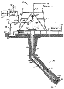
[0022] Fig. 1 shows a schematic diagram of a drilling system 10 with a
drillstring
20 carrying a drilling assembly 90 (also referred to as the bottom hole
assembly, or
"BHA") conveyed in a "wellbore" or "borehole" 26 for drilling the wellbore.
The
drilling system 10 includes a conventional derrick 11 erected on a floor 12
which
supports a rotary table 14 that is rotated by a prime mover such as an
electric motor
8
CA 02570147 2006-12-07
WO 2005/124396 PCT/US2005/020585
(not shown) at a desired rotational speed. The drillstring 20 includes a
tubing such as
a drill pipe 22 or a coiled-tubing extending downward from the surface into
the
borehole 26. The drillstring 20 is pushed into the wellbore 26 when a drill
pipe 22 is
used as the tubing. For coiled-tubing applications, a tubing injector, such as
an
injector (not shown), however, is used to move the tubing from a source
thereof, such
as a reel (not shown), to the wellbore 26. The drill bit 50 attached to the
end of the
drillstring breaks up the geological formations when it is rotated to drill
the borehole
26. If a drill pipe 22 is used, the drillstring 20 is coupled to a drawworks
30 via a
Kelly joint 21, swivel 28, and line 29 through a pulley 23. During drilling
operations,
the drawworks 30 is operated to control the weight on bit, which is an
important
parameter that affects the rate of penetration. The operation of the drawworks
is well
known in the art and is thus not described in detail herein.
[0023] During drilling operations, a suitable drilling fluid 31 from a
mud pit
(source) 32 is circulated under pressure through a channel in the drillstring
20 by a
mud pump 34. The drilling fluid passes from the mud pump 34 into the
drillstring 20
via a desurger (not shown), fluid line 38 and Kelly joint 21. The drilling
fluid 31 is
discharged at the borehole bottom through an opening in the drill bit 50. The
drilling
fluid 31 circulates uphole through the annular space 27 between the
drillstring 20 and
the borehole 26 and returns to the mud pit 32 via a return line 35. The
drilling fluid
acts to lubricate the drill bit 50 and to can-y borehole cutting or chips away
from the
drill bit 50. A sensor S1 typically placed in the line 38 provides information
about the
fluid flow rate. A surface torque sensor S2 and a sensor S3 associated with
the
drillstring 20 respectively provide information about the torque and
rotational speed
of the drillstring. Additionally, a sensor (not shown) associated with line 29
is used to
provide the hook load of the drillstring 20.
[0024] In one embodiment of the invention, the drill bit 50 is rotated
by only
rotating the drill pipe 22. In another embodiment of the invention, a downhole
motor
55 (mud motor) is disposed in the drilling assembly 90 to rotate the drill bit
50 and the
drill pipe 22 is rotated usually to supplement the rotational power, if
required, and to
effect changes in the drilling direction.
[0025] In an exemplary embodiment of Fig. 1, the mud motor 55 is
coupled to the
9
CA 02570147 2006-12-07
WO 2005/124396 PCT/US2005/020585
drill bit 50 via a drive shaft (not shown) disposed in a bearing assembly 57.
The mud
motor rotates the drill bit 50 when the drilling fluid 31 passes through the
mud motor
55 under pressure. The bearing assembly 57 supports the radial and axial
forces of
the drill bit. A stabilizer 58 coupled to the bearing assembly 57 acts as a
centralizer
for the lowermost portion of the mud motor assembly.
[0026] In one embodiment of the invention, a drilling sensor module
59 is placed
near the drill bit 50. The drilling sensor module contains sensors, circuitry
and
processing software and algorithms relating to the dynamic drilling
parameters. Such
parameters typically include bit bounce, stick-slip of the drilling assembly,
backward
rotation, torque, shocks, borehole and annulus pressure, acceleration
measurements
and other measurements of the drill bit condition. A suitable telemetry or
communication sub 72 using, for example, two-way telemetry, is also provided
as
illustrated in the drilling assembly 90. The drilling sensor module processes
the
sensor information and transmits it to the surface control unit 40 via the
telemetry
system 72.
[0027] The communication sub 72, a power unit 78 and an MWD tool 79
are all
connected in tandem with the drillstring 20. Flex subs, for example, are used
in
connecting the MWD tool 79 in the drilling assembly 90. Such subs and tools
form
the bottom hole drilling assembly 90 between the drillstring 20 and the drill
bit 50.
The drilling assembly 90 makes various measurements including the pulsed
nuclear
magnetic resonance measurements while the borehole 26 is being drilled. The
communication sub 72 obtains the signals and measurements and transfers the
signals,
using two-way telemetry, for example, to be processed on the surface.
Alternatively,
the signals can be processed using a downhole processor in the drilling
assembly 90.
[0028] The surface control unit or processor 40 also receives signals
from other
downhole sensors and devices and signals from sensors S1-S3 and other sensors
used
in the system 10 and processes such signals according to programmed
instructions
provided to the surface control unit 40. The surface control unit 40 displays
desired
drilling parameters and other information on a display/monitor 42 utilized by
an
operator to control the drilling operations. The surface control unit 40
typically
includes a computer or a microprocessor-based processing system, memory for
CA 02570147 2006-12-07
WO 2005/124396 PCT/US2005/020585
storing programs or models and data, a recorder for recording data, and other
peripherals. The control unit 40 is typically adapted to activate alarms 44
when
certain unsafe or undesirable operating conditions occur.
[0029] Fig. 4 shows an exemplary pulse sequence of the present invention.
This
pulse sequence is a variation on the original CP pulse sequence. The echo
sequence
of Fig. 4 has been suggested, for example, in Fukushima and Slichter but
without
foreseeing their advantage in NMR logging in very inhomogeneous fields. Since
we
have not a name for this sequence in the literature, we refer to it herein as
the Phase
Alternated Can Purcell (PACP) sequence.
[0030] A static magnetic field is introduced into a volume, the
direction of the
magnetic field defining a coordinate system wherein the +Z axis is
substantially
aligned along the static magnetic field in the volume and X and Y axes define
a plane
substantially perpendicular to said static magnetic field. For discussion
purposes, the
applied RF pulses rotate the nuclear spins along the X-axis.
[0031] The following is a concise notation for the pulse sequences
used in the
present document.
x (y)n denotes an x excitation pulse followed by n y pulses;
' -x (y)n denotes a ¨x excitation pulse followed by n y pulses; and
x (y y ¨y ¨y)n denotes an x excitation pulse followed by n repetitions of (y y
¨y ¨y)
pulses. The latter may be called a CPMG derivative because the sequence uses a
refocusing pulse phase shift of +71. 12 with respect to the excitation pulse
and not all
refocusing pulses have the same phase.
[0032] The phase alternated Can Purcell sequence is denoted by X (x -
x)n or
X (-x x)n. An excitation pulse 401 is applied so as to tilt the nuclear spins
into the
plane transverse to the static magnetic field. The rotation of the spins due
to the
excitation pulse occurs along the X-axis, so that nuclear spins are aligned
along the Y-
axis directly after the completion of the excitation pulse. The excitation
pulse
typically has a tipping angle of around 90 . The excitation pulse is followed
after a
time tcp with phase-alternated pairs of refocusing pulses. In the pulse
sequence of Fig.
4, for example, refocusing pulses 402a, 402c, and 402e rotate the nuclear
spins +180
11
CA 02570147 2006-12-07
WO 2005/124396 PCT/US2005/020585
around the X-axis, whereas refocusing pulses 402b and 402d rotate the nuclear
spins -
1800 around the X-axis. Pulses 402a and 402b form a phase-alternate pulse
pair, as
do pulses 402c and 402d. Although the illustration of Fig. 4 shows only five
echoes,
the number of refocusing pulses is not limited in number by the present
invention.
Spin echoes (412a, 412b, 412c, 412d, 412e, ...) resulting from the phase-
alternated
refocusing pulses therefore experience a 180 phase shift from each other. It
should
be noted that the tipping angle of the refocusing pulses could by 180 (as
with a
CPMG sequence) or could be less than 180 (as with the ORPS sequence). While
the
spin echoes experience a 180 shift, the DC offset of the signal does not
experience
the same shift.
[0033] One advantage of the application of the pulse sequence of Fig.
4 is that the
resultant spin echo signals can be used to remove DC offset without the use of
a
PAPS. For example, one can combine (subtract) successive spin echoes of the
spin
echo sequence. Such subtraction enables removal of the offset while co-adding
NMR.
An exemplary algorithm for signal-removal is:
Echo 2 ¨ echo 1 = positive, offset-free echo at position midway
between echo 1 and echo 2.
Echo 2¨ Echo 3 = positive, offset-free echo at position midway
between echo 2 and echo 3.
Echo 4¨ Echo 3 = positive, offset-free echo at position midway
between echo 3 and echo 4.
Echo 4¨ Echo 5 = positive, offset-free echo at position midway
between echo 4 and echo 5.
and so forth.
In reference to Fig. 4, the above algorithm would be written as: echo 412b -
echo 412a; echo 412b - echo 412c; echo 412d - echo 412c; echo 412d - echo
412e; and so forth. The removal of the DC offset is enabled by the spin
echoes alternating in phase as the DC offset remains in phase.
[0034] Fig. 6 shows signals resulting from a simulation of an ORPS
sequence.
The echoes are each shown with in-phase 551 and quadrature components 553. In
Fig. 7, a simulation of a spin echo sequence resulting from a PACP is shown.
The
pulses are shown by 601, the real component of the echoes by 603 and the
quadrature
12
CA 02570147 2006-12-07
WO 2005/124396 PCT/US2005/020585
component of the echoes by 605. As in CPMG and ORPS, the pulse errors of the
PACP no longer accumulate but cancel. The PACP sequence works in
inhomogeneous static and RF fields as effectively as the CPMG or ORPS sequence
(depending on timing). Peak amplitudes of Fig. 7 are substantially equal to
peak
amplitudes of Fig. 6. The sequence of Fig. 7 also has the same sensitivity to
motion
as Fig. 6.
[0035] Provided ringing is negligible, the offset removal method
discussed above
avoids the need for a PAP. Therefore, an improved DC offset removal (where the
offset varies with time) is achieved. As a result, the resolution along the
borehole axis
is enhanced.
[0036] PACP by itself does not enable removal of ringing as it does
removal of
DC offset. This is because there is always the same phase relation between
each
refocusing pulse (and its resultant ringdown) and its corresponding spin echo
within a
pulse sequence. Said another way, the signs of the spin echo alternate from
echo to
echo but so do the signs of the refocusing pulses (and ringdowns). Therefore,
there is
no pairing of echoes in PACP that can be used to remove ringing while at the
same
time accumulating the NMR signal.
[0037] A PAP combination of the PACP can be constructed for reducing
ringing
effects. Like the CPMG pulse sequence, the excitation pulse of the PACP
enables
two variations. A PAPS sequence can be constructed from the two PACP sequences
for reducing ringing effects. Fig. 5 shows a second pulse sequence of the
present
invention. Fig. 5 is similar to Fig. 4 in that an excitation pulse 501 is
applied
followed by alternating refocusing pulses (502a, 502b, 502c, 502d, 502e ).
Whereas the excitation pulse 401 of Fig. 4 rotates the nuclear spins in the
+90
direction around the X-axis, the excitation pulse 501 of Fig. 5 rotates the
nuclear spins
in the -90 direction around the X-axis. The refocusing pulses of Fig. 5 are
in phase
with the refocusing pulses of Fig. 4. As a result, the ringdown of the
refocusing
pulses is identical in both sequences (e.g. the phase of ringdown 420a is the
same as
the phase of ringdown 520a). However, the spin echoes of Fig. 5 are inverted
in
phase from the corresponding spin echoes of Fig. 4. Due to these phase
relations
between spin echoes and ringdowns in Figs. 4 and 5, when subtracting the two
variant
13
CA 02570147 2006-12-07
WO 2005/124396 PCT/US2005/020585
spin echo sequences (i.e. the signals due to refocusing pulses 502a and 402a),
the
ringdowns (520a, 420a) are subtracted simultaneously with the addition of the
spin
echoes (512a, 412a).
[0038] An alternative PAPS can be constructed where both PACP sequences of
the PAPS have the same excitation pulse phase but all the refocusing pulses
have been
phase-inverted in one sequence with respect to the other.
[0039] The pulse times and delay times of a pulse sequence of the
present
invention can be optimized according to methods discussed in Hawkes '013 and
in
Slichter.
[0040] We next address the issue of removing ringing using a variant
of the PACP
sequence in combination with CPMG or ORPS sequences. Eight such sequences are
possible, denoted by:
X (x -x y y).,
X (y y x
X (-x x y y).,
X (y y -x x)n,
X (x -x -y
X (-y -y x
X (-x x -y -y). and
X (-y -y x -x)õ..
As an example a NMR simulation and further processing of the first of these
sequences are presented next in FIG. 8a to 8e. A precondition is that the
ringing
phase really follows the pulse phase, not only if the pulse is inverted but
also when
the pulse phase is changed by 90 . As all the above sequences contain x, -x
and y or -
y pulses the echo phases first need phase rotating for the same ringing phase
before
we can subtract successive echoes to remove ringing. At the same time this
method
excludes offset removal because the offset is also rotated by say 90 and
hence is no
longer subtracted when we subtract two echoes. Therefore the offset must be
removed either by one of the ways explained above or by a PAP of these
sequences.
Using a PAP we would first remove ringing for each individual sequence and
remove
offset afterwards by PAP. In Fig. 8a to 8e complex (i.e. magnitude and phase)
14
CA 02570147 2006-12-07
WO 2005/124396 PCT/US2005/020585
entities, like pulses, echoes or echo amplitudes are shown. The real (in-
phase) part is
always drawn as a solid line while the imaginary (quadrature) part is shown as
a
dashed or dotted line.
[0040] Fig. 8a shows the NMR simulation with x and -x pulses as solid
rectangles
621 and y pulses 623 as dashed rectangles and the real 625 and imaginary 627
parts of
the spin echo signals. The pulses 621 form pairs with alternating polarity
while the
pulses 623 have 900 phase shifts (and form pairs with the same relative
polarity).
After rotation of the individual pulses and echoes of Fig. 8a to give all
ringing the
same phase, the results are shown in Fig. 8b. Specifically, all echoes are
rotated by a
phase shift that is the inverse of the preceding pulse phase. This results in
all echoes
showing the same ringing. For the display, the same is done with the phase of
the
pulses, i.e. all pulses are now displayed with the same phase. This is a check
that the
phase correction has been properly applied. 631 shows the pulses while 633 and
635
show the echoes.
[0041] Subtraction and division by two of successive echoes of Fig. 8b gives
the
results of Fig. 8c where the real part is denoted by 651 and the imaginary
part by 653.
Fig. 8d shows the average of four points, sampled at 10 tts interval, over
each echo
maximum for the real 661 and imaginary 663 components. Hence each pair of
points
for the same n (echo counter, horizontal axis) represents a complexe effective
amplitude of the rith echo. Individual phase correction of each echo of Fig.
8d gives
the results of Fig. 8e with the real part given by 671 and the imaginary part
by 673.
[0042] It is noted that if only every second echo of Fig. 8e is used (remember
that
each echo in this figure is already composed of two echoes) the amplitudes and
signal-to-noise rations are about 30% less than the reference amplitudes we
would get
by processing the echoes of Fig. 6 or 7 in the same way, i.e. averaging 4
points over
the top of each echo. However, the processing sequence shows that in principle
it is
possible to combine CPMG (or ORPS) and PACP, but because the signal phases do
not match perfectly, we lose SNR. The processing is more complicated than that
for
CPMG or ORPS in that every individual echo needs individual phase rotation and
stimulated echo correction. However, if non-repeatable ringing is a serious
problem
then this sequence may be the lesser evil. The non-repeatable ringing can
arise, for
CA 02570147 2012-09-13
example, from quartz crystals in earth formations: quartz is a major component
of
sandstones. In MWD measurements (where the rate of penetration is low), the
ringing from quartz crystals is more likely to be repeatable than in wireline
applications where the logging speed is much higher. The offset is less likely
to vary
with time. For this reason, with the pulse sequence of Fig. 8, the ringing
should
preferably be removed first and then the offset removed using a PAP.
[0043] Once the non-NRM signal (ringing or offset) has been removed, the
corrected
signals can then be analyzed using prior art methods to obtain properties of
the earth
formation. These include total porosity, effective porosity, BVI, BVM, and T2
distributions.
[0044] The present invention has been discussed above with respect to
measurements
made by a measurement-while-drilling (MWD) assembly. This is not intended to
be a
limitation and, in particular, the method is equally applicable to
measurements made
using a wireline device or coiled tubing.
100451 While the foregoing disclosure is directed to the specific embodiments
of the
invention, various modifications will be apparent to those skilled in the art.
The scope
of the claims should not be limited by the preferred embodiments set forth in
the
examples, but should be given the broadest interpretation consistent with the
description as a whole.
16