Note: Descriptions are shown in the official language in which they were submitted.
CA 02570339 2010-09-17
METHOD AND DEVICE FOR MEASURING AND ADJUSTING THE EVENNESS
AND/OR TENSION OF A STAINLESS STEEL STRIP OR
STAINLESS STEEL FILM DURING COLD ROLLING IN A 4-ROLL STAND,
PARTICULARLY IN A 20-ROLL
SENDZIMIR ROLL STAND
The invention concerns a method and a device for
measuring and adjusting the flatness and/or the strip
tension of a high-grade steel strip or a high-grade steel
foil during cold rolling in a cluster mill, especially in a
20-roll Sendzimir rolling mill, with at least one closed-
loop control system comprising several actuators, wherein
the actual strip flatness in the runout of the cluster mill
is measured by a flatness measuring element on the basis of
the strip tension distribution over the width of the strip.
Cluster mills of this type have a split-block or
monoblock design, wherein the upper and lower sets of rolls
can be adjusted independently of each other, and this can
result in different housing frames.
The method mentioned at the beginning is known from EP 0
349 885 Bl and comprises the formation of measured values
which characterize the flatness, especially the tensile stress
1
CA 02570339 2006-12-14
distribution, on the runout side of the rolling stand, and,
depending on these measured values, actuators of the rolling
mill are actuated, which belong to at least one closed-loop
control system for the flatness of the rolled sheets and strips.
In order then to reduce the different time response of the
actuators of the rolling mill, the previously known method
proposes that the speeds of the different actuators be adapted
to one another and that their regulating distances be evened
out. However, this fails to catch other sources of errors.
Another previously known method (EP 0 647 164 Bl), which is
a method for obtaining input signals in the form of roll gap
signals, for control elements and controllers for actuators of
the work rolls, measures the tension distribution transversely
with respect to the strip material, wherein the flatness errors
are derived from a mathematical function in which the squares of
the deviations are to assume a minimum, which is determined by a
matrix, with the number of measuring points, the number of rows,
the number of base functions, and the number of roll gaps in the
measuring points. This procedure also fails to consider the
flatness errors that occur under practical conditions and their
development.
The objective of the invention is to achieve altered
2
CA 02570339 2006-12-14
adjustment behavior of the individual actuators on the basis of
more accurately measured and analyzed flatness errors in order
to achieve greater flatness of the final product, so that the
rolling speed can also be increased.
In accordance with the invention, this objective is
achieved by determining a flatness error by comparison of a
tension vector with a predetermined reference curve, then
decomposing the curve of the flatness error over the width of
the strip into proportional tension vectors in an analytical
module in a mathematical approximation, and supplying the
flatness error components determined by real numerical values to
corresponding control modules to actuate the corresponding
actuators. The advantage of this method is that it ensures a
stable rolling process with a minimum rate of strip breakage and
thus an increase in the potential rolling speed. Furthermore,
the work of the operating personnel is simplified by the
automatic adjustment of the flatness actuators to altered
conditions, even in the case of incorrect settings. In
addition, more uniform product quality is achieved,
independently of the qualifications of the personnel. Moreover,
the computation of the influencing functions and a computation
of the control functions can be carried out in advance,
3
CA 02570339 2006-12-14
resulting in savings of time. The flatness control system as a
whole becomes more stable with respect to inaccuracies in the
computed control functions. The inaccuracies remain without
influence on startup. The most important components of the
flatness error are eliminated with maximum possible control
dynamics. The orthogonal components of the tension vectors are
linearly independent of one another, which rules out mutual
effects of the components among one another. The scalar
flatness error components are supplied to the individual control
modules.
In accordance with a refinement of the invention, the curve
of the flatness error over the strip width is approximated by an
eighth-order Gaussian approximation (LSQ method) and then
decomposed into the orthogonal components.
An improvement of the invention is obtained if a residual
error vector is analyzed, and the residual error vector is sent
to directly selected actuators. All flatness errors remaining
after the highly dynamic correction process, which flatness
errors can be influenced with the given influencing functions,
are eliminated by the residual error removal as part of the
available control range. Therefore, in addition to the
aforementioned orthogonal components of the flatness error, it
4
CA 02570339 2006-12-14
is advantageous also to consider a residual error, which is not
supplied to the orthogonal components described above but rather
directly to the actuators.
In accordance with additional steps, the residual error
vectors can be assigned by weighting functions, which are
derived from influencing functions of excenter actuators and
assign the total flatness error that is present to the
individual excenters.
In this regard, it is also advantageous if a magnitude of
error determined by real numerical values is formed by summation
from the residual error vectors assigned to the excenters.
In another refinement, the adjustment for the strip edges
is carried out separately within the flatness adjustment. In
this way, this type of adjustment can also possibly be
completely shut off if it is not absolutely required.
In another improvement, the horizontal shift of the inner
intermediate rolls is used as the actuator for the edge tension
control system.
To this end, it is proposed as an improvement that a
predetermined strip tension in the region of one to two
outermost covered zones of a flatness measuring roller is
adjusted separately for each edge of the strip by means of the
CA 02570339 2006-12-14
edge tension control system.
In accordance with other features of the invention, the
edge tension control system is operated optionally
asynchronously or synchronously for the two strip edges.
In this regard, the controlled variable for the edge
tension control system can be determined separately for each
edge of the strip by taking the difference between the
deviations of the two outermost measured values of the flatness
measuring roller.
In accordance with the indicated state of the art, the
device for measuring and adjusting the flatness and/or strip
tension of a high-grade steel strip or a high-grade steel foil
for a cold rolling operation in a cluster mill, especially in a
20-roll Sendzimir rolling mill, is based on at least one closed-
loop control system for actuators, which consist of hydraulic
adjustment mechanisms, excenters of the outer backup rolls,
axially shiftable tapered inner intermediate rolls, and/or their
influencing functions.
Therefore, with respect to a device, the previously stated
objective is achieved by virtue of the fact that a comparison
signal between a reference curve and the actual strip flatness
of the flatness measuring element at the input of the closed-
6
CA 02570339 2006-12-14
loop control system is put through to a first analyzer and
independent, first and second control modules for the formation
of the tension vectors and with the output to the actuator for
the swiveling hydraulic adjustment mechanisms of the set of
rolls, and that the comparison signal is simultaneously put
through to a second analyzer and another, separate, second
control module, whose computational result can be passed on to
the actuator of the excenters via control functions with a
coupling connection. In this way, the advantages associated
with the method can be realized in a device.
In another improvement of the invention, the comparison
signal between the reference curve and the actual strip flatness
is put through by the independent analyzer to the independent,
third control module for a flatness residual error, whose output
is supplied to the coupling connection for the actuator
consisting of the excenters.
In another design that continues the invention in this
sense, the comparison signal between the reference curve and the
actual strip flatness is put through by another, third
independent analyzer to an independent, fourth control module
for monitoring the edge tension control system, and its output
is connected to the actuator of the tapered inner intermediate
7
CA 02570339 2006-12-14
rolls.
Exact signal generation is assisted by the fact that a
flatness measuring element installed in the runout is connected
to the signal line of the actual strip flatness.
The remainder of the invention is designed in such a way
that, for each flatness error vector, a dynamic individual
controller is provided, which is provided as a PI controller
with dead band in the input.
In another embodiment, in addition to the first analyzer,
adaptive parameterizing means and a control display are arranged
in parallel on the input side of each individual controller.
In addition, it is advantageous for connections for control
parameters to be provided on each individual controller.
Furthermore, the dynamic individual controllers can be
connected with a control console.
A further analogy to the method steps is that, to remove
residual errors, the residual error vector cooperates via
residual error controllers with the actuators of the excenters.
Independence of the measurements on the strip edges is
achieved with respect to the device by virtue of the fact that
the edge tension control system provides an analyzer for
different strip edge zones of the flatness measuring roller, and
8
CA 02570339 2010-09-17
that two strip edge controllers are connected to each analyzer.
In a refinement of this system, the strip edge controllers are
connected with the actuators of the tapered intermediate rolls.
This makes it possible to switch the strip edge controllers
independently of each other.
Finally, it is provided that an adaptive adjustment speed
controller and a control display are connected to each set of
two strip edge controllers.
Accordingly, in one aspect, the present invention provides
a method for measuring and adjusting the flatness a of a steel
strip, especially a steel foil, for the cold rolling operation
in a cluster mill, especially in a 20-roll Sendzimir rolling
mill, which comprises the following steps: determination of an
actual distribution of the flatness of the steel strip over its
width on the basis of a measured strip tension distributed over
the strip width; determination of a flatness error by comparison
of a determined actual distribution of the flatness with a
predetermined reference curve; mathematical approximation of the
received flatness error; decomposition of an approximated
flatness error into scalar flatness error components; and
computation of a first and additional controller output signals
from the flatness error
9
CA 02570339 2010-09-17
components to activate a plurality of actuators of the
cluster mill; wherein the approximated flatness errors are
decomposed in such a way that the resulting flatness error
components are orthogonal to one another; a first actuator
in the form of a hydraulic adjustment mechanism out of the
plurality of actuators is activated in response to the
first controller output signal, which is obtained from the
first orthogonal component; each of the additional
controller output signals in the form of scalar correcting
variable components is computed on the basis of one of the
remaining orthogonal components of the flatness error; and
the scalar correcting variable components are combined into
suitable activating signals for individual excenter
actuators out of the plurality of actuators, wherein a
residual error vector is analyzed, and the residual error
vector is sent to directly selected actuators.
In another aspect, the present invention provides a
device for measuring and adjusting the flatness of a high-
grade steel strip (1) or a high-grade steel foil (la) for a
cold rolling operation in a cluster mill (2), especially in
a 20-roll Sendzimir rolling mill (2a), with at least one
closed-loop control system (4) comprising several actuators
(3), which consist of hydraulic adjustment mechanisms (17),
excenters (14a) of the outer backup rolls (18), axially
9a
CA 02570339 2010-09-17
shiftable tapered inner intermediate rolls (19) and/or
their influencing functions, wherein a comparison signal
(20) between a reference curve (9) and an actual strip
flatness (22) of the flatness measuring element (6) at an
input (23) of the closed-loop control system (4) is put
through to a first analyzer (lla) and independent, first
and second control modules (12a, 12b) for the formation of
tension vectors (8/Cl .... Cx) and with an output (24) to
the actuator (3) for swiveling hydraulic adjustment
mechanisms (17) of the set of rolls (2b), and where the
comparison signal (20) is simultaneously put through to a
second analyzer (lib) and another, separate, third control
module (12c), whose computational result (f) can be passed
on to the actuator (3) of the excenters (14a) with a
coupling connection, wherein for each flatness error (10),
a dynamic individual controller (30) is provided, which is
provided as a PI controller (31) with dead band in the
input (32).
BRIEF DESCRIPTION OF THE DRAWINGS
The specific embodiments of the invention illustrated
in the drawings are explained in greater detail below.
-- Figure 1 shows a plant configuration of a 20-roll
Sendzimir rolling mill.
9b
CA 02570339 2010-09-17
-- Figure 2 shows an enlarged section of the roll sets
in split-block design with the position determinations for
the flatness actuators.
-- Figure 3 shows a roll gap / strip width diagram
with the influencing functions of the excenters on the roll
gap profile.
-- Figure 4 shows a diagram of the change in the roll
gap over the strip width for the influence of the tapered
intermediate roll shift.
-- Figure 5A shows a diagram for the flatness residual
error (strip tension over strip width).
9c
CA 02570339 2006-12-14
error (strip tension over strip width).
-- Figure 5B shows a diagram of the assignment of the
flatness residual error to the individual excenters.
-- Figure 6 shows an overview block diagram of the flatness
control system for the 20-roll Sendzimir rolling mill.
-- Figure 7 shows a structural block diagram for Cx
control.
-- Figure 8 shows a block diagram on the structure of the
residual error removal.
-- Figure 9 shows a block diagram on the structure of the
edge tension control.
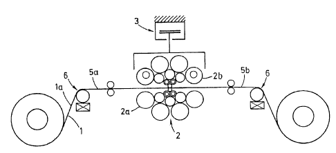
According to Figure 1, the high-grade steel strip 1 or a
high-grade steel foil la is rolled in a cluster mill 2, a 20-
roll Sendzimir rolling mill 2a, by uncoiling, rolling, and
coiling. In this regard, the sets of rolls 2b represent a
split-block design. The upper set of rolls 2b can be adjusted
by an actuator 3 and other functions. Signals, which will be
described later, are processed in a closed loop control system 4
(Figures 6 to 9). These signals are derived before the rolling
operation from a run-in 5a and after the rolling from a runout
5b and are obtained by means of flatness measuring elements 6,
which consist of flatness measuring rollers 6a in the
CA 02570339 2006-12-14
illustrated embodiment.
Figure 2 shows a hydraulic adjustment mechanism 17 as the
actuator 3 for the upper set of rolls 2b. Actuators 3 available
for influencing the strip flatness are swiveling of the
hydraulic adjustment mechanism 17 (used only in the case of the
split-block design), an excenter actuator 14 of the outer backup
rolls 18 (A, B, C, D, of which the backup rolls A and D, for
example, are equipped with an excenter 14a), and an axial shift
of tapered inner intermediate rolls 19.
The adjustment behavior of the excenter adjustment is
characterized by the so-called "influencing functions". Two or
more of the outer backup rolls 18 are provided with four to
eight excenters 14a arranged over the width of the barrel, which
can each be rotated by means of a hydraulic piston-cylinder
unit, which makes it possible to influence the roll gap profile.
The tapered inner intermediate rolls 19, which can be
horizontally shifted by a hydraulic shifting device, have a
conical cross section in the vicinity of the strip edges 15.
The cross-sectional shaping is located on the tending side of
the cluster mill 2 in the case of the two upper tapered
intermediate rolls 19 and on the driving side in the case of the
two lower tapered intermediate rolls 19 or vice versa.
11
CA 02570339 2006-12-14
Accordingly, the tension on one of the two strip edges 15 can be
influenced by synchronous shifting of the two upper and the two
lower tapered intermediate rolls 19.
For each of the eight adjustable excenters 14a of the
illustrated embodiment, Figure 3 shows the corresponding change
of the roll gap profile between the strip edges 15 within the
strip width 7.
Corresponding influencing functions, which describe the
influence of the tapered intermediate roll shift position on the
roll gap profile, are likewise shown over the strip width 7 to
the strip edges 15 in Figure 4.
The decomposition of the flatness error vector into
orthogonal polynomials of the tension a(x) leads with suitable
analysis to Cl (first order), C2 (second order), C3 (third
order), and C4 (fourth order) in N/mm2.
Figure 5A shows an assignment of residual errors to the
individual excenters as flatness residual errors 26 (remaining
after adjustment action by the Cx control) with the strip
tension (N/mm2) over the strip width 7 between the strip edges
15, and Figure 5B shows the weighting functions for evaluating
the flatness residual error 26 for the individual excenters 14a
as a function of the strip width 7 between the strip edges 15.
12
CA 02570339 2006-12-14
The method is apparent from Figure 6: The actual strip
flatness is measured in the runout 5b of the cluster mill 2 by
the flatness measuring roller 6a on the basis of the strip
tension distribution (discrete strip tension measured values
over the strip width 7) and stored in a tension vector 8.
Subtraction of the reference curve 9 (desired curve), which is
to be preassigned by the operator, yields, after computation,
the tension vector 8 of the flatness error 10 (deviation). The
curve of the flatness error 10 over the strip width 7 is
approximated in an analytical module 11 by an eighth-order
Gaussian approximation (LSQ method) and then decomposed into the
orthogonal components Cl .... Cx. The orthogonal components are
linearly independent of one another, which rules out mutual
effects of the components among one another. The scalar
flatness error components Cl, C2, C3, C4 and possibly others are
supplied to a first and second control module 12a and 12b via a
first analyzer lla. Similarly, the second and third analyzers
llb and llc are connected with the control modules 12c and a
fourth control module 12d.
In detail, the sequence is as follows: A comparison signal
20 between the reference curve 9 and the actual strip flatness
22 of the flatness measuring element 6 at the input 23 of the
13
CA 02570339 2006-12-14
closed-loop control system 4 is put through to a first analyzer
lla and an independent, first control module 12a for the
formation of the tension vectors 8 (C1 .... Cx) and with the
output 24 to the respective actuator 3 for the hydraulic
adjustment mechanism 17 of the set of rolls 2b. Output signals
of the first analyzer lla also reach the second control module
12b. The computational result (f), from control functions 21,
is passed on to the actuator 3 of the excenter 14a via a
coupling connection 25. The comparison signal 20 between the
reference curve 9 and the actual strip flatness 22 is put
through via the independent analyzer llb to the independent,
third control module 12c for the flatness residual error 26,
whose output 27 is supplied to the coupling connection 25 for
the actuator 3 from the excenters 14a.
In addition, Figure 6 shows that the comparison signal 20
between the reference curve 9 and the actual strip flatness 22
is put through via another, third independent analyzer llc to an
independent, fourth control module 12d for monitoring an edge
tension control system 16, and its output 28 is connected to the
actuator 3 of the tapered inner intermediate rolls 19. In the
runout 5b a flatness measuring roller 6a is connected to the
signal line of the actual strip flatness.
14
CA 02570339 2006-12-14
In this regard, it is practical to consider not only the
aforementioned components of the flatness error 10, but also a
residual error, which is not assigned to the aforementioned
orthogonal components but rather directly to the excenters 14a.
According to Figure 5B, this assignment is made with weighting
functions, which are derived from the excenter influencing
functions and assign the total flatness error vector that is
present to the individual excenters 14a. A scalar magnitude of
error is then formed by summation from the residual error
vectors 13 assigned to the excenters 14a, and this scalar
magnitude of error is assigned to the excenters 14a by one
control module 12d each.
For each orthogonal component of the flatness error vector
(Figure 7), the highly dynamic closed-loop control system 29 is
provided with a dynamic individual controller 30, which is
provided as a PI controller 31 with dead band in the input 32.
In addition to the first analyzer lla, adaptive parameterizing
means 33 and a control display 34 are arranged in parallel on
the input side of each individual controller 30. Connections 35
for control parameters Ki and Kp are provided on each individual
controller 30. It is possible for the dynamic individual
controllers 30 to be connected with a control console 36.
CA 02570339 2006-12-14
The individual controller 30 for the C1 component (oblique
position) acts on the swiveling set value of the hydraulic
adjustment mechanism 17 in the case of the split-block design
and on the adjustment of the excenters as the correcting
variable in the case of the monoblock design. The individual
controllers 30 for all of the other components (C2, C3, C4, and
possibly higher orders) act on the excenter actuators 14 of the
outer backup rolls 18. The control functions 21 are used for
the assignment of the scalar correcting variables supplied by
each dynamic individual controller 30 to the excenters 14a. The
control functions 21 convert a Cl, C2, C3 .... corrective motion
to a suitable combination of the individual excenter corrective
motions. The aforementioned decoupling guarantees that a
corrective motion, e.g., of the C2 controller 30 influences no
orthogonal component other than the C2 component. The
corresponding control functions are computed in advance from the
influencing functions as a function of the strip width 7 and the
number of active excenters 14a. The PI controllers that are
used have, depending on the actuator dynamics and the rolling
speed, the adaptive parameterizing means 33, thereby
guaranteeing the achievement of the theoretically possible,
optimum control dynamics for all operating ranges. Furthermore,
16
CA 02570339 2006-12-14
the selected approach of the computation of the control
parameters Ki and Kp by the method of the absolute optimum allows
a very simple startup, since the control dynamics are adjusted
from the outside by only one parameter. Correction times of
less than 1 second are achieved with the highly dynamic
individual controllers 30, depending on the rolling speed.
According to Figure 8, error components are considered for
which no individual controller 30 is provided or for which the
associated individual controller 30 is shut off, as are error
components that are caused by unavoidable inaccuracies in the
computed control functions, e.g., lack of decoupling.
Naturally, error components of this type that arise cannot be
removed by the highly dynamic individual controllers 30 of the
orthogonal components. In order nevertheless to eliminate these
error components, the flatness adjustment method contains a
residual error removal (Figure 8). The residual error removal
acts on the excenters 14a as actuators and with the error
analysis described above offers the possibility of eliminating
basically all flatness errors in which this is possible on the
basis of the given actuator characteristic. Due to the
continued coupling between the individual excenters 14a and due
to possible interactions with the highly dynamic control of the
17
CA 02570339 2006-12-14
orthogonal components, the residual error control system should
be operated only with comparatively low dynamics. The latter
are oriented on a constant adjustment speed of the excenters
14a, which adjustment speed is capable of parameterization, so
that the control system reaches somewhat longer correction
times, depending on rolling speed and control deviation.
Accordingly, to eliminate residual errors, the residual error
vectors 13 are each controlled with the actuators 3 of the
excenters 14a via residual error controllers 37, 38, and 39.
In order to take into consideration the special concerns
related to 20-roll stands and to thin strip rolling and foil
rolling with respect to the tension on the strip edges 15 (any
strip breakage that may occur, strip flow), the strip edges 15
are treated separately within the flatness control system.
Horizontal shifting of the tapered inner intermediate rolls 19
is used as the adjusting mechanism 3. According to Figure 9,
the edge tension control system 16 adjusts a desired strip
tension in the region of the one or two outermost covered zones
of the flatness measuring roller 6a separately for each strip
edge 15. As is apparent from Figure 9, the controlled variable
is formed separately for each strip edge 15 by taking the
difference between the deviations of the two outermost measured
18
CA 02570339 2006-12-14
values of the flatness measuring roller 6a. In this way, the
edge tension control system 16 becomes independent of the
reference curve 9 and is decoupled from the other components of
the flatness control system. An analyzer 40 for the different
strip edge zones of the flatness measuring roller 6a is provided
for the edge tension control system 16, and each analyzer 40 is
connected to two strip edge controllers 41 and 42. The strip
edge controllers 41, 42 are connected with the actuators 3 of
the tapered intermediate rolls 19. The strip edge controllers
41, 42 can be switched independently of each other. In
addition, an adaptive adjustment speed controller 43 and a
control display 44 are connected to each set of two strip edge
controllers 41, 42. Accordingly, the edge tension control
system 16 can be operated optionally asynchronously (independent
operation for both strip edges 15) or synchronously. The
dynamics of the edge tension control system 16 are shaped by the
permissible shift speed of the tapered intermediate roll
horizontal shifting, which depends on rolling force and rolling
speed.
19
CA 02570339 2006-12-14
List of Reference Numbers
1 high-grade steel strip
la high-grade steel foil
2 cluster mill
2a Sendzimir rolling mill
2b set of rolls
3 actuator
4 closed-loop control system
5a run-in
5b runout
6 flatness measuring element
6a flatness measuring roller
7 strip width
8 tension vector
9 reference curve
flatness error
11 analytical module
11a first analyzer
lib second analyzer
lic third analyzer
l2a first control module
l2b second control module
CA 02570339 2006-12-14
12c third control module
12d fourth control module
13 residual error vector
14 excenter actuator
14a excenter
15 strip edge
16 edge tension control system
17 hydraulic adjustment mechanism
18 outer backup rolls
19 tapered intermediate rolls
20 comparison signal
21 control functions
22 actual strip flatness
23 input of the closed-loop control system
24 output of the closed-loop control system
25 coupling connection
26 flatness residual error
27 output of the third control module
28 output of the fourth control module
29 highly dynamic closed-loop control system
30 dynamic individual controller for the orthogonal component
31 PI controller with dead band
21
CA 02570339 2006-12-14
32 input
33 adaptive parameterizing means
34 control display
35 connection
36 control console
37 residual error controller
38 residual error controller
39 residual error controller
40 analyzer for different strip edge zones
41 strip edge controller
42 strip edge controller
43 adaptive adjustment speed controller
44 control display
22