Note: Descriptions are shown in the official language in which they were submitted.
CA 02570397 2012-07-09
CATHETER GRIP
FIELD OF INVENTION
This invention relates to catheters and catheter accessories, particularly, a
device that holds
a catheter in position while in use in a patient's body.
BACKGROUND OF THE INVENTION
Electrode catheters have been in common use in medical practice for many
years. They are
used to stimulate and map electrical activity in the heart and to ablate sites
of aberrant electrical
activity. In use, an electrode catheter is inserted into a major vein or
artery, e.g., femoral artery, and
then guided into the chamber of the heart which is of concern. The catheter
should preferably be
deflectable to permit proper positioning of the electrodes on its distal end
within the heart.
Deflectable tip electrode catheters are well known. Such a catheter generally
has a control
handle at its proximal end for controlling deflection of the tip in one or
more directions. For example, a
particularly useful deflectable tip catheter is disclosed in U.S. Pat. No. Re.
34,502 to Webster. This
catheter comprises a puller wire that extends on-axis through an elongated
reinforced catheter body
and then off-axis in a deflectable tip portion. In this arrangement,
longitudinal movement of the puller
wire relative to the catheter body results in deflection of the catheter tip
portion. Other examples of
steerable catheters can be found in U.S. Pat. No. 5,431,168 to Webster
entitled "Steerable Open-
Lumen Catheter" and U.S. patent application Ser. No. 08/924,611 to Webster
entitled "Omni-
Directional Steerable Catheter", issued as U.S. Pat. No. 6,500,167.
One drawback to catheters and perhaps especially deflectable catheters is the
difficulty of
maintaining a catheter in position while in the patient's body. That is, once
a suitable tissue site has
been located for treatment or evaluation, such as mapping, ablation or the
like, the physician is often
caught in a predicament with maintaining at least one hand on the catheter
while attempting to record
or otherwise mark the location of the tissue site. The problem may be greater
with deflectable
catheters which can store torsional energy and therefore unwind and shift when
released from the
doctor's grasp. With the heart chamber being a dynamic environment surrounded
by moving tissue
and blood flow, the target site, which may be relatively small to begin with,
can be readily lost with the
slightest movement in the catheter.
Because a catheter is typically used with an introducer or a sheath which
facilitates the
catheter's entry into the patient's body, it would be desirable to provide a
catheter grip that attaches to
the introducer. Often with one hand already working the introducer, an
attending doctor could then
-1-
WO 2005/123167 CA 02570397 2006-12-14 PCT/US2005/020927
1
readily use that same hand to operate the catheter grip. Moreover, it would be
desirable to bias the
grip toward a closed or gripping configuration so that actuation of the grip
involves minimal action on
behalf of the doctor.
SUMMARY OF THE INVENTION
The present invention is directed to a catheter grip adapted to couple with an
introducer or
sheath and hold a catheter in position while in use in a patients body. In one
embodiment, the grip,
which frees the hands of the attending doctor once he has located and placed
the catheter in position,
includes a hub defining a channel through which the catheter extends. The grip
includes components
for gripping the catheter, and components to release the catheter.
To reach a target site within the patient's body, an elongated body of a
catheter is passed
through the channel and through the coupled introducer into the patient's
vein. The hub has a pair of
grip members that work with each other to hold the catheter body between them,
a pair of separators
to release the catheter body, and a pair of tabs for the doctor to actuate the
separators. Each pair of
the grip members and the separators is situated on a different diameter of a
surface that extends
across the channel, such that the pairs of grip members and separators are
offset from each other by
a predetermined angle and each grip member and separator is diametrically
opposed to its mate.
In one embodiment, the grip members and the separators are movable on tracks
configured
on the surface in alignment with the two diameters. The tracks have a female
fitting portion which
receives a male fitting portion configured on each grip member and separator
and enables each grip
member and each separator to move toward and away from its mate across, the
channel. The
predetermined angle offset between the tracks optimizes the wedge action of
the separators on the
grip members in separating the grip members to release the catheter body.
In another embodiment, the grip members are biased by an elastic member to
move toward
each other to clamp the catheter body. Interfacing ends of the grip members
are notched and have a
friction-inducing surface for a more secure hold on the catheter body.
Moreover, Interfacing ends of
the grip members and the separators may be angled to facilitate the leverage
action of the separators
on the grip members.
BRIEF DESCRIPTION OF THE DRAWINGS
-2-
WO 2005/123167 CA 02570397 2006-12-14 PCT/US2005/020927
1
Fig. 1 is a perspective view of an embodiment of a catheter grip of the
present invention for
use with an introducer (or sheath) and a catheter.
Fig. 2 is an exploded view of the grip of FIG. 1
Fig. 3 is rear view of the grip of FIG. 1, the grip being shown in the closed
position.
Fig. 4 is atop view the grip of FIG. 1, the grip being shown in the closed
position.
Fig. 5 is a side view of the grip of FIG. 1, with parts broken away for
clarify, the grip being
shown in the closed position.
Fig. 6 is a perspective frontal view of the grip of FIG. 1, with parts broken
away for clarity, the
grip being shown in the closed position.
Fig. 7 is a perspective frontal view of the grip of FIG. 6, the grip being
shown in the open or
release position.
DETAILED DESCRIPTION OF THE INVENTION
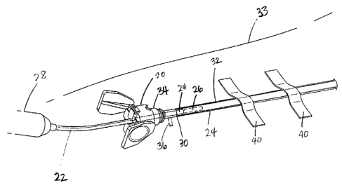
FIG. 1 illustrates a catheter grip 20 in accordance with an embodiment of the
present
invention. The grip 20 is adapted to releasably grip and hold a catheter 22 in
use in a patient's body
for treatment or evaluation, such as mapping, ablation and the like. Once it
is clamped on the
catheter, the grip 20 effectively minimizes, if not prevents, the catheter
from moving or shifting within
the patient's body. As such, the grip 20 frees the hands of the attending
doctor once he has closed
the grip on the catheter. For purposes of the discussion herein, the catheter
22, as with most
conventional catheters, has the elongated catheter body 24 that extends
between a catheter tip
section 26 and a control handle 28. The catheter body 22 and the catheter tip
26 are portions that
generally enter the patient's body, whereas the control handle 28 remains
outside the body.
The catheter grip 20 is adapted for use with an introducer or sheath 30 having
a tubular
needle 32 that is inserted into a patient's vein or artery, typically in a leg
33. Introducers, sheaths are
generally known and can take on many different configurations. Most have a
valve 34 that is provided
at the proximal end of the needle. The valve may or may not have a side port
36 for the introduction of
-3-
WO 2005/123167 CA 02570397 2006-12-14 PCT/US2005/020927
1
a fluid to the entry site of the tubular needle 32. Accordingly, the
introducer or sheath (used
interchangeably herein) is generally used to facilitate the entry of the
catheter tip 26 (not shown) and
body 24 into the vein by providing a prepared portal into the patient's body
through the valve 34 and
the needle 32.
Referring FIGS. 1 and 2, the grip 20 is configured as a cylinder or barrel
which functions in
part as a coupling hub 38 that attaches to the proximal end of the valve 34
before or, more preferably,
after the introducer 30 has already been inserted and secured to the patient
by conventional methods,
such as medical tape and bandages 39. The valve 34 and the hub 38 are
releasably coupled to the
extent that inadvertent detachment is avoided but intentional decoupling is
facilitated. In that regard,
the valve and the hub can be snap-fitted, threaded, latched together and/or
detachably coupled by
other similar methods. In the illustrated embodiment, the valve and hub are
frictionally engaged by
means of a female fitting formed in the proximal end of the valve and a
closely-conforming male fitting
formed in the distal end of the hub. It is understood by one of ordinary skill
in the art that the
configuration, shape and/or size of the hub and the valve can vary. The grip
20 is preferably
constructed of a suitably rigid material (including plastic, steel, synthetic
or natural rubber, and the like,
or combinations thereof) to accomplish its function of holding and maintaining
the catheter in position
in the patient's body.
With the introducer 30 secured to the patient's body and the grip 20 coupled
to the introducer
at its proximal end, the catheter tip 26 and body 24 can be inserted through
the grip and the coupled
introducer for entry into the patient's body further through the needle 32. As
best shown in FIGS. 2-3,
the hub 38 is also configured with a channel 40 that extends between a distal
end 42 and a proximal
end 44, the latter of which has an aperture 46 formed in an end wall 48 that
extends across the
channel. The aperture 46 and the hub 38 are generally concentric about an axis
50 through the
channel 40 and each is configured to permit the passing and generally free
movement of the catheter
tip section 26 and body 24 distally and proximally through the channel 40.
In the illustrated embodiment, the grip 20 includes a pair of grip members 52
situated on a
proximal surface 54 of the wall 48. The grip members 52 are aligned along a
diameter 56 of the
proximal surface 54 and face each other from across the aperture 46. In
accordance with the present
invention, the grip members 52 can move radially inward toward each other to
clamp onto the catheter
body 24 extending through the aperture 46 and the channel 40. To facilitate
this movement, the grip
members 52 travel on a first track 58 formed in the proximal surface 54 along
the diameter 56, which
-4-
WO 2005/123167 CA 02570397 2006-12-14 PCT/US2005/020927
1
is illustrated with a generally vertical orientation. The grip members 52 and
the track 58 are engaged
with each other by means of corresponding male and female fitting portions.
Referring also to FIG. 4,
the disclosed embodiment of the track 58 has a slot 60 with a T-shaped cross-
section 62 which
receives a ridge 64 with a T-shaped cross-section 66 formed in a distal
surface 68 of each grip
member 52. Guided by the track 58, the grip members 52 are slidable inwardly
and outwardly along
the diameter 56.
It is understood that the aperture 46 itself need not be (and is not)
physically affected by
movement of the grip members 52. It is therefore also understood that the
aperture may be
configured at any location along the length of the channel 40 and that the
grip members 52 need not
be in close proximity to nor proximal of the aperture 46. However, because the
aperture 46 can guide
the travel path of the catheter body 24 in the channel, it may be preferable
in most instances that the
grip members 52 and the aperture 46 be configured at least adjacent to each
other along the channel
40. In the illustrated embodiment, the grip members and the aperture are in
close proximity of each
other and the grip members are immediately proximal of the aperture.
Referring to FIGS. 2 and 6, an inner end 70 of each grip member 52 is
configured with a notch
72 so that the pair can have a more secure hold on the catheter body 24
between them. In particular,
the notch 72 provides better conformity between the interfacing inner ends 70
and the circumference
of the catheter body 24. Depending on the size, flexibility and/or elasticity
of the catheter body, the
inner ends (notched or otherwise) may or may not be in contact with each other
when the grip
members 52 are clamped on the catheter body 24. In any case, the grip members
52, having a greater
frictional contact with the catheter body as provided by the notches, minimize
if not prevent
translational or rotational movement in the catheter body once released from
the hands of the doctor.
To that end, surface 74 of the notches 72 may be textured and/or covered with
a friction-inducing
material 76 (not shown). Once closed, the grip 20 is "hands-free" in
minimizing the need for the doctor
to hold the catheter body 24 in position for fear that the catheter may shift
or move out of position.
In accordance with the present invention, the grip members 52 "rest" in a
closed (or grip)
position, as shown in FIGS. 3 and 6, under the bias of an elastic member or
band 78 shown in FIG. 2.
The elastic member sits in a groove 80 configured in an outer section 82 of
each grip member 52.
The elastic member 78 exerts around its circumference a force directed
radially inward such that the
grip members 52 are under a predetermined bias to move toward (if not to make
contact with) each
other and/or remain in the closed position until actively opened by the user.
-5-
WO 2005/123167 CA 02570397 2006-12-14 PCT/US2005/020927
1
To open the grip members 52, the grip has a pair of separator or wedgers 84
that are also
situated on the proximal face 54 but along a diameter 86 that is offset
between about 60-120 degrees,
and more preferably about 90 degrees, from the diameter 56 of the grip members
52. Like the grip
members, the wedgers 84 face each other from across the aperture 46 and can
move toward and
away from each other. In accordance with the present invention, the catheter
body 24 is released by
the grip 20 when the grip members 52 are separated or driven away from each
other, that is, radially
outward, by the wedgers 84, as shown in FIG. 7. To facilitate this action, the
wedgers 84 travel along
a track 88 also formed in the proximal surface 54 along the diameter 86, best
seen in FIG. 5, with a
generally horizontal orientation. The wedgers 84 and the track 88 are engaged
with each other by
similar means of a male and female fitting portion. In the illustrated
embodiment, the track 88 has a
slot 90 with a T-shaped cross-section 92 which receives a ridge 94 with a T-
shaped cross-section 96
formed in a distal surface of each wedger 84. Guided by the track 88, the
wedgers 84 can slide
inwardly and outwardly along the diameter 86 of the surface 54. And, because
the wedgers 84 and
the grip members 52 interact and are interdependent, as described below in
further detail, they have
portions that affect and/or contact each other and are therefore in close
proximity of each other within
the grip.
The wedgers 84, as the name implies, serve to wedge between and drive apart
the grip
members 52 in releasing the latter's hold on the catheter body 24. Inner ends
98 and 100 of the grip
members 52 and the wedgers 84, respectively, are angled or chamfered at their
corners 99 and 101,
for example, at an angle ranging between about 30 and 60 degrees, and
preferably at about 45
degrees, to facilitate this action. The convergence at the inner ends 100 of
the wedgers 84 however is
not to a point so the inner ends 100 will not protrude toward the catheter
body 24 to the extent they
contact or cause interfere with the catheter body 24.
For optimum leverage between the grip members 52 and the wedgers 84, the inner
ends 98
and 100 can be angled at a complementary angle, for example, where the total
of the angles of the
inner ends equals about 90 degrees). However, it is understood by one of
ordinary skill in the art that
the slant or degree of angle of the inner ends may be varied for different
efficiencies of operation. For
example, a more obtuse angle may offer a different feel or tension in the
operation of the grip 20, than
would a more acute angle. Moreover, the angle (which may or may not be
identical between the
wedge members 84 and the grip members 52) may also depend on or relate to the
offset angle
between the tracks 56 and 86.
-6-
WO 2005/123167 CA 02570397 2006-12-14 PCT/US2005/020927
1
In any case, the grip members 52 are moved toward each other for a closed or
grip position
(FIG. 6), and away from each other for a release position (FIG. 7).
Correspondingly, the wedge
members 84 are moved toward each other for a wedge position (FIG. 7), and away
from each other
for a separated position (FIG. 6). In view of the foregoing description, it is
clear that the movements of
the pairs of grip members 52 and wedge members 84 are coordinated and
interdependent in a
manner whereby one pair moves toward each other as the other pair moves away
from each other.
Movement of the wedge members 84 toward each other to release the catheter
body 24 is
actuated primarily by means of a pair of tabs 102 that the user actuates. The
tabs are pivotably
attached to hinges 104 provided on the hub 38 and situated generally on the
diameter 86 in alignment
with the wedgers 84. The hub may be indexed to facilitate this alignment. In
the illustrated
embodiment, the hinges 104 are distal of the surface 54 and the tabs 102
extend slightly proximally
from the hub 38 with their free ends 106 separated by a maximum distance which
decreases to a
minimum distance when the tabs are squeezed together by the user. When
squeezed, the tabs act on
the wedgers 84 through an angled ridge or cam 108 provided on an inner surface
110 of each tab. As
can be seen in FIG. 7, as the free ends 106 approach each other, each cam 108
engages an adjacent
wedger 84 to drive it inwardly toward its mate.
In accordance with the present invention, the tabs 102 are biased away from
each other by
leaf springs 112 (best seen in FIGS. 6 and 7) such that the tabs spring apart
when the user stops
squeezing. The bias of the elastic member 78 around the grip members 52 also
tends to urge the
wedgers 84 to move away from each other. The wedge members 80 therefore "rest"
apart from each
other (at their maximum separation) until they are moved toward each other by
the tabs. It is
understood that the tabs may be biased to spring apart by other means. To that
end, the leaf springs
112 may be connected or be integrated a single piece extending across the
channel 40 to leverage the
tabs 102 against each other so they move in a coordinated manner, that is,
similarly and
coincidentally.
Advantageously, a doctor can use the very hand working the introducer 30 to
actuate the tabs
102, and do so without changing hand position. The grip 20 therefore provides
improved ergonomics
for the doctor, if not a more versatile working environment in which he has
more mobility, or at least
more freedom with his hands once the grip 20 is closed on the catheter body
24.
-7-
CA 02570397 2012-07-09
As mentioned, the grip 20 rests in the closed position, with the grip members
52 being in
contact with each other under the bias of the elastic member 78 and the
wedgers 84 separated and
generally free from compression by the tabs 102 (FIG. 3). By squeezing the
tabs 102, the doctor
opens the grip 20 so that he can pass the catheter tip and body through the
aperture 46 and into the
introducer 30. As long as the tabs 102 are squeezed, the cams 108 press on the
wedgers 84 inwardly
keeping the grip members 52 wedged apart. The catheter body 24 can then be
advanced by rotation
or translation to the grip 20 as needed to reach the target site inside the
patient's body (FIG. 7).
After the target site has been reached and the catheter body 24 is in
position, the doctor
releases the tabs 102 which separate under the force of the leaf spring 112.
Without any compressive
force pushing the wedgers 84, they are forced outwardly by the inwardly-moving
grip members 52
acting under the force of the elastic member 78 which clamps the grip members
52 on the catheter
body 24 (FIG. 6). The notches 72 close around the circumference of the
catheter body and the
friction-inducing surface 74 securely holds the catheter body 24 to resist
sliding or twisting caused by
any torsional or coiled energy stored in the catheter body. To adjust or
reposition the catheter body
24, the doctor re-squeezes the tabs 102 to re-separate the grip members 52.
Indeed, release of the
grip 20 to separate the grip members 52 at any time can be momentary or of a
longer duration as
desired by the doctor.
It is understood by one of ordinary skill in the art that configuration of the
grip and its
components can be varied. For example, the grip can be biased toward the open
position, such that a
band acts to close the wedge members with a leaf spring and/or the tabs
separating the grip
members. Furthermore, the tabs may be take on a different shape or extend from
the hinge at a
different angle.
The preceding description has been presented with reference to presently
preferred
embodiments of the invention. Workers skilled in the art and technology to
which this invention
pertains will appreciate that alterations and changes in the described
structure may be practiced.
Accordingly, the foregoing description should not be read as pertaining only
to the precise
structures described and illustrated in the accompanying drawings, but rather
should be read
consistent with and as support to the following claims.
-8-