Language selection

Search

Patent 2570586 Summary

Third-party information liability

Some of the information on this Web page has been provided by external sources. The Government of Canada is not responsible for the accuracy, reliability or currency of the information supplied by external sources. Users wishing to rely upon this information should consult directly with the source of the information. Content provided by external sources is not subject to official languages, privacy and accessibility requirements.

Claims and Abstract availability

Any discrepancies in the text and image of the Claims and Abstract are due to differing posting times. Text of the Claims and Abstract are posted:

  • At the time the application is open to public inspection;
  • At the time of issue of the patent (grant).
(12) Patent: (11) CA 2570586
(54) English Title: METHOD FOR REPLACING OLD SLEEPERS OF A RAILWAY TRACK BY NEW SLEEPERS
(54) French Title: PROCEDE POUR REMPLACER D'ANCIENNES TRAVERSES D'UNE VOIE DE CHEMIN DE FER PAR DE NOUVELLES TRAVERSES
Status: Deemed expired
Bibliographic Data
(51) International Patent Classification (IPC):
  • E01B 29/06 (2006.01)
(72) Inventors :
  • THEURER, JOSEF (Austria)
  • BRUNNINGER, MANFRED (Austria)
(73) Owners :
  • FRANZ PLASSER BAHNBAUMASCHINEN-INDUSTRIEGESELLSCHAFT MBH (Austria)
(71) Applicants :
  • FRANZ PLASSER BAHNBAUMASCHINEN-INDUSTRIEGESELLSCHAFT MBH (Austria)
(74) Agent: RICHES, MCKENZIE & HERBERT LLP
(74) Associate agent:
(45) Issued: 2013-03-12
(86) PCT Filing Date: 2005-05-18
(87) Open to Public Inspection: 2006-01-26
Examination requested: 2009-12-01
Availability of licence: N/A
(25) Language of filing: English

Patent Cooperation Treaty (PCT): Yes
(86) PCT Filing Number: PCT/EP2005/052284
(87) International Publication Number: WO2006/008202
(85) National Entry: 2006-11-29

(30) Application Priority Data:
Application No. Country/Territory Date
GM 511/2004 Austria 2004-07-19

Abstracts

English Abstract


The aim of the invention is to replace old ties (6) of a railway track (8) by
new ties (11). This aim can be achieved by spreading the two rails (7) apart
from each other. The reception of ballast gravel (26) for producing a recess
of ballast is carried out in a region below of the sleeper head (25) of a
ballast bed (33), which is located adjacent to the region of the old sleepers
(6) along their longitudinal axis. The received ballast gravel is temporarily
stored and, once the new sleepers (11) have been deposited, thrown off for the
purpose of ballasting. In parallel and prior to the deposit of new sleepers
(11), excess ballast gravel (26) is ploughed in the recess of ballast so as to
produce a levelled surface of ballast (27).


French Abstract

L'objectif de l'invention est de déplacer d'anciennes traverses (6) d'une voie de chemin de fer (8) par de nouvelles traverses (11). A cet effet, les deux rails (7) sont écartés l'un de l'autre. La réception de ballasts (26) destinés à produire une cavité pour un lit est réalisée dans une partie tête avant (26) des traverses d'un lit de ballasts placé sur les anciennes traverses (6) dans le sens de la longueur des traverses. Le ballast est ensuite stocké, puis il est retiré en fonction de la mise en place des nouvelles traverses (11) en vue d'un ballastage. Avant la mise en place des nouvelles traverses (11), des ballasts en surplus (26) sont labourés dans la cavité du lit, de manière à produire un palier de voies (27) de ballasts.

Claims

Note: Claims are shown in the official language in which they were submitted.


4
We claim:


1. A method for replacing old ties of a railroad track with new ties
comprising the steps of:
(a) detaching rails from the old ties;
(b) spreading the rails apart from one another laterally;
(c) picking up ballast in a tie pre-head region of a ballast bed
adjoining the old ties in a longitudinal direction of the old ties for
producing a bed depression;
(d) temporarily storing the picked-up ballast;
(e) picking up the old ties;
(f) producing a ballast level while plowing surplus ballast into the bed
depression;
(g) laying down the new ties; and
(h) discharging the stored ballast for ballasting the new ties.

Description

Note: Descriptions are shown in the official language in which they were submitted.


CA 02570586 2012-01-06
F = 1

Method for Replacing Old Sleepers of a Railway Track by New Sleepers
The invention relates to a method for replacing old sleepers of a track by new
sleepers, wherein rails which have been detached from the old sleepers are
spread apart laterally and a ballast formation is created before laying down
the
new sleepers.

Machines of this type for renewing the sleepers and/or the rails of a track
are
known, for example, from EP 1 195 468 Al or US 5 664 498.

The object of the present invention lies in providing a method of the
specified
kind with which a simplified exchange of sleepers is possible.

Accordingly, in one aspect the present invention resides in a method for
replacing
old ties of a railroad track with new ties comprising the steps of detaching
rails
from the old ties; spreading the rails apart from one another laterally;
picking
up ballast in a tie pre-head region of a ballast bed adjoining the old ties in
a
longitudinal direction of the old ties for producing a bed depression;
temporarily
storing the picked-up ballast; picking up the old ties; producing a ballast
level
while plowing surplus ballast into the bed depression; laying down the new
ties;
and discharging the stored ballast for ballasting the new ties.

Owing to the formation of a bed recess, it is possible to carry out in a
structurally
very simple manner a removal of ballast situated above the ballast formation.
Furthermore, it is possible thereby to reduce the distance between the two
devices for sleeper removal and sleeper laying and thus also the length of the
machine frame as required for bridging the construction gap.

Additional advantages of the invention become apparent from the drawing.

The invention will be described in more detail below with reference to
embodiments
represented in the drawing in which

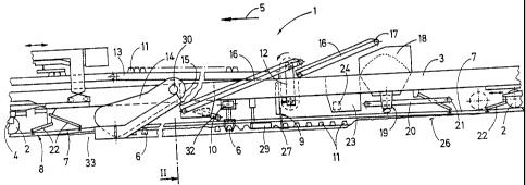
Fig. 1 shows a side view of a machine for exchanging damaged sleepers, and
Fig. 2 shows a simplified cross-section of a ballast bed.

A machine 1 comprises a machine frame 3, supported at the ends on on-track
undercarriages 2 during working operations, and is mobile by means of a motive


CA 02570586 2006-11-29
2

drive 4 in a working direction 5 on a track 8 formed by old sleepers 6, or new
sleepers 11, and rails 7.

Approximately centrally between the two on-track undercarriages 2 placed at
the
ends, a device 10 for picking up the old sleepers 6 as well a device 9 for
laying
down the new sleepers 11 are provided. Said new sleepers 11 are received by a
vertical conveyor 12 from a conveyor belt 13 and placed on a ballast formation
27 of a ballast bed 33. Located between the two devices 9 and 10 is a ballast
plough 29 which is vertically adjustable by drives and V-shaped when seen in
top view.

A vertically and transversely adjustable endless shoulder chain 14 is
connected
to the machine frame 3 in front of the device 10 for picking up the old
sleepers 6,
with regard to the working direction 5. The shoulder chain 14 is rotatable by
means of a drive 30 in a plane which extends perpendicularly to the plane of
the
ballast formation 27 and in the longitudinal direction of the machine.

Associated with a discharge opening 15 of the shoulder chain 14 is a conveyor
belt 16 having a discharge end 17. The latter is situated above a ballast
hopper
18 - positioned between the rear on-track undercarriage 2 and the device 9 for
laying down the new sleepers 11 - which comprises a discharge arrangement 19.
The latter is in the shape of a discharge conveyor belt 20, having a discharge
end 21, which is fastened to the ballast hopper 18 for rotation about a
vertical
axis. Vertically and transversely adjustable rail guides 22 are located
between
the two on-track undercarriages 2 arranged at the ends. A control device 24 is
associated with a work cabin 23.

The method of renewing sleepers will be described in more detail below.

At the start of working operations, the two rails 7 detached from the old
sleepers
6 are spread apart from one another, with the aid of the rail guides 22, to a
distance exceeding the sleeper length. With the machine 1 advancing in the
working direction 5, ballast 26 present in a sleeper end region 25 (see Fig.
2) is
picked up by lowering the shoulder chain 14 and discharged via the conveyor


CA 02570586 2006-11-29
3
belt 16 into the ballast hopper 18. In the process, a bed recess 31 is created
by
the picking-up of ballast.

By means of the device 10 following behind, the old sleepers 6 are gripped and
laid upon a conveyor belt 32 for being transported away. Thereafter, surplus
ballast 26 is ploughed or shifted by means of the ballast plough 29 in the
direction towards the bed recess 31, thus creating the ballast formation 27.
Immediately following this, the new sleepers 11 are laid down by means of the
device 9. In further sequence, the spread-apart rails 7 are brought together
again to gauge width and laid upon the new sleepers 11. Immediately in front
of
the rear on-track undercarriage 2, stored ballast 26 is discharged via the
discharge conveyor belt 20 in order to fill up cribs located between the new
sleepers 11.

Within the scope of the invention, it is possible to either employ two
shoulder
chains 14, lying opposite one another in the transverse direction of the
machine,
or also only one shoulder chain 14.

Representative Drawing
A single figure which represents the drawing illustrating the invention.
Administrative Status

For a clearer understanding of the status of the application/patent presented on this page, the site Disclaimer , as well as the definitions for Patent , Administrative Status , Maintenance Fee  and Payment History  should be consulted.

Administrative Status

Title Date
Forecasted Issue Date 2013-03-12
(86) PCT Filing Date 2005-05-18
(87) PCT Publication Date 2006-01-26
(85) National Entry 2006-11-29
Examination Requested 2009-12-01
Correction of Dead Application 2010-03-15
(45) Issued 2013-03-12
Deemed Expired 2020-08-31

Abandonment History

There is no abandonment history.

Payment History

Fee Type Anniversary Year Due Date Amount Paid Paid Date
Registration of a document - section 124 $100.00 2006-11-29
Application Fee $400.00 2006-11-29
Maintenance Fee - Application - New Act 2 2007-05-18 $100.00 2006-11-29
Maintenance Fee - Application - New Act 3 2008-05-20 $100.00 2008-04-17
Maintenance Fee - Application - New Act 4 2009-05-19 $100.00 2009-04-17
Request for Examination $800.00 2009-12-01
Maintenance Fee - Application - New Act 5 2010-05-18 $200.00 2010-04-16
Maintenance Fee - Application - New Act 6 2011-05-18 $200.00 2011-04-18
Maintenance Fee - Application - New Act 7 2012-05-18 $200.00 2012-04-17
Final Fee $300.00 2012-11-09
Maintenance Fee - Patent - New Act 8 2013-05-21 $200.00 2013-04-26
Maintenance Fee - Patent - New Act 9 2014-05-20 $200.00 2014-04-23
Maintenance Fee - Patent - New Act 10 2015-05-19 $250.00 2015-04-27
Maintenance Fee - Patent - New Act 11 2016-05-18 $250.00 2016-04-15
Maintenance Fee - Patent - New Act 12 2017-05-18 $250.00 2017-04-19
Maintenance Fee - Patent - New Act 13 2018-05-18 $250.00 2018-04-16
Maintenance Fee - Patent - New Act 14 2019-05-21 $250.00 2019-04-09
Owners on Record

Note: Records showing the ownership history in alphabetical order.

Current Owners on Record
FRANZ PLASSER BAHNBAUMASCHINEN-INDUSTRIEGESELLSCHAFT MBH
Past Owners on Record
BRUNNINGER, MANFRED
THEURER, JOSEF
Past Owners that do not appear in the "Owners on Record" listing will appear in other documentation within the application.
Documents

To view selected files, please enter reCAPTCHA code :


To view images, click a link in the Document Description column. To download the documents, select one or more checkboxes in the first column and then click the "Download Selected in PDF format (Zip Archive)" or the "Download Selected as Single PDF" button.

List of published and non-published patent-specific documents on the CPD .

If you have any difficulty accessing content, you can call the Client Service Centre at 1-866-997-1936 or send them an e-mail at CIPO Client Service Centre.


Document
Description 
Date
(yyyy-mm-dd) 
Number of pages   Size of Image (KB) 
Drawings 2006-11-29 1 27
Claims 2006-11-29 1 19
Description 2006-11-29 3 120
Representative Drawing 2007-02-15 1 15
Cover Page 2007-02-16 1 51
Description 2012-01-06 3 129
Claims 2012-01-06 1 15
Representative Drawing 2013-02-12 1 16
Cover Page 2013-02-12 1 51
Abstract 2013-03-11 1 82
Assignment 2006-11-29 4 130
PCT 2006-11-29 1 82
Correspondence 2007-02-13 1 28
Correspondence 2008-02-08 2 37
Correspondence 2008-03-19 2 71
Fees 2008-04-17 1 53
Fees 2009-04-17 1 53
Prosecution-Amendment 2009-12-01 1 51
Correspondence 2010-02-16 1 12
Prosecution-Amendment 2011-08-31 2 74
Fees 2010-04-16 1 53
Fees 2011-04-18 1 52
Prosecution-Amendment 2012-01-06 5 167
Correspondence 2012-11-09 1 57
Fees 2012-04-17 1 54