Note: Descriptions are shown in the official language in which they were submitted.
CA 02571234 2006-12-08
WO 2006/009614 PCT/US2005/019863
MECHANICAL PIPE COUPLING
DERIVED FROM A STANDARD FITTING
Related Application
This application is a continuation-in-part of U.S.
Application No. 10/123,607, filed April 16, 2002, which is a
continuation-in-part of U.S. Application No. 10/007,951,
filed December 3, 2001, which is based on and claims
priority of U.S. Provisional Application No. 60/262,820,
filed January 19, 2001.
Field of the Invention
This invention relates to couplings for pipes and
especially to mechanical couplings derived from standard
fittings which effect a strong, reliable joint with a fluid-
tight seal without the need for brazing or soldering.
Background of the Invention
The construction of piping networks requires couplings
that can form fluid-tight joints between pipe ends which can
withstand external mechanical forces, as well as internal
fluid pressure and reliably maintain the integrity of the
joint. Many forms of joints are known, such as brazed or
soldered joints, threaded joints, welded joints and joints
effected by mechanical means'.
For example, copper tubing, which is used extensively
throughout the world to provide water service in homes,
businesses and industry, is typically joined by means of
couplings which are soldered to the pipe ends to effect a
connection.
1
CA 02571234 2006-12-08
WO 2006/009614 PCT/US2005/019863
The use of copper tubing for piping networks is so
widespread that standard tubing sizes have been established
in various countries. For example, in the U.S., there is
the ASTM Standard; in Germany, the DIN Standard; and in the
United Kingdom, the British Standard (BS). Chart Z below
shows a portion of the range of nominal diameters of the
various standard copper tubes listed above.
Chart 1
Standard Outer Copper Tube Outer Diameters
ASTM DIN BS
1/2" 15mm 15mm
3/4U 22mm 22mm
1" 28mm 28mm
1.25" 35mm 35mm
1.5" 42mm 42mm
2" 54mm 54mm
Naturally, there are standard pipe fittings such as
elbows (45 and 90 ), tees and straight segments matched for
use with the standard tube diameters. These standard
fittings are defined in the U.S. by ASME Standard B16.22a-
1998, Addenda to ASME B16.22-1995 entitled "Wrought Copper
and Copper Alloy Solder Joint Pressure Fittings" dated 1998
and hereby incorporated by reference. The standard fittings
have open ends with inner diameters sized to accept the
outer diameter of a particular standard tube in mating
contact for effecting a soldered joint.
In addition to the standard fittings described above,
other components, such as valves, strainers, adapters, flow
measurement devices and other components which may be found
in a pipe network, will have a coupling which is compatible
with the standard pipe, and it is understood that the term
"coupling", when used herein, is not limited to a standard
2
CA 02571234 2006-12-08
WO 2006/009614 PCT/1JS2005/019863
elbow, tee or other fitting but includes the open end of any
component useable in a piping network which serves to couple
the component to the pipe end.
A soldered joint is effected between a standard
diameter tube end and its associated standard fitting by
first cleaning the surfaces to be joined, typically with an
abrasive such as a wire brush or steel wool, to remove any
contaminants and the oxide layer which forms on the
surfaces. Next, the cleaned surfaces are coated with a flux
material, usually an acid flux, which further disrupts the
oxide layer (especially when heated) and permits metal to
metal contact between the fitting, the pipe end and the
solder. The pipe end is next mated with the fitting thereby
bringing the cleaned, flux coated surfaces into contact.
The fitting and pipe end are then heated to the melting
temperature of the solder, and the solder is applied to the
interface between the tube and the fitting. The solder
melts, flows between the surfaces of the pipe end and the
fitting via capillary action and upon cooling and
solidifying forms the solder joint. Excess flux is removed
from the outer surfaces to prevent further acid etching of
the pipe near the joint.
While the soldered joint provides a strong, fluid-tight
connection between pipe end and fitting, it has several
disadvantages. Many steps are required to make the soldered
joint, thus, it is a time consuming and labor intensive
operation. Some skill is required to obtain a quality,
fluid-tight joint. Furthermore, the solder often contains
lead, and the flux, when heated, can give off noxious fumes,
thus, exposing the worker to hazardous substances which can
adversely affect health over time. The joint is typically
heated with an open gas flame which can pose a fire hazard,
as well as a personal burn hazard.
3
CA 02571234 2006-12-08
WO 2006/009614 PCT/US2005/019863
To overcome these disadvantages, many attempts have
been made to create mechanical couplings which do not
require solder or flame to effect a strong, fluid-tight
joint. Such mechanical couplings often use an over-sized
opening accommodating an 0-ring for sealing purposes and an
annular retainer interposed between the outer diameter of
the pipe end and the inner diameter of the coupling to
mechanically hold the parts together. The retainer often
has radially extending teeth which dig into the facing
surfaces of the coupling and the pipe end to resist
extraction of the pipe end from the coupling after
erigagement.
While these mechanical couplings avoid the above
identified problems associated with soldered joints, they
can suffer from one or more of the following disadvantages.
To be effective, the retainer requires sufficient space
within the coupling. Thus, the couplings tend to be
oversized relatively to the pipes they are intended to
receive, and if existing standard couplings are to be
adapted for use with such a mechanical system, it is usually
necessary to adapt a larger size standard fitting to a
smaller size standard pipe. This is more expensive than
adapting the standard fitting appropriate to the standard
pipe in what is known as a size-on-size" fitting. For
example, a standard 3/4 inch pipe fitting may be used to
couple a 1/2 inch standard copper pipe in a mechanical
system (not "size-on-size"). Furthermore, the retainer may
not provide adequate pull-out strength, and the pipe end
could be inadvertently separated from the coupling, for
example, during a pressure spike within the pipe, caused by
a sudden closing of a valve (the "water hammer effect")
which places the joint under increased tension.
4
CA 02571234 2006-12-08
WO 2006/009614 PCT/US2005/019863
The retainer also does not help keep the pipe end
coaxial with the coupling upon insertion, allowing the pipe
end to tip and deform the retainer and gouge the inside
surface of the coupling or an elastomeric seal, such as an
0-ring. In such a mechanical joint, there is furthermore
little or no resistance to axial rotation of the pipe
relatively to the coupling (i.e., relative rotation of the
pipe and coupling about the longitudinal axis of the pipe).
Thus, valves or other items mounted on the pipe will tend
to rotate. Mechanical joints with retainers also tend to
have little resistance to bending, allowing the pipe too
much angular free play and permitting the pipe to "walk" out
of the joint under repeated reversed bending loads.
Excessive free play also tends to disengage the teeth on one
side of the retainer and deform the teeth on the other side,
weakening the joint. Furthermore, use of an enlarged
section to accommodate the retainer,may cause energy loss
impeding fluid flow if the fluid is forced to flow into a
coupling having a larger cross-sectional area. In general,
when mechanical couplings are designed to overcome the
aforementioned inherent disadvantages, they tend to suffer
from a high part count, making them relatively complex and
expensive.
There is clearly a need for a mechanical pipe coupling
which avoids the disadvantages of both soldered pipe
fittings, as well as prior art mechanical fittings described
above, and which can be derived from existing standard
fittings and used with pipes appropriate to the standard
fitting in a"size-on-size" association rather than using a
larger size fitting to couple smaller diameter pipes
together.
5
CA 02571234 2006-12-08
WO 2006/009614 PCT/US2005/019863
Summary of the Invention
The invention concerns a pipe coupling housing having a
socket with an inner diamete=r sized to receive a pipe and an
outer diameter. The pipe coupling housing comprises an
expanded region positioned adjacent to one end of the
socket. The expanded region has an inner diameter and an
outer diameter larger than the inner and outer diameters of
the socket respectively. The expanded region also has an
end defining an opening for receiving the pipe. A first
shoulder is positioned between the socket and the expanded
region. A second shoulder is positioned intermediate
between the first shoulder and the opening. A third
shoulder is positioned adjacent to the opening, and a lip is
positioned at the opening in spaced relation to the third
shoulder. The lip projects substantially radially inwardly.
The functions of the various features of the housing are
described below in the context of the pipe coupling.
The pipe coupling is sealingly engageable with a pipe. The
pipe coupling comprises a housing as described above and
further includes a sealing member positioned in the expanded
region to effect a seal between the pipe coupling and the
pipe. The sealing member engages the first shoulder which
prevents the sealing member from moving further into the
coupling housing when a pipe is received in the socket. A
first support washer is positioned in the expanded region
adjacent to the sealing member. The first support washer
engages the second shoulder which acts as a stop preventing
further motion of the first support washer toward the
sealing member. A retainer is positioned within the
expanded region adjacent to the first support washer. The
retainer has a circumferential rim and a plurality of teeth
projecting inwardly therefrom. A second support washer is
positioned within the expanded region between the third
shoulder and the opening. The second support washer engages
6
CA 02571234 2006-12-08
WO 2006/009614 PCT/US2005/019863
the third shoulder and remains in spaced apart relation away
from the first support washer over a distance at least equal
to the width of the retainer rim. A lip is positioned at
the opening in spaced relation to the third shoulder. The
lip projects substantially radially inwardly to engage the
second support washer and retain it between the third
shoulder and the opening.
The invention also includes a method of manufacturing a pipe
coupling housing. The method comprises the steps of:
(A) providing or forming a fitting having a socket;
(B) expanding a portion of the socket into an expanded
region having a larger inner diameter than the socket, the
first expanded region defining an opening;
(C) forming a first shoulder between the socket and the
expanded region;
(D) forming a second shoulder between the first shoulder and
the opening; and
(E) forming a third shoulder between the second shoulder and
the opening.
The coupling may be assembled using the housing by inserting
into the expanded region the sealing member, the retainer
and the support washers and then forming the lip that
captures these internal components within the expanded
region.
Preferably, the fitting provided is one that is readily
available and manufactured according to a standard, such as
ASME Standard B16.22a-1998. This standard includes fittings
having sockets sized to receive copper pipe having a nominal
diameter between 1/2 inch and 2 inches inclusive. Other
standards may also be considered, for example, standards
wherein the socket is sized to receive copper pipe having a
nominal diameter between 15 mm and 54 mm inclusive.
7
CA 02571234 2006-12-08
WO 2006/009614 PCT/1JS2005/019863
Brief Description of the Drawincrs
Figure 1 is a partial longitudinal sectional view of a pipe
coupling housing according to the.invention;
Figure lA is a partial longitudinal sectional view of an
alternate embodiment of a pipe coupling housing according to
the invention;
Figure 2 is a longitudinal sectional view of a pipe coupling
according to the invention; and
Figure 3 is an exploded perspective view of a pipe coupling
in the form of an elbow fitting according to the invention.
Detailed Description of the Preferred Embodiment
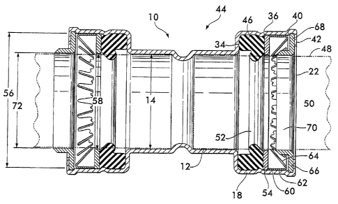
Figure 1 shows a pipe coupling housing 10 according to the
invention. Housing 10 is preferably formed from a readily
available standard pipe fitting and has a socket 12 with an
inner diameter 14 sized to receive a pipe. Socket 12 also
has an outer diameter 16. An expanded region 18 is
positioned adjacent to one end of the socket 12. The
expanded region 18 has an end 20 opposite the socket 12 that
defines an opening 22 for receiving the pipe. A pipe stop
24 is positioned adjacent to the opposite end of socket 12.
Pipe stop 24 is formed by a surface 26 that projects
substantially radially inwardly to engage the pipe received
within the socket. The stop 24 may extend substantially
continuously around the circumference of the housing as
shown in Figure 1, or it may comprise one or more discrete
surfaces 28 as illustrated in Figure lA.
With reference again to Figure 1, the expanded region 18 has
an inner diameter 30 and an outer diameter 32, both of which
are larger, respectively, than the inner and outer diameters
14 and 16 of socket 12. A first shoulder 34 is positioned
8
CA 02571234 2006-12-08
WO 2006/009614 PCT/US2005/019863
between the socket 12 and the expanded region 18. A second
shoulder 36 is positioned within the expanded region 18
intermediate between the first shoulder 34 and the opening
22. Preferably, second shoulder 36 is formed by a dimple 38
projecting substantially radially inwardly of the housing
10. Dimple 38 may extend substantially continuously around
the expanded region 18 or it may be discontinuous as shown
in Figure 1A. Figure 1 shows a third shoulder 40 positioned
adjacent to opening 22, and a lip 42, positioned at the
opening 22 in spaced relation to the third shoulder. Lip 42
projects radially inwardly of the coupling 10. The
functions of the various aforementioned features of the
housing 10 are described below in the context of the pipe
coupling and its components.
Figure 2 is a longitudinal sectional view of a pipe coupling
44 according to the invention. Coupling 44 comprises
housing 10 and further includes a sealing member 46
positioned within expanded region 18. Sealing member 46
engages first shoulder 34 and effects a seal between the
outer surface 48 of a pipe 50 (shpwn in broken line received
within the coupling) and the pipe coupling housing.
Engagement between the sealing member 46 and the first
shoulder 34 prevents the sealing member from being dislodged
from the expanded region 18 upon insertion of pipe 50 into
the socket 12. Preferably, sealing member 46 is a pressure
responsive seal having a lobe or gland 52 that is
pressurized by the fluid within the pipe 50, the pressure
further forcing the gland 52 against the pipe outer surface
48 thereby effecting a fluid tight seal. Pressure
responsive sealing members are advantageous because they
provide a fluid tight seal without the need for significant
interference between the sealing member 46 and the pipe 50,
thus lowering the insertion force necessary to engage the
pipe 50 with the coupling 44.
9
CA 02571234 2006-12-08
WO 2006/009614 PCT/US2005/019863
A first support washer 54 is positioned within the expanded
region adjacent to the sealing member 46. First support
washer 54 preferably engages or is engageable with the
sealing member 46 to prevent its extrusion outwardly toward
the opening 22 of coupling housing 10 when it is subjected
to high fluid pressure within the pipe 50. The first
support washer 54 has an outer diameter 56 that allows it to
engage the second shoulder 36, thus fixing the washer's
position within the expanded region 18. Preferably, the
first support washer 54 also has an inner diameter 58 that
is substantially equal to the socket inner diameter 14,
allowing the first support washer to engage and support the
pipe 50 received within the socket 12. Preferably, the
first support washer is made from stainless steel to prevent
corrosion although beryllium copper alloys, as well as high
strength engineering plastics are also feasible. It is also
feasible to attach seal 46 to support washer 54.
A retainer 60 is positioned within the expanded region 18
adjacent to the first support washer 54. Retainer 60
preferably comprises a circumferential rim 62 sized to fit
substantially coaxially within the expanded region 18, and a
plurality of teeth 64 projecting from the rim 62.
Preferably, teeth 64 extend angularly inwardly toward the
socket 12. The teeth 64 are designed to engage the outer
surface 48 of pipe 50 when it is received within the housing
10. The angular orientation of the teeth 64 cause them to
be "self jamming" in that they dig into the pipe surface 48
in response to outward motion (caused by internal pressure
or external loads) to prevent withdrawal of the pipe from
the coupling 44. This is particularly advantageous for
plain end pipe as shown in Figure 2. Engagement of the
teeth 64 with the pipe 50 may be enhanced by the
incorporation of circumferential grooves 78 around the pipe
CA 02571234 2006-12-08
WO 2006/009614 PCT/US2005/019863
50 as shown in Figure 3. The grooves provide purchase for
the teeth, increasing their ability to prevent withdrawal of
the pipe from the coupling. Preferably, the retainer is
made from stainless steel to prevent corrosion although
beryllium copper alloys are also feasible. Engineering
plastics are also feasible and may be used with plastic pipe
and plastic fittings.
As shown in Figure 2, a second support washer 66 is
positioned within the expanded region 18. Second support
washer 66 engages the third shoulder 40 which keeps the
second support washer in spaced apart relation away from the
first support washer 54 over a distance at least equal to
the width of rim 62. It is found advantageous to maintain
this separation between the support washers so as to avoid
imposing contact forces between the second support washer 66
and the teeth 64 upon assembly of the coupling. Such
contact forces operate to deflect the teeth 64 and relieve
the preload between them and the pipe surface 48. Relief of
the preload, if allowed to occur, inhibits the ability of
the retainer to prevent withdrawal of the pipe 50 from the
coupling 44, thus, reducing the maximum pressure at which
the coupling maintains a fluid tight seal.
It is advantageous to construct the second support washer 66
from a circumferential flange 68 and a collar 70.
Circumferential flange 68 is sized to engage the third
shoulder 40 while the collar 70 is oriented transversely to
the flange, preferably co-axially with the socket 12.
Collar 70 preferably has an inner diameter 72 substantially
equal to the inner diameter 14 of the socket 12 and can
thereby provide alignment and support to the pipe 50 upon
engagement with the coupling 44. As shown on the right side
of Figure 2, collar 70 may project inwardly to engage and
support teeth 64 when they are deflected to the right by
motion of pipe 50 to the right. Support of the teeth by the
11
CA 02571234 2006-12-08
WO 2006/009614 PCT/1JS2005/019863
collar increases the force required to withdraw the pipe
from the coupling, thus increasing the maximum pressure
which the coupling can withstand. As shown on the left side
of Figure 2, collar 70 may also project outwardly from the
coupling to increase the total distance over which pipe 50
is directly supported by the coupling 44, thus providing
greater bending stiffness to the joint formed between the
coupling and the pipe. Preferably, the second support
washer is made from stainless steel to prevent corrosion
although beryllium copper alloys, as well as high strength
engineering plastics are also feasible.
Lip 42 surrounds and defines opening 22, the lip being
positioned in spaced apart relation with the third shoulder
40 so that the second support washer 66 may be captured
between the lip and the third shoulder. Lip 42 projects
substantially radially inwardly to engage and capture the
second support washer 66. Preferably lip 42 comprises a
portion of expanded region 18 that is turned inwardly after
the sealing member 46, first support washer 54, retainer 60
and second support washer 66 are positioned within the
expanded region.
Figure 3 shows an exploded view of a coupling 44 according
to the invention in the form of an elbow fitting 76, it
being understood that the coupling may take any of various
practical forms including Tee fittings, reducers and may
also be used on components such at valves, strainers and the
like to couple the components to pipes as well as pipes to
pipes. As described above, elbow fitting 76 is preferably
formed from a standard fitting, for example ASME Standard
B16.22a-1998. The expanded region 18 is adjacent to the
socket 12, the first shoulder 34 is engaged by the sealing
member 46, the first support washer 54 engages the second
shoulder 36, the retainer 60 is positioned adjacent to the
12
CA 02571234 2006-12-08
WO 2006/009614 PCT/US2005/019863
first support washer 54, the second support washer 66
engages the third shoulder 40 and is kept in spaced apart
relation from the first support washer 54 over a distance at
least equal to the width of the rim 62. Lip 42, shown in
broken line, extends substantially radially inwardly to
capture the aforementioned components within the expanded
region 18. Lip 42 defines opening 22 that receives pipe 50,
the pipe in this example having the aforementioned grooves
78 to provide purchase to teeth 64 of the retainer.
In manufacturing the coupling according to the invention, it
is preferred to begin with a commonly available standard
fitting such as those made according to ASME Standard
B16.22a-1998 for wrought copper fittings. These fittings
are especially appropriate for use to couple to pipes having
a nominal diameter between 1/2 inch and 2 inches inclusive.
Other standards are also available, for example British or
German DIN standards that specify fittings appropriate for
copper pipe having a nominal diameter between 15 mm and 54
mm inclusive. It is also feasible to form the fitting by
various techniques. Cast and forged fittings are preferred
for certain types of valves and other fittings, and such
castings or forgings are compatible with the coupling
housing design and internal components as described
previously.
The method of manufacture according to the invention
includes the steps of providing or forming the fitting,
preferably a fitting manufactured to comply with a standard
such as ASME Standard B16.22a-1998, and then expanding a
portion of the socket to form the expanded region. The
expansion is preferably accomplished by die forming the
existing fitting although other techniques, such as hydro-
forming and spinning are also feasible.
13
CA 02571234 2006-12-08
WO 2006/009614 PCT/US2005/019863
The aforementioned die forming techniques may also be used
to form the first shoulder between the socket and the
expanded region as well as the second shoulder between the
first shoulder and the opening and the third shoulder
between the second shoulder and the opening. Once all of
the shoulders have been formed the sealing member, the first
support washer, the retainer and the second support washer
are inserted into the expanded region and the lip is formed,
preferably by rolling the free edge of the expanded region
over so that the lip extends substantially radially inwardly
of the coupling.
Couplings according to the invention provide a
mechanical pipe coupling which can form a reliable fluid-
tight joint without the hazards associated with brazing,
welding or soldering while taking advantage of existing
standard fittings in a size-on-size relationship with
standard pipe to achieve significant economical advantage.
14