Note: Descriptions are shown in the official language in which they were submitted.
CA 02571780 2011-01-18
VENTED DISPENSER
BACKGROUND OF THE INVENTION
The field of the invention is dispensers for chemical concentrates, and
particularly
the dispensing of chemical concentrates, from a container, which can cause an
increase in
pressure in the container.
Dispensers of the type concerned within this invention are disclosed in U.S.
Patent
No. 6,708,901, which may be referred to for further details. The dispensing
apparatus
disclosed in this patent can control the flow of carrier liquid and chemical
product in a
precise and controlled manner. However, there are instances where the chemical
product
which is stored in the container from which the chemical product is dispensed
can cause
an increase in pressure. If the contents of the container are not vented, a
problem can
arise.
1
CA 02571780 2006-12-21
WO 2006/007035 PCT/US2005/015190
Vented type dispensers are disclosed in U.S. Patents No. 1,638,550 and No.
3,157,360. Venting systems for containers are described in U.S. Patents No.
4,993,602
and No. 6,196,409.
The prior art does not provide a venting of excess pressure from a container
which
is employed in conjunction with a dispenser employing an eductor. Neither does
the
prior art provide such a venting of excess pressure from a dispenser which
includes an air
vent passage that is closed when the dispenser is not in operation.
SUMMARY OF THE INVENTION
The present invention provides a dispenser for dispensing different quantities
of
chemical concentrate into a stream of fluid from a concentrate container at
different flow
rates. It includes a body member having a through bore with an inlet end
adapted to be
connected to a source of pressurized liquid at one end and an outlet at the
opposite end.
A product passage and a vent passage communicate with the through bore. An
eductor is
mounted in the through bore. A cap member is connected to the body member and
a vent
member is connected to the cap member.
In a preferred embodiment, the vent member is gas pervious and liquid
impervious.
In one aspect, the vent passage is constructed and arranged to be in a closed
position when the product passage is closed.
In another aspect, the eductor is both slideable and rotatable, and the
dispenser
includes a trigger member constructed and arranged to slide the eductor and
open the vent
passage and includes 'a seal constructed and arranged to seal both the product
passage and
the vent passage.
In another preferred embodiment, the eductor is composed of first and second
parts, only one of which is rotatable and the first part of the eductor is
rotatable and
extends from the body member.
2
CA 02571780 2006-12-21
WO 2006/007035 PCT/US2005/015190
In yet another preferred embodiment, a valve member is positioned in the
through
bore for regulating the flow or water through the through bore and the
eductor.
In yet another aspect, the dispenser includes a trigger member connected to
the
body member and eductor to cause slideable movement of the eductor with the
trigger
member including a latching mechanism and an essentially flat thumb engaging
portion.
A general object of certain embodiments of the invention is to provide a
dispensing apparatus which can dispense a wide variety of chemical products.
Another object of certain embodiments of the invention is to provide a
dispenser
in conjunction with a container wherein the container and the dispensing
apparatus are
vented.
Still another object of certain embodiments of the invention is to provide a
dispenser which is connected to a container wherein excess pressure in the
container is
vented.
Yet another object of certain embodiments of the invention is to provide a
combined dispenser and container which is economical to produce and is
dispensable as
well as recyclable.
Yet another object of certain embodiments of the invention is to provide a
dispenser which can effect a mixing of chemical and concentrate into a stream
of water at
different concentrations and dispense the mixed concentrate at controlled flow
rates.
BRIEF DESCRIPTION OF THE DRAWINGS
FIG. 1 is a perspective view of the dispenser of this invention in conjunction
with
a container;
FIG. 2 is a view in side elevation of the dispenser shown in FIG. 1;
FIG. 3 is a cross-sectional view of the dispenser shown in FIG. 1 illustrating
a
vent;
3
CA 02571780 2010-06-29
FIG. 4 is a bottom view of the dispenser shown in FIG. 1 illustrating the vent
as
well as an air passage and the passage for a dip tube;
FIG. 5 is an exploded view of the component parts of the dispenser,
FIG. 6 is a cross-sectional view of the dispenser in a closed position;
FIG. 7 is a view similar to FIG. 4 showing the dispenser in a low flow
condition;
FIG. 8 is a view similar to FIG. 4 showing the dispenser in a high flow
condition;
FIG. 9 is a cross-sectional view illustrating an indexing of an eductor in the
dispenser;
FIG. 10 is a fragmentary view of the dispenser housing illustrating the
eductor
contact surfaces for limiting the movement thereof;
FIG. 11 is a cross-sectional view of the dilution adjustment member utilized
in the
dispenser; and
FIG. 12 is a cross-sectional view of a component of a flow control device
employed in the dispenser.
DESCRIPTION OF TBE PREFERRED EMBODMENTS
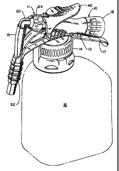
Referring to FIGS. I and 2, the dispenser generally 10 has a body member 12
with a container connector 14 for connection to a container or bottle 16. A
prefen-ed
connector system is more fully described in commonly owned Canadian patent
application Serial No. 2,460,732 laid open May 22, 2003 which may be referred
to for
further details. At one end of the body member 12 is a hose attachment 18 for
supplying
pressurized water to the dispenser. A handle 17 is provided below attachment
18. At the
other end there is the spout 22 and a nozzle 20 for dispensing a mixed
chemical solution
A flexible tube 15 extends between nozzle 20 and spout 22.
4
CA 02571780 2010-06-29
As seen in FIGS. 3 and 4, there is a nipple 6 which provides connection to a
dip
tube 19 and an air or vent passage 25. The purpose of these is described
later. There is
also a vent member 7 which is of the liquid impervious but gas pervious type.
It is
available from W.L. Gore & Associates GmbH. The purpose is to allow gas to
escape
from container 16 when it is filled with a disinfectant cleaner which contains
hydrogen
peroxide. Oxygen gas can evolve and cause a problem with undesired expansion
of the
container 16. In the instance where chlorine bleach is employed, the evolved
gas would
be chlorine. Vent member 7 with the micro-porous member 9 is press fitted into
the body
member 12 by means of collar 5. Vent passageway 7a exits to the outside of
body
member 12 between the ribs 35 as indicated in FIG. 1.
As stated previously, the container connector 14 for connecting the body
member
12 to the container 16 is more fully described in Canadian patent application
Serial No.
2,460,732. It includes a fastening member or cap 68 with threads 4 for
connection to the
threads 2 on the bottle neck 1. A gasket 67 is preferably placed between the
top of the
bottle neck 1 and he body member 12.
Referring to FIGS. 5 and 6, the dispenser 10 includes an eduetor generally I1
composed of the first or outer eductor part 24 with a diverging passage 24a
and an inner
second eductor part 26 with a converging passage 26a. They are slideably
connected in
body member 12 with seals 52 and 56 providing a fluid tight contact. A valve
assembly
28 for controlling the flow of water through the dispenser 10 is also
slideably housed in
body member 12 and is in contact with eductor part 26. The hose attachment 18
is
rotatably connected to body member 12 by the snap fitment 34. A back flow
preventer
30 is positioned in hose attachment 18 and has a seal 32 for contact with body
member
12. At the opposite end of body member 12, the nozzle 20 is attached to
eductor part 24.
An annular groove 36 is provided in the eductor part 24 and accommodates a
head
portion 38 of the trigger 40 with Rang portions such as shown at 42 on the
trigger 40
having shafts (not shown) for extending into bores such as 44. A latch member
46
extends upwardly from the member 12 for fitment through the passage 48 of the
trigger
40.
CA 02571780 2006-12-21
WO 2006/007035 PCT/US2005/015190
A dilution adjustment member 50 is connected to the eductor part 24 by means
of
the splines 47. This is shown in FIG. 11. It has L-shaped passages 90-94 for
introducing
chemical concentrate into the gap 27 between eductor parts 24 and 26. These
passages
90-94 have different diameters or widths for metering different concentrations
of
chemical concentrate. In some instances there are no passages to provide a
rinse
function. A dip tube 19 is connected to body member 12 and extends into
container 16
for siphoning chemical concentrate into the bore 13 of body member 12 by way
of
passage 21. The nipple 19 depicted in FIG 3 is not shown in FIGS. 4-8, nor is
the gasket
8. A seal member 23 is placed between dilution adjustment member 50 and body
member 12. A vent passage 25 connects container 16 and bore 13. The adjustment
member 50 is positioned inside eductor 26. A spring 54 biases eductor part 26
as well as
eductor part 24 toward the head portion 38 of trigger 40.
A quad O-ring 60 is attached in groove 57 of valve head portion 58. It serves
as a
flow control element as later explained. A valve member 28 with passages 33
has a head
portion 58 with groove 59. A seal 66 is seated in groove 59 of head portion 58
and
another seal 64 is placed on collar 62. A gasket 67 is provided for cap 68 and
a hose seal
is provided at 69.
Referring to FIG. 10, it is seen that body member 12 has a surface 79 for
contact
with contact member 29 of eductor 24 as well as a grooves 81 and 82 for the
purpose of
linearly positioning the eductors 24 and 26 and accordingly valve assembly
when trigger
40 is depressed. A keyway 70 is disposed in body member 12 for accommodating a
key
member 76 (see FIG. 11) in eductor part 26 for allowing sliding but non-
rotatable
connection in body member 12. A second opposing keyway 80 is also disposed in
body
member 12 in conjunction with key member 84.
Referring to FIG. 9, there is shown the eductor 24 with notches 77. These
accommodate the projections 75 on arms 72 and 73 extending from body member
12.
This provides an indexing function in conjunction with the orientation of
dilution
adjustment member 50 and passage 21.
6
CA 02571780 2006-12-21
WO 2006/007035 PCT/US2005/015190
Operation
A better understanding of the dispenser will be had by a description of its
operation. Referring to FIG. 6, the dispenser is shown in a closed position. A
source of
pressurized water, such as a hose, will have been connected to hose attachment
18. In
this instance, seal 66 on valve head 58 is seated against collar 62 and seal
64 against
valve seat portion 65. Accordingly, no water can pass between these two
components
and into bore 13. This sealing effect is assisted by the flow of water in
through the
attachment 18, against the valve components 58 and 62. The spring 54 and force
of water
also positions the head 31 of eductor part 24 away from body contact surface
79.
Referring now to FIG. 7, trigger 40 has been moved toward body member 12 with
the result that eductor head 31 is contacting surface 79 of body member 12.
Valve
portion 58 has moved toward the attachment 18 and seal 66 no longer engages
collar 62.
In this position, water can flow between the two component parts as there are
grooves 63
placed in the collar 62 to allow such flow into bore 13. This is a low flow
condition. In
this position, the quad 0-ring 60 serves as a flow control element, in that,
with increased
pressure and flow of water, the ring will expand and partially fill the
grooves 63. This
maintains a consistent flow rate despite variations in the pressure of the
inlet water
supply. Water can then pass through passages 33 and into passage 26a of
eductor part
26.
In order to initiate a high flow condition, the trigger 40 is moved further
toward
body member 12. This is shown in FIG. 8. In this position, not only has seal
66 moved
away from collar 62, but collar 62 also has moved away from valve seat portion
65. Ili
this position, water carmot only flow from between head portion 58 and the
grooves 63 in
the collar 62, but also between the collar 62 and the valve seat portion 65.
It should be
pointed out that in this high flow position, trigger 40 can now become engaged
with latch
46 if desired so that it can be held in the high flow condition. Referring
again to FIG. 10,
the contact member 29 of eductor part 24 will now engage the grooves such as
81 or 82
so as to allow the eductor parts 26 and 24 to be moved further inwardly into
the body 12.
7
CA 02571780 2006-12-21
WO 2006/007035 PCT/US2005/015190
During the previously described flow conditions through the dispenser 10 such
as
when in the high or low flow condition, the concentrate will be drawn upwardly
from the
container 16 such as through the dip tube 19. However, as noted previously in
FIG. 6,
there is a seal member 23 positioned over the passage 21 so that no product
can be drawn
up from the container 16. At the same time, seal 23 also closes vent passage
25. As seen
in both FIGS. 7 and 8, the seal member 23 has moved away from both the product
and
vent passages 21 and 25, respectively. In this position, drawn product is
allowed to enter
into one of the five passages 90, 91, 92, 93 and 94 of dilution adjustment
member 50 as
seen in FIG. 10. Concentrate is thereby siphoned into gap 27 and mixed with
water
flowing through passage 26a and 24a. A reduced pressure is caused by the water
converging in passage 26a and diverging in passage 24a.
The orientation of the various passages 90-94 with the opening 23a in seal 23
is
facilitated by the indexing shown in FIG. 9.
The mixed solution will then exit through nozzle 20, down through the tube 15
positioned in the spout 22. Tube 15 in this instance is flexible so as to
allow the eductor
24 to move inwardly and outwardly from the body member 12. With product
passing
through tube 15 and spout 22, this is the position which is utilized when
filling a bucket
or a bottle. As previously described a low flow condition would be utilized
for filling a
bottle while the high flow condition would be utilized to fill a large vessel
such as a
bucket. The spout 22 provides for the dispenser to be hung on a bucket. If
desired, a
hose (not shown) can be comiected to spout 22 for filling purposes such as a
"scrubber
washer" or when the dispenser is mounted to a wall. Dispenser 10 can easily be
converted to a spray unit by the replacement of the nozzle 20 and the
attachment of a
conventional spray head (not shown). Also stated previously, the concentration
of the
solution can be easily adjusted by the rotation of the eductor 24 in
conjunction with the
dilution adjustment member 50. The low and high flow condition in combination
with
the dilution adjustment member obviates the use of multiple dispenser heads.
It will thus be seen that there is now provided a very versatile dispenser
which can
be utilized in not only a high and a low flow condition but also can be
adjusted to vary
8
CA 02571780 2011-01-18
the concentration of mixed solution. The dispenser 10 is produced economically
so that
once it is captively connected to a container, it is disposable.
It will also be seen that a good hand feel is provided by dispenser 10. This
is
accomplished by placement of the handle 17 beneath body member 12 and
outwardly
from trigger 40 to allow placement of a thumb on trigger 40.
It will be seen that there is now provided a very versatile dispenser 10 which
can
be utilized with both chemical concentrates which produce pressure build up in
the
container 16 and those that do not. Any excess pressures are relieved through
the vent
member 7. It should be noted that vent 7 is always in a gas open position even
though the
air vent passage 25 is closed as seen in FIG. 6. The dispenser can also be
utilized not
only in a high and low flow condition, but also can be adjusted to vary the
concentration
of mixed solution. The dispenser 10 is produced economically so that once it
is captively
connected to a container, it is disposable and/or recyclable. As indicated in
the drawings,
most of the components are composed of a molded plastic with polypropylene
being
preferred- This affords a living hinge feature for latch member 46 in trigger
passage 48.
The dispenser 10 with the venting feature has been described in conjunction
with
the dispenser described in U.S. Patent No. 6,708,901. This venting feature is
also
operable with the "Improved Multiple Function Dispenser" described in U .S-
Patent
No. 6,988,675 B2, issued January 24, 2006.
The dispenser 10 has been preferably described in conjunction with a latching
feature for the trigger 40. It is obvious that this is not an essential
feature that can be
eliminated. Neither is it essential that a back flow preventer be employed in
the unit
itself. This could be accomplished upstream in a supply line. Further, while
the spout 22
offers the advantage of a hose attachment such as with the barbs 100, this
could be
eliminated although it does further offer the advantage of a bucket
attachment. Neither is
it essential that the container connector 14 provides a captive use ofthe
dispenser with
the container. The dispenser 10 could be utilized with a refillable container.
While
dilution adjustment member 50 has been shown to have five passages, the number
can
vary from a single passage to as many as can be practically manufactured. In
some
9
CA 02571780 2006-12-21
WO 2006/007035 PCT/US2005/015190
instances, it may be desirable to limit the dispenser for flow through a
single passageway.
This could be accomplished by placement of a pin through body member 1 2 and a
groove
in eductor part 24. All such and other modifications within the spirit of the
invention are
meant to be within a scope as defined by the appended claims.