Note: Descriptions are shown in the official language in which they were submitted.
CA 02571912 2006-12-21
1
RAMA= BOGIE PROVIDED WITH A LINEAR INDUCTION mrank
TECHNICAL FIELD OF THE INVENTION
[0001] The invention relates to a railway bogie designed
for propulsion by a linear induction motor, to an arrangement
for mounting a linear induction motor to a bogie of a railway
vehicle, in particular an arrangement equipped with an
adjustment device for adjusting the height of the linear
induction motor relative to a reaction rail. It also relates
to a method for mounting a linear induction motor to a bogie
of a railway vehicle, and to a method for adjusting the
distance between the linear motor and the reaction rail.
BACKGROUND ART
[0002] Linear inductors consisting of field windings
placed above one or several reaction rails and supplied with
poly-phase current producing a moving field between the field
windings on the vehicle and the running surface of the rails
are used in railway vehicles for providing electromagnetic
brakes and/or linear motor propulsion units. In all cases,
correct and controllable operation of the electromagnetic
brake or motor requires the preservation, during normal
service, of a constant or nearly constant air gap between the
field windings and the running surface of the reaction rail.
This air gap is smaller for linear induction motors than for
electromagnetic brakes, typically between 9 and 24 mm.
[0003] A resilient supporting device for a railway linear
motor is disclosed in US 3,516,364. The field windings are
attached to a rigid frame connecting the four axle boxes of a
conventional bogie. The rigid frame consists of two
longitudinal members whose ends rest on the four axle boxes
of the wheel axles, and two cross members. Two inductors are
located on each side of the longitudinal vertical mid plane
of the bogie. Each inductor is supported via a series of
CA 02571912 2006-12-21
2
lateral resilient studs on the longitudinal members.
Additional longitudinal resilient studs are used to transmit
longitudinal traction forces to the cross-members. The
longitudinal frame members are attached to the axle boxes via
means comprising a screw and nut connection for adjusting the
vertical position of the longitudinal member with respect to
the axle boxes. However, precise adjustment of the position
of the frame and inductors proves difficult, since each of
the four screw and nut connections simultaneously influences
the roll and pitch angles of the frame.
[0004] A steerable railway truck with a linear induction
motor is known from US 4,440,092. The truck is supported on
four flanged wheels, whose wheel axles are rotationally
retained in journal housings. The journal housings are
secured to a front and a rear yoke, respectively. The truck
is connected to the car body of the railway vehicle by means
of a bolster and associated secondary suspension elements to
support the car body. The front and rear yoke are articulated
to the bolster to allow steering of the front and rear axles.
The linear induction motor is supported relative to the yokes
by means of a system of three vertical links, comprising one
single link centrally positioned in the mid vertical
longitudinal plane of the bogie to connect the linear motor
unit to the outboard yoke and a pair of suspension links
located on opposite sides and at equal distance of the mid
vertical longitudinal plane of the bogie.
[0005] A bogie with a linear induction motor is known from
EP 0 102 551. The bogie is provided with two wheel sets, each
provided with a pair of axle boxes, a saddle casting fitted
over each axle box to allow relative vertical motion between
the axle box and the saddle, a bogie frame rigidly secured to
the four saddle and a primary suspension between the
interposed between the frame and the axle boxes. The axle on
CA 02571912 2013-11-04
, .
3
each wheel set is surrounded by a U-shaped beam supported at its
ends on a pair of bearings located close to the wheels. Each
beam is provided with one centrally located resilient universal
joint for hanging one longitudinal end of an inductor of a
linear induction motor. This arrangement does not provide any
resilient suspension of the U-shape beams, and the bearings
between the beams and the shaft experience high acceleration
levels. The linear inductor motor is supported by two universal
joints only and is free to roll about a longitudinal horizontal
axis crossing the centres of the universal joints. This motion,
however, is not acceptable when the air gap is small. Moreover,
it is not possible to adjust the cross-level error of the linear
inductor, i.e. the height difference between the left and right
sides of the inductor, because the inductor is suspended from
two points only spaced apart along the longitudinal centre axis
of the vehicle.
SUMMARY OF THE INVENTION
[0006] One object of the invention is to provide a bogie that
allows very small air gaps between the linear inductor motor and
the reaction rail.
[0007] Another object of the invention is to provide a bogie
that has a suspension optimised both for supporting a vehicle
body and for the specific needs of a linear inductor.
[0008] According to a first aspect of the invention, there is
provided a railway bogie for supporting a car body of a railway
vehicle, comprising:
- two wheel sets, each journalled in a pair of left and right
axles boxes;
CA 02571912 2013-11-04
. .
4
- a bogie frame, supported on the axle boxes via a primary
suspension and provided with a secondary suspension for
supporting the car body;
- two cross-members, each mounted on one of the pairs of left
and right axle boxes via a left and right resilient
mounting apparatus, the resilient mounting apparatus
allowing limited pivoting movement of the cross-member
about a transversal axis of rotation of the cross-member,
and
- a linking apparatus for connecting a linear induction motor
to each cross-member, the linking apparatus being such
that a point of application of a resultant force applied
by the linking apparatus on each cross-member is located
at a center position on the rotation axis of the cross-
member at equal distance from the left and right mounting
apparatus;
wherein the linking apparatus allows relative displacement
between the linear induction motor and cross-members in a
transverse direction of the bogie, the bogie further comprising
a lateral linking apparatus for directly transmitting lateral
forces between the linear induction motor and the bogie or the
car body of the railway vehicle.
[0009] Thanks to this arrangement, the primary and secondary
suspensions can be designed independently from the resilient
mounting means for the linear induction motor suspension. Each
of the three suspension systems can be optimised without being
constrained by the others.
[0010] Advantageously, the link means allow relative
displacement between the linear induction motor and the cross-
CA 02571912 2013-11-04
members in the thrust direction and the bogie further comprises
a thrust transmission means for directly transmitting thrust
between the linear induction motor and the bogie or the car body
of the railway vehicle.
5
[0011] Advantageously, the link means allow relative
displacement between the linear induction motor and cross-
members in a transverse direction of the bogie, the bogie
further comprising lateral link means for directly transmitting
lateral forces between the linear induction motor and the bogie
or the car body of the railway vehicle.
[0012] Preferably, the link means include at least two link
members for connecting the linear induction motor means to a
first one of the two cross-members, the two link members being
connected to the first cross-member at two locations laterally
spaced apart on opposite sides of the centre point of the first
cross member, and at least one link member for connecting the
linear induction motor means to the other cross-member. Thanks
to this three-point levelling arrangement, height errors in the
position of the linear induction motor means can be easily
corrected.
[0013] Advantageously, the link means include a set of three
vertical link members for connecting the linear induction motor
means to a first one of the two cross-members and consisting of
a central link pivotally connected to the first cross-member
longitudinally on one side of the first cross-member and a pair
of left and right link members pivotally connected to the first
cross-member on the other side of the first cross-member at two
locations laterally spaced apart on opposite sides of the centre
point of the first cross member and equidistant therefrom, the
CA 02571912 2013-11-04
' .
6
three link members being pivotally connected to the linear
induction motor.
[0014] Advantageously, the link means further comprise a set of
two vertical link members pivotally connected to the linear
induction motor and to the second cross-member at two locations
longitudinally spaced apart on opposite sides of the axis of
rotation of the second cross-member.
[0015] Preferably, the left and right mounting means comprise
left and right height adjustment mechanisms for adjusting the
distance between the cross-members and the axle boxes. Each
height adjustment mechanism may comprise a first adjuster
element provided with an internal thread, a second adjuster
element provided with an external thread, one of the first and
second adjuster elements being secured to the corresponding axle
box and the other adjuster element being secured to the cross-
member through a rubber spring.
[0016] The adjustment mechanisms allow ready adjustment of the
air gap between the reaction rail and the linear induction
motor. More specifically, these mechanisms allow independent
adjustment of the height, of the pitch angle and of the roll
angle of the linear induction motor in relation to the reaction
rail.
[0017] According to a second aspect of the invention, there is
provided a method for mounting a linear induction motor means to
the bogie, comprising a step of mounting the linear induction
motor means to the first and second cross-members by means of
the link means and a step of measuring the distance between the
CA 02571912 2013-11-04
7
linear induction motor and the reaction rail at least three,
preferably four locations, a step of assessing a cross level
error based on the measured distances, and a step of operating
the height adjustment mechanisms of the left and right mounting
means of one of the cross-members based on the cross level
error.
[0018] According to a third aspect of the invention, there is
provided a method for mounting a linear induction motor means to
the bogie, comprising a step of mounting the linear induction
motor means to the first and second cross-members by means of
the link means and a step of measuring the distance between the
linear induction motor the reaction rail at least three,
preferably four locations, a step of assessing a first height
deviation from a predetermined desired height at a first
longitudinal end of the inductor, and a second height deviation
from the predetermined desired height at a second longitudinal
end of the inductor, based on the measured distances, a step of
operating the height adjustment mechanisms of the left and right
mounting means close to the first longitudinal end of the linear
induction motor based on the first height deviation; and a step
of operating the height adjustment mechanisms of the left and
right mounting means close to the second longitudinal end of the
inductor based on the second height deviation.
[0019] According to a fourth aspect of the invention, there is
provided a method for mounting a linear induction motor means to
the bogie, comprising a step of mounting the linear induction
motor means to the first and second cross-members by means of
the link means and a step of measuring the distance between the
linear induction motor the reaction rail at at least three,
preferably four locations, a step of assessing a first height
CA 02571912 2013-11-04
8
deviation from a predetermined desired height at a first
longitudinal end of the inductor, and a second height deviation
from the predetermined desired height at a second longitudinal
end of the inductor, based on the measured distances, a step of
assessing a cross level error based on the measured distances, a
step of operating the height adjustment mechanisms of the left
and right mounting means close to the first longitudinal end of
the inductor based on the first height deviation; and a step of
operating the height adjustment mechanisms of the left and right
mounting means close to the second longitudinal end of the
inductor based on the second height deviation and on the cross
level error.
[0020] According to a fifth aspect of the invention, there is
provided a method for adjusting the position of a linear
induction motor means mounted on a bogie as described
hereinbefore, comprising the steps of:
- measuring the distance between the linear induction motor and
the reaction rail at least three, preferably four locations,
- assessing a first height deviation from a predetermined
desired height at a first longitudinal end of the inductor,
and a second height deviation from the predetermined desired
height at a second longitudinal end of the linear induction
motor, based on the measured distances,
- assessing a cross level error based on the measured distances,
- operating the height adjustment mechanisms of the left and
right mounting means close to the first longitudinal end of
the linear induction motor based on the first height
deviation; and
- operating the height adjustment mechanisms of the left and
right mounting means close to the second longitudinal end of
CA 02571912 2013-11-04
9
the linear induction motor based on the second height
deviation and on the cross level error.
[0021] According to a sixth aspect of the invention, there is
provided a railway bogie for supporting a car body of a railway
vehicle, comprising:
- two wheel sets, each journalled in a pair of left and right
axles boxes;
- a bogie frame, supported on the axle boxes via a primary
suspension and provided with a secondary suspension for
supporting the car body;
- two cross-members, each mounted on one of the pairs of left
and right axle boxes via a left and right resilient
mounting apparatus, the resilient mounting apparatus
allowing limited pivoting movement of the cross-member
about a transversal axis of rotation of the cross-member,
and
- a linking apparatus for connecting a linear induction motor
to each cross-member, the linking apparatus being such
that the point of application of a resultant force
applied by the linking apparatus on each cross-member is
located at a centre position on the rotation axis of the
cross-member at equal distance from the left and right
mounting apparatus;
wherein the linking apparatus includes at least two link members
for connecting the linear induction motor to a first one of the
two cross-members, the two link members being connected to the
first cross-member at two locations laterally spaced apart on
opposite sides of a centre point of the first cross- member, and
at least one link member for connecting the linear induction
motor to the other cross-member.
CA 02571912 2013-11-04
=
[0022] According to a seventh aspect of the invention, there is
provided a railway bogie for supporting a car body of a railway
vehicle, comprising:
- two wheel sets, each journalled in a pair of left and right
axle boxes;
- a bogie frame, supported on the axle boxes via a primary
suspension and provided
with a secondary suspension for supporting the car body;
10 - two cross-members, each mounted on one of the pairs of left
and right axle boxes via a left and right resilient
mounting apparatus, the resilient mounting apparatus
allowing limited pivoting movement of the cross-member
about a transversal axis of rotation of the cross-member,
and
- a linking apparatus for connecting a linear induction motor
to each cross-member, the linking apparatus being such
that a point of application of the resultant force
applied by the linking apparatus on each cross-member is
located at a centre position on the rotation axis of the
cross-member at equal distance from the left and right
mounting apparatus;
wherein the linking apparatus includes a set of three vertical
link members for connecting the linear induction motor to a
first one of the two cross-members and consisting of a central
link pivotally connected to the first cross-member
longitudinally on one side of the first cross-member at two
locations laterally spaced apart on opposite sides of a centre
point of the first cross-member and equidistant therefrom, the
three link members being pivotally connected to the linear
induction motor.
CA 02571912 2013-11-04
11
[0023] According to an eighth aspect of the invention, there is
provided a railway bogie for supporting a car body of a railway
vehicle, comprising:
- two wheels sets, each journalled in a pair of left and
right axle boxes;
- a bogie frame, supported on the axle boxes via a primary
suspension and provided with a secondary suspension for
supporting the car body;
- two cross-members, each mounted on one of the pairs of left
and right axle boxes via a left and right resilient
mounting apparatus, the resilient mounting apparatus
allowing limited pivoting movement of the cross-member
about a transversal axis of rotation of the cross-member,
wherein the left and right height adjustment mechanisms
for adjusting a distance between the cross-member s and
the axle boxes; and
- a linking apparatus for connecting a linear induction motor
to each cross-member, the linking apparatus being such
that a point of application of the resultant force
applied by the linking apparatus on each cross-member is
located at a centre position on the rotation axis of the
cross-member at equal distance from the left and right
mounting apparatus.
[0024] According to a ninth aspect of the invention, there is
provided a method for mounting a linear induction motor to a
railway bogie for supporting a car body of a railway vehicle,
the railway bogie comprising:
- two wheel sets, each journalled in a pair of left and right
axles boxes;
CA 02571912 2013-11-04
. ,
12
- a bogie frame, supported on the axle boxes via a primary
suspension and provided with a secondary suspension for
supporting the car body;
- two cross-members, each mounted on one of the pairs of left
and right axle boxes via
a left and right resilient mounting apparatus, the
resilient mounting apparatus allowing limited pivoting
movement of the cross-member about a transversal axis of
rotation of the cross-member, wherein the left and right
mounting apparatus comprising left and right height
adjustment mechanisms for adjusting a distance between
the cross-members and the axle boxes, and
- a linking apparatus for connecting a linear induction motor
to each cross-member, the linking apparatus being such
that a point of application of a resultant force applied
by the linking apparatus on each cross-member is located
at the centre position on the rotation axis of the cross-
member at equal distance from the left and right mounting
apparatus;
the method comprising the steps of:
- mounting the linear induction motor to the first and second
cross-members by use of the linking apparatus; and
- measuring a distance between the linear induction motor or
the cross-members and the ground or a reactive rail at
least at three locations,
- assessing a first height deviation from a predetermined
desired height at a first longitudinal end of the linear
induction motor, and a second height deviation from the
predetermined desired height at a second longitudinal end
of the linear induction motor, based on the measured
distances,
CA 02571912 2013-11-04
, .
13
- operating the height adjustment mechanisms of the left and
right mounting apparatus in proximity to the first
longitudinal end of the linear induction motor based on
the first height deviation; and
- operating the height adjustment mechanisms of the left and
right mounting apparatus in proximity to the second
longitudinal end of the linear induction motor based on
the second height deviation.
[0025] According to a tenth aspect of the invention, there is
provided a method for adjusting the position of a linear
induction motor mounted on a railway bogie for supporting a car
body of a railway vehicle, the railway bogie comprising:
- two wheel sets, each journalled in a pair of left and right
axle boxes;
- a bogie frame, supported on the axle boxes via a primary
suspension and provided with a secondary suspension for
supporting the car body;
- two cross-members, each mounted on one of the pairs of left
and right axle boxes via a left and right resilient
mounting apparatus, the resilient mounting apparatus
allowing limited pivoting movement of the cross-member
about a transversal axis of rotation of the cross-member,
wherein the left and right mounting apparatus comprise
left and right height adjustment mechanisms for adjusting
a distance between the cross-members and the axle boxes;
and
- a linking apparatus for connecting a linear induction motor
to each cross-member, the linking apparatus being such
that a point of application of a resultant force applied
by the linking apparatus on each cross-member is located
CA 02571912 2013-11-04
=
14
at a centre position on the rotation axis of the cross-
member at equal distance from the left and right mounting
apparatus;
comprising the steps of:
- measuring the distance between the linear induction motor
or the cross-members and the ground or a reactive rail at
least at three locations,
- assessing a first height deviation from a predetermined
desired height at a first longitudinal end of the linear
induction motor, and a second height deviation from the
predetermined desired height at a second longitudinal end
of the linear induction motor, based on the measured
distances,
- assessing a cross level error based on the measured
distances,
- operating the height adjustment mechanisms of the left and
right mounting apparatus in proximity to the first
longitudinal end of the linear induction motor based on
the first height deviation; and
- operating the height adjustment mechanisms of the left and
right mounting apparatus in proximity to the second
longitudinal end of the linear induction motor based on
the second height deviation and on the cross level error.
BRIEF DESCRIPTION OF THE FIGURES
[0026] Other advantages and features of the invention will
become more clearly apparent from the following description of a
specific embodiment of the invention given as non-restrictive
example only and represented in the accompanying drawings in
which:
CA 02571912 2013-11-04
- figure 1 is perspective view of a lower part of a bogie in
accordance with the invention;
- figure 2 is a perspective view of the bogie of figure 1;
- figure 3 is a section of the adjuster and the resilient
5 connection of the bogie of figure 1.
DETAILED DESCRIPTION
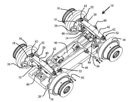
[0027] Referring to figure 1, the unsuspended part of a bogie 10
10 includes two wheel axles 12, 14 carrying the usual left and
right track wheels 16. Each wheel axle 12, 14 is journalled in a
pair of left and right axle boxes 18 located between the track
wheels 16. Each axle box 18 is provided with front and rear pans
on which the lower end of a rubber spring 22 of the primary
15 suspension seats.
[0028] Each primary suspension spring 22 is screwed at its upper
end to a spindle 24 that projects through a side bogie frame
member 26 and is secured thereto, as illustrated in figure 2.
20 The bogie frame 27 is provided with a pair of tubular transoms
28 and front and rear cross-members 30 welded to the side
members 26. The vehicle body is supported on the bogie side
members by an air spring assembly.
[0029] As shown in figure 2, the bogie is provided with a pair
of cross-members 40, 42 for supporting the linear induction
motor 44. Each cross-member 42, 44 extends above one of the
wheel axles 12, 14 and is provided with two mounting eyes 46 at
its ends. As illustrated in figure 3, each mounting eye 46 has a
through hole and is sandwiched between an upper and a lower
rubber spring 48, 50 of a resilient connection 52 to allow
CA 02571912 2013-11-04
'
16
connection to the axle boxes 18. The rubber springs consist of a
rubber body bonded to an upper and a lower rigid plate and are
maintained on an adjuster sleeve 56 by a locking ring 58. The
adjuster sleeve 56 is provided with an internal thread screwed
on the external thread of an adjuster tube 60. The adjuster tube
60 cooperates at its axial inner ends with a mounting stud 62 in
screwed on the axle box housing 64, so as to freely rotate about
the stud axis without radial play. A hexagonal locknut 66 is
screwed on the upper end of the stud 62 to prevent axial
movement of the adjuster tube 60. A hexagonal locking nut 68 can
be screwed on the adjuster tube 60 to lock the position of the
adjuster sleeve 56.
(00301 The rubber springs 48, 50 provide a stiff vertical
suspension of each cross-members 40, 42 relative to the axle
boxes 18, but have low rotational stiffness and allow the cross-
members to rotate relative to a horizontal transversal axis 76
parallel to the axle 12, 14 and crossing the left and right
studs 62 at a centre of rotation of the resilient connection 52.
[0031) A system of five vertical links 80, 82, 84, 86, 88
support the inductor 44 relative to the cross-members. This
system includes a pair of links 80, 82 centrally located at
equal distance from the left and right mounting studs 62 on
opposite sides of one of the cross-members 40. The system of
vertical links also includes three vertical links 84, 86, 88 for
connecting the inductor 44 to the other cross-member 42. The
link 84 is located longitudinally on one side of the cross-
member, at equal distance from the mounting studs 62, while the
other two links 86, 88 are located longitudinally on the other
side of the cross-member and are laterally spaced apart from one
CA 02571912 2013-11-04
17
another at equal distance from the link 84. The five links are
pivotally connected to the cross-members 40, 42 and to the
inductor 44 through metal ball bearings. Thanks to these
universal connections, the forces transmitted by the links to
the cross-members are balanced and the point of application of
the resultant force applied by the links on each cross-member is
located on the rotation axis of the cross-member at equal
distance from the mounting studs. This system of five links is
therefore equivalent to a three-point levelling scheme.
(0032] A longitudinal connecting rod 90 transmits the thrust
forces directly from the inductor 44 to one of the transom tubes
28 of the bogie frame 27. Two lateral links 92, preferably
located on the same side of the bogie, transmit lateral forces
from the inductor 44 to one of the side members 26 of the bogie
frame.
[0033] Each pair of adjuster sleeve 56 and adjuster tube 60
constitutes a height adjuster integrated in the resilient
connection 52, which can be accessed from above through an
aperture in the floor of the car body and is operated as
follows. The locking nut 68 is released and slacken by one or
two turns. The locknut 66 is then released to allow free
rotation of the threaded tube. A wrench can then be engaged on
the hexagonal head of the threaded tube to turn it so as to
raise or lower the adjuster sleeve as required. Once the desired
position has been reached, the locknut is tightened and the
locking nut is tightened.
[0034] The four height adjusters are used to adjust the position
of the cross-members in relation to the axle boxes and to the
reaction rail on the ground. The height adjustment procedure is
CA 02571912 2013-11-04
18
as follows: The bogie is first put on a section of track, which
is both straight and level. The distance between the linear
induction motor and the reaction rail is precisely measured at
say four locations. Preferably, these locations are towards the
outside edges of the inductor and in line with the cross-
members. The measurement locations are symmetrical about the
track centre line.
[0035] The cross level error is determined for each longitudinal
end of the inductor as the difference in height between the two
measurement locations at the corresponding end of the inductor.
An average cross level error is then determined as the average
of the front and rear cross level errors.
[0036] Adjustment of the cross level error can be made by adding
half of the average cross level error to the low side of the
inductor and subtracting half of the value from the high side,
on cross-member 42. No adjustment needs to be made on the cross-
member 40, since the corresponding end of the inductor is
centrally mounted on the cross-member.
[0037] Similarly, the average height is determined at each
longitudinal end of the inductor and the deviation from a
predetermined nominal height is calculated. This error is the
adjustment that needs to be made on the height adjusters of the
corresponding cross-member.
[0038] Obviously, the cross level errors and the height error
can be computed at the same time and the adjustments can be made
in one step.
CA 02571912 2013-11-04
19
[0039] The height measurement could be made at three locations
instead of four, one central location close to cross-member 40
and two locations towards the ends of cross-member 42.
[0040] The railway bogie described hereinbefore can be used with
any kind of railway vehicle, alone or in pairs to carry a car
body of any desired construction.
[0041] As can readily be appreciated, the suspension arrangement
described above can be used to support a reaction plate of a
linear induction motor, with the linear inductor being mounted
in the guide rail for the vehicle.
[0042] The universal connections of the links can be provided
with stiff resilient means.