Language selection

Search

Patent 2572365 Summary

Third-party information liability

Some of the information on this Web page has been provided by external sources. The Government of Canada is not responsible for the accuracy, reliability or currency of the information supplied by external sources. Users wishing to rely upon this information should consult directly with the source of the information. Content provided by external sources is not subject to official languages, privacy and accessibility requirements.

Claims and Abstract availability

Any discrepancies in the text and image of the Claims and Abstract are due to differing posting times. Text of the Claims and Abstract are posted:

  • At the time the application is open to public inspection;
  • At the time of issue of the patent (grant).
(12) Patent: (11) CA 2572365
(54) English Title: METHOD FOR STARTING HIGH-PERFORMANCE ENTRAINED FLOW GASIFICATION REACTORS
(54) French Title: METHODE PERMETTANT DE DEMARRER DES REACTEURS DE GAZEIFICATION A LIT ENTRAINE A HAUTE PERFORMANCE
Status: Granted
Bibliographic Data
(51) International Patent Classification (IPC):
  • F23Q 9/10 (2006.01)
(72) Inventors :
  • FISCHER, NORBERT (Germany)
  • SCHINGNITZ, MANFRED (Germany)
(73) Owners :
  • SIEMENS AKTIENGESELLSCHAFT (Germany)
(71) Applicants :
  • SIEMENS AKTIENGESELLSCHAFT (Germany)
(74) Agent: BORDEN LADNER GERVAIS LLP
(74) Associate agent:
(45) Issued: 2014-09-16
(22) Filed Date: 2006-12-28
(41) Open to Public Inspection: 2007-12-28
Examination requested: 2011-11-17
Availability of licence: N/A
(25) Language of filing: English

Patent Cooperation Treaty (PCT): No

(30) Application Priority Data:
Application No. Country/Territory Date
10 2006 030 079.3 Germany 2006-06-28

Abstracts

English Abstract

The invention relates to a method for starting high-performance entrained flow gasification reactors with a combination burner and an ignition and pilot burner or a plurality of pulverized fuel burners that are disposed around the ignition and pilot burners for autothermal partial oxidation of pulverized solid fuels such as lignite and hard coal, petroleum coke or solid grindable carbon-containing residues that are pneumatically supplied to the combination burner with an oxygen-containing gasifying agent at operating pressures of up to 100 bar by means of an ignition flame, characterized in that the ignition and pilot burner is ignitedsubstoichiometrically with a fuel gas and the oxygen-containing gasification means and that the entrained flow gasification reactor is thus brought to the pressure intended and that an intended flow of a fuel gas is supplied thereafter with a partial flow of the oxygen--containing gasification agent at a substoichiometric ratio through the pulverized fuel lines leading to the pulverized fuel burner and ignited by the flame of the ignition and pilot burner and that next, the pulverized fuel intended for partial oxidation is supplied together with further oxygen-containing gasifying agent through the supply lines to the pulverized fuel burner and is ignited by the flame of the ignition burner and by the fuel gas flames at the pulverized fuel burner. The advantage of the invention is that the ignition heat needed can be significantly reduced, utilizing a combination burner or a multiple burner array.


French Abstract

L'invention concerne une méthode permettant de démarrer des réacteurs de gazéification à lit entraîné à haute performance grâce à un brûleur polycombustible et à un brûleur d'allumage et de veilleuse ou grâce à plusieurs brûleurs à charbon pulvérisé disposés autour des brûleurs d'allumage et de veilleuse. L'objectif est l'oxydation partielle autothermique des combustibles solides pulvérisés, comme le lignite et le charbon dur, le coke de pétrole ou des résidus solides triturables contenant du carbone acheminés de façon pneumatique vers le brûleur polycombustible avec un agent gazéifiant contenant de l'oxygène, à des pressions de fonctionnement allant jusqu'à 100 bar, à l'aide d'une flamme d'allumage. La méthode se caractérise ainsi : par le fait que le brûleur d'allumage et de veilleuse est allumé de façon sous-stchiométrique avec un gaz combustible et un moyen de gazéification contenant de l'oxygène; que le réacteur de gazéification à lit entraîné est ainsi porté à la pression voulue; que l'écoulement voulu d'un gaz combustible est acheminé par la suite à l'aide d'un écoulement partiel de l'agent de gazéification contenant de l'oxygène selon un rapport sous-stchiométrique par le biais des conduites de combustible pulvérisé menant au brûleur de combustible pulvérisé et allumé par la flamme du brûleur d'allumage et de veilleuse; et que, ensuite, le combustible pulvérisé prévu pour l'oxydation partielle est acheminé en même temps que davantage d'agent de gazéification contenant de l'oxygène, par les conduites d'acheminement, vers le brûleur de combustible pulvérisé et est allumé par la flamme du brûleur d'allumage ainsi que par les flammes du gaz combustible du brûleur de combustible pulvérisé. L'invention a pour avantage que la chaleur d'allumage nécessaire peut être réduite de façon significative grâce au recours à un brûleur polycombustible ou à une gamme de multiples brûleurs.

Claims

Note: Claims are shown in the official language in which they were submitted.


7
CLAIMS:
1. A method for starting a high-performance entrained flow gasification
reactor with a
combination burner containing an ignition and pilot burner and at least one
pulverized fuel
burner at a top of the reactor, for autothermal partial oxidation of
pulverized solid fuels such
as lignite and hard coal, petroleum coke or solid grindable carbon-containing
residues,
wherein for each fuel burner there are a plurality of fuel supply lines
arranged for supplying
an amount of pulverized fuel to the pulverized fuel burner with an oxygen-
containing
gasifying agent at operating pressures of up to 100 bar and temperatures
ranging between
1,200° C. and 1,800° C. by means of an ignition flame, the
method comprising the following
steps in order:
igniting the ignition and pilot burner substoichiometrically with a fuel gas
and the
oxygen-containing gasifying agent;
bringing the entrained flow gasification reactor to a selected pressure of up
to 100
bar;
supplying through at least one of the plurality of fuel supply lines a flow of
the fuel gas
to the pulverized fuel burner;
supplying an oxygen-containing gasification agent for the fuel gas at a
substoichiometric ratio through a separate line to the pulverized fuel burner;
igniting the fuel gas with a flame of the ignition and pilot burner;
supplying the pulverized fuel together with further oxygen-containing
gasifying agents
through the fuel supply lines to the pulverized fuel burner,
wherein the fuel supply lines are activated in successive steps only one
supply line at
a time in such a manner that after one of the fuel supply lines has been
activated, an
appropriate flow of gasification agent corresponding to a selected
substoichiometric .lambda. ratio is
added first, with a next fuel supply line being activated only after igniting
the pulverized fuel
of a previously activated fuel supply line by the flame of the ignition and
pilot burner and by
fuel gas flames at the pulverized fuel burners.
2. The method according to claim 1, wherein the pulverized fuel is supplied
as a
pulverized fuel-water or pulverized fuel-oil suspension.


8
3. The method according to claim 1, wherein an amount of heat needed for
ignition of
the pulverized fuel is approximately .05 to 0.5 times a product of the
pulverized fuel mass
flow of one supply line only and its heating value.
4. The method according to claim 1, wherein an amount of heat needed for
ignition of
the pulverized fuel is greater than 0.05 times a product of the pulverized
fuel mass flow of
one supply line only and its heating value.
5. The method as set forth in claim 1, wherein the amount of fuel gas and
of oxygen in
the reactor is monitored by a higher order, independent, automatically acting
safety system.
6. A method for starting a high-performance entrained flow gasification
reactor with an
ignition and pilot burner and a plurality of burners separately disposed
around the ignition
and pilot burner, all of said burners being arranged at a top of the reactor,
for autothermal
partial oxidation of pulverized solid fuels such as lignite and hard coal,
petroleum coke or
solid grindable carbon-containing residues, wherein for each fuel burner there
are a plurality
of fuel supply lines arranged for supplying an amount of pulverized fuel to
the pulverized fuel
burners with an oxygen-containing gasifying agent at operating pressures of up
to 100 bar
and temperatures ranging between 1,200° C. and 1,800° C. by
means of an ignition flame,
the method comprising the following steps in order:
igniting the ignition and pilot burner substoichiometrically with a fuel gas
and the
oxygen-containing gasifying agent;
bringing the entrained flow gasification reactor containing free oxygen to a
selected
pressure of up to 100 bar;
supplying through at least one of the plurality of fuel supply lines a flow of
the fuel gas
to each pulverized fuel burner;
supplying an oxygen-containing gasification agent for the fuel gas at a
substoichiometric ratio through a separate line to the pulverized fuel burner;
igniting the fuel gas with a flame of the ignition and pilot burner;
supplying the pulverized fuel together with further oxygen-containing
gasifying agents
through the fuel supply lines to each pulverized fuel burner,
wherein the fuel supply lines are activated in successive steps only one
supply line at
a time to each pulverized fuel burner in such a manner that after one of the
fuel supply lines


9
has been activated, an appropriate flow of gasification agent corresponding to
a selected
substoichiometric A ratio is added first, with a next fuel supply line being
activated only after
igniting the pulverized fuel of a previously activated fuel supply line by the
flame of the
ignition and pilot burner and by fuel gas flames at the pulverized fuel
burners.
7. A method for starting a high-performance entrained flow gasification
reactor with a
combination burner containing an ignition and pilot burner and at least one
slurry burner
arranged at a top of the reactor, for autothermal partial oxidation of
slurries, wherein there
are a plurality of fuel supply lines arranged for supplying an amount of
slurry fuel to the slurry
burner with an oxygen-containing gasifying agent at operating pressures of up
to 100 bar and
temperatures ranging between 1,200° C. and 1,800° C. by means of
an ignition flame, the
method comprising the following steps in order:
igniting the ignition and pilot burner substoichiometrically with a fuel gas
and the
oxygen-containing gasifying agent;
bringing the entrained flow gasification reactor containing free oxygen to a
selected
pressure of up to 100 bar;
supplying through at least one of the plurality of fuel supply lines a flow of
the fuel gas
to the slurry burner;
supplying an oxygen-containing gasification agent for the fuel gas at a
substoichiometric ratio through a separate line to the pulverized fuel burner;
igniting the fuel gas with a flame of the ignition and pilot burner;
supplying the slurry fuel together with further oxygen-containing gasifying
agents
through the fuel supply lines to the slurry burner,
wherein the fuel supply lines are activated in successive steps only one
supply line at
a time to the slurry burner in such a manner that after one of the fuel supply
lines has been
activated, an appropriate flow of gasification agent corresponding to a
selected
substoichiometric A ratio is added first, with a next fuel supply line being
activated only after
igniting the slurry fuel in a previously activated fuel supply line by the
flame of the ignition and
pilot burner and by fuel gas flames at the slurry burner.
8. A method for starting a high-performance entrained flow gasification
reactor with a
combination burner containing an ignition and pilot burner and a plurality of
slurry burners
separately disposed around the ignition and pilot burner, all of said burners
being arranged at


10
a top of the reactor, for autothermal partial oxidation of slurries, wherein
there are a plurality
of fuel supply lines arranged for supplying an amount of slurry fuel to each
slurry burner with
an oxygen-containing gasifying agent at operating pressures of up to 100 bar
and
temperatures ranging between 1,200° C. and 1,800° C. by means of
an ignition flame, the
method comprising the following steps in order:
igniting the ignition and pilot burner substoichiometrically with a fuel gas
and the
oxygen-containing gasifying agent;
bringing the entrained flow gasification reactor containing free oxygen to a
selected
pressure of up to 100 bar;
supplying through at least one of the plurality of fuel supply lines a flow of
the fuel gas
to each of the slurry burners;
supplying an oxygen-containing gasification agent for the fuel gas at a
substoichiometric ratio through a separate line to the pulverized fuel burner;
igniting the fuel gas with a flame of the ignition and pilot burner;
supplying the slurry fuel together with further oxygen-containing gasifying
agents
through the fuel supply lines to each of the slurry burners,
wherein the fuel supply lines are activated in successive steps only one
supply line at
a time to each slurry burner in such a manner that after one of the fuel
supply lines has been
activated, an appropriate flow of gasification agent corresponding to a
selected
substoichiometric A ratio is added first, with a next fuel supply line being
activated only after
igniting the slurry fuel in a previously activated fuel supply line by the
flame of the ignition and
pilot burner and by fuel gas flames at the slurry burners.

Description

Note: Descriptions are shown in the official language in which they were submitted.


CA 02572365 2006-12-28

1
Method for Starting High-Performance Entrained Flow Gasification Reactors
Field of the Invention
The invention relates to a method for starting high-performance entrained flow
gasification
reactors. The method finds application in high-performance entrained flow
gasifiers as they
may be utilized for synthesis gas supply of large synthesis facilities. While
ensuring technical
safety and short startup time, the invention allows starting the autothermal
partial oxidation of
pulverized fuels such as lignite and hard coal, petroleum coke, solid
grindable carbon-
containing residues but also solid-liquid suspensions, called slurries, with
an oxygen-
containing gasification agent at operating pressures of up to 100 bar.

Background of the Invention
The configuration of the device for pulverized fuel supply inclusive of the
supply lines and
their association with the pulverized fuel burners as well as the arrangement
of the burners
on the reactor head for entrained flow gasifiers is described in DE 10 2005
048 488.3. This
document discloses a method for gasifying pulverized fuels in which solid
fuels are converted
in the entrained flow with an oxidation agent containing free oxygen through
partial oxidation
at pressures ranging between ambient pressure and 80 bar and at temperatures
ranging
between 1,200 and 1,900 C at high reactor performances ranging between 500 MW
and
1,500 MW. The method consists of the partial technologies: dosing the fuel,
gasification
reaction in a gasification reactor with cooled reaction chamber contour,
quench cooling, raw
gas scrubbing, partial condensation. A fuel, preferably a pulverized fuel,
having a moisture
content of < 10 wt.-% and a grain size of < 200 pm, is given into a plurality
of synchronized
dosing systems that supply the fuel, preferably the pulverized fuel, through
supply pipes to a
plurality of gasification burners disposed on the head of a reactor, said
burners being
disposed symmetrically and containing additional oxygen feed lines.

Further, the method finds application in plants, in which pulverized fuel
flows, preferably
three pulverized fuel flows, flow from a bin to pressurized lock hoppers that
lead the
pulverized fuel flows to feeder vessels from which one or a plurality of
preferably three supply
lines lead to a plurality of preferably three pulverized fuel burners in a
gasification reactor.
The high-performance reactor has a piurality of gasification burners
symmetrically disposed
at the head thereof and an ignition and pilot burner.

DD 278692 describes a method for starting reactors with a water-cooled tube
wall
construction. It explains that the gasification materials are ignited at full
operating pressure,
the thermal output Q delivered by the ignition and pilot burner having to be
greater than or


CA 02572365 2006-12-28

2
equal to the required ignition heat QZ needed by the starting amount of
gasification material
corresponding to the miminum permanent output of the pulverized fuel burner(s)
if one wants
to achieve reliable and instantaneous ignition directly before and during the
startup of the
pulverized fuel burner(s). The disadvantage thereof is that the thermal
performance of the
ignition and pilot burner must be very high with high-performance gasification
reactors of up
to 1,500 MW.

It is desirable to start high-performance entrained flow gasification reactors
of > 200 MW for
the autothermal partial oxidation of pulverized fuels such as lignite and hard
coal, petroleum
coke, solid grindable carbon-containing residues but also solid-liquid
suspensions, called
slurries, at operating pressures of up to 100 bar at reduced thermal
performance of the
ignition and pilot burner.

Summary of the Invention
In one aspect, the present invention provides a method for starting high-
performance
entrained flow gasification reactors with a combination burner containing an
ignition and pilot
burner as well as a pulverized fuel burner or a multiple burner array, with a
plurality of
pulverized fuel burners being disposed separately around an ignition and pilot
burner for
autothermal partial oxidation of pulverized solid fuels that are pneumatically
supplied to the
combination burner with an oxygen-containing gasifying agent at operating
pressures of up
to 100 bar and temperatures ranging between 1,200 C and 1,800 C by means of
an ignition
flame, comprising the steps of igniting the ignition and pilot burner
substoichiometrically with
a fuel gas and the oxygen-containing gasification means, thus bringing the
entrained flow
gasification reactor to the desired pressure; thereafter supplying a desired
flow of fuel gas
with a partial flow of the oxygen-containing gasification agent at a
substoichiometric ratio
through the pulverized fuel lines leading to the pulverized fuel burner which
fuel gas is ignited
by the flame of the ignition and pilot burner; and thereafter supplying the
pulverized fuel for
partial oxidation, together with further oxygen-containing gasifying agent,
through the supply
lines to the pulverized fuel burner, thus igniting the pulverized fuel by the
flame of the ignition
burner and by the fuel gas flames at the pulverized fuel burner.

In principle, the method of the invention is applicable to various burner
arrays in reactors.

The ignition and pilot burner is disposed in the center, i.e., in the center
of the vertical axis of
the gasification reactor. The ignition and pilot burner can be disposed in the
center of a
burner, for example a pulverized fuel burner, so that a combination burner is
provided. The
ignition and pilot burner may however also be disposed in the center between
pulverized fuel


CA 02572365 2006-12-28

3
burners. The pulverized fuel burners may for example be staggered about the
central ignition
and pilot burner.

The centrally disposed ignition and pilot burner is ignited with a high-
voltage ignition device.
Immediately thereafter, the output of the ignition and pilot burner and the
pressure of the
entrained flow gasification reactor, inclusive of the downstream raw gas
system is increased
to the maximum ignition and pilot burner performance and to the operating
pressure of the
plant.

Once the operating pressure has been achieved, fuel gas is supplied through
one or a
plurality of pulverized fuel supply lines and burned together with an oxygen-
containing
gasification agent suppliedat substoichiometric ratio through separate lines.

Once the operating pressure has been achieved, the fuel gas flowing into the
gasification
reactor through pulverized fuel supply lines is added and ignited. If three
separate pulverized
fuel burners are provided, they are supplied with fuel gas through pulverized
fuel supply lines
and with an oxygen-containing gasification agent suppliedat substoichiometric
ratio through
separate lines. When the mixture of fuel gas and pulverized fuel is ignited,
the starting
conditions for supplying the pulverized fuels such as lignite and hard coal,
petroleum coke,
solid grindable carbon-containing residues but also solid-liquid suspensions
to the entrained
flow reactor are fulfilled. The supply of gasification material is started by
successive
connection of only one supply line at a time in such a manner that after the
supply line has
been connected, an apportioned flow of gasification agent corresponding to the
selected A
ratio is added first, with the next fuel line being connected thereafter only.
With a multiple
burner array, one or a plurality of fuel lines may be activated one after the
other for each
burner. Not yet connected fuel lines will then be connected in an analogous
fashion.

With this way of proceeding, if the igniting flame is to reliably and
instantaneously ignite the
fuel immediately before and during startup of the burner(s), the igniting heat
provided should
merely correspond to the minimum permanent output of a fuel supply pipe. Using
the method
and utilizing a combination burner, the need for ignition heat can be reduced
by 60 %,
utilizing a multiple burner array, by up to 90 %.

Brief Description of the Drawings
The following exemplary embodiments and figures are intended to provide a
better
understanding of the invention. In the Figures:


CA 02572365 2006-12-28

4
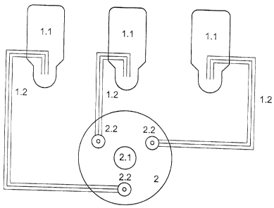
Fig. 1 shows a pulverized fuel feeder vessel with pulverized fuel supply lines
for supplying
pulverized fuel to the gasification reactor having a combination burner, and

Fig. 2 shows a pulverized fuel feeder vessel with pulverized fuel supply lines
for supplying
pulverized fuel to the gasification reactor having a multiple burner array.

Detailed Description of the Invention
The first example intended to provide a better understanding of the invention
is a gasification
reactor with a combination burner as shown in Fig. 1.
The combination burner, which is attached to the head of the reactor 2,
consists of the
ignition and pilot burner with ignition device 2.3 and the pulverized fuel
burner part 2.4. For
supplying the pulverized fuel burner with pulverized fuel, the amount of
pulverized fuel
needed is supplied through three supply lines 1.2 from a feeder vessel 1.1.
With a gasification reactor 2 with a gross output of 500 MW and the
combination burner 2.4
described, this corresponds to an amount of pulverized coal of 78 Mg/h. The
pulverized fuel
has a heating value of 23 MJ/kg. Pulverized fuel is supplied from the feeder
vessel 1.1 to the
combination burner 2.4 by means of the three supply lines 1.2 mentioned, that
is to say 26
Mg/h per line. The maximum initial output of a fuel line 1.2 is 11.7 Mg/h.
This initial output
results in a minimum ignition heat of 13.5 GJ/h. In prior art, a minimum
ignition heat of 40.5
GJ/h would be necessary at startup.

After the operating pressure in the reactor 2 and the ignition output of the
ignition and pilot
burner 2.3 is achieved, the pulverized fuel burner 2.4 is started in such a
manner that the
automatic control unit causes fuel gas and oxygen-containing gasification
agent to be
supplied to the pulverized fuel burner 2.4 so that the igniting flame of the
ignition and pilot
burner 2.3 first causes a fuel gas-oxygen flame to ignite at each of the three
pulverized fuel
supply lines 1.2. The amount of fuel gas and of oxygen is monitored by a
higher order safety
system. The sensible heat quantity released by the ignition burner flame and
the three fuel
gas-oxygen flames at the pulverized fuel burner 2.4 is so high that it is made
certain that the
11.7 Mg/h pulverized coal flowing into the reactor 2 will ignite by means of
the automatic
control unit causing the first supply line 1.2 to open and the oxygen-
containing gasification
agent to increase. After that, the second and third pulverized coal supply
lines 1.2 are
started. The amount of fuel gas, of pulverized coal and of oxygen is monitored
by the higher
order safety system. Once the pulverized coal burner 2.4 has been started, the
supply of fuel
gas to the pulverized coal burner 2.4 is stopped.


CA 02572365 2006-12-28

Another example is described with the same burner. The ignition and pilot
burner 2.3 is
ignited in the same manner as in example 1. Once the ignition and pilot burner
has reached
its full output and the desired pressure in the gasification reactor 2 has
been achieved, the
amount of fuel gas corresponding to the necessary minimum ignition heat of
13.5 MJ/h is
5 added through a pulverized fuel supply pipe 1.2 and ignited with an oxygen-
containing
gasification agent. Once the flame is stable, the other two pulverized fuel
lines 1.2 are
immediately brought to react with the solid fuel or slurry and the oxygen-
containing oxidation
agent. Next, these three pulverized fuel lines 1.2 are adjusted upward to the
nominal output
of 26 Mg/h per line.
In a third example, the method will be described with gasification reactors
having a multiple
burner array as shown in Fig. 2. A pulverized coal amount of 240 Mg/h is
supplied to a
gasification reactor 2 with a gross output of 1.500 MW as shown in Fig. 2. The
pulverized fuel
has a heating value of 24.7 MJ/kg. At the head of the gasification reactor 2
in which the
pulverized hard coal is gasified with a gasification agent containing free
oxygen, there are
mounted an ignition and pilot burner 2.1 and three pulverized coal burners 2.2
that are
staggered 120 apart about the ignition and pilot burner. The pulverized coal
burners 2.2 are
each loaded from one feeder vessel 1.1, each unit supplying 1/3 of the total
amount of
pulverized fuel, that is 80 Mg/h into the reactor 2 by means of three
respective supply lines
1.2, that is 26.7 Mg/h per line. The initial output of a supply line 1.2 is 12
Mg/h. Based on this
initial output of a line 1.2, a minimum ignition heat of 14.8 GJ/h only is
needed as compared
to the 133.4 GJ/h needed with the prior art method. Once the operating
pressure in the
reactor 2 and the ignition output of the ignition and pilot burner 2.1 are
achieved, the three
pulverized coal burners 2.2 are started in such a manner that fuel gas and
oxygen-containing
gasification agent are supplied to the pulverized coal burners 2.2 through the
automatic
control unit so that the ignition flame of the ignition and pilot burner 2.1
causes at first a fuel
gas-oxygen flame to ignite at each of the three pulverized coal burners 2.2.
The amount of
fuel gas and of oxygen is monitored by a higher order safety system. The
sensible heat
quantity released by the flame of the ignition and pilot burner 2.1 and the
three fuel gas-
oxygen flames at the pulverized fuel burners 2.2 is so high that it is made
certain that the 12
Mg/h pulverized coal flowing into the reactor 2 will ignite by means of the
automatic control
unit causing the first supply line 1.2 to open and the oxygen-containing
gasification agent to
increase. Thereafter, a pulverized coal supply line 1.2 of the second
pulverized coal burner
2.2 is started with increased gasification agent and then, of the third
pulverized coal burner
2.2. Startup is continued in the sequence described until all of the
pulverized coal supply
lines 1.2 are in operation. The amount of fuel gas, pulverized coal and oxygen
is monitored


CA 02572365 2006-12-28

6
by the higher order safety system. Once the pulverized coal burners 2.2 are in
operation, the
supply of fuel gas to the pulverized coal burners 2.2 is stopped.

In a fourth exemplary embodiment, the gasification reactor 2 is started with
the aid of the
ignition and pilot burner 2.1 in a manner analogous to example 3. Once the
desired operation
pressure and full ignition and pilot burner output are achieved, the amount of
fuel gas
corresponding to a thermal output of 14.8 GJ/h is supplied through one of the
three
pulverized coal burners 2.2 and burned substoichiometrically. Next, the other
two pulverized
coal burners 2.2 are started with pulverized coal, one supply pipe 1.2 being
first supplied with
the minimum amount of pulverized fuel of 12 Mg/h and then the other two supply
pipes 1.2,
also with 12 Mg/h each. After the burners 2.2 have reached the minimum
starting amount of
3 x 12 = 36 Mg/h each, they are adjusted upward to the operating performance
of 80 Mg/h
for each burner 2.2. In a comparable manner, the burner 2.2, which is at first
supplied with
fuel gas, is brought to a performance of 80 Mg/h by stopping the fuel gas
supply.
In a fifth exemplary embodiment, the method for gasification reactors 2 for
slurry gasification
having a combination burner and a multiple burner array will be illustrated.
In place of the dry
pneumatic pulverized fuel supply described in the examples 1-4, the pulverized
fuel for
certain fuels such as hard coal, petroleum coke and solid grindable carbon-
containing
residues can be introduced into the gasification reactor in the form of a
pulverized fuel-water
or pulverized fuel-oil suspension, called slurry. For a reactor 2 with an
output of 500 MW and,
as a result thereof, a pulverized fuel need of 78 Mg/h, the amount to be
supplied at a solids
concentration of 60 wt.-% in the slurry comes up to 130 Mg/h. The minimum
ignition heat is
13.56 MJ/h like in Example 1, which corresponds to a slurry amount of 20 Mg/h.
The startup
process itself takes place like in the afore mentioned examples.

List of the Numerals used
1.1 pulverized fuel feeder vessel
1.2 pulverized fuel supply lines
2 gasification reactor
2.1 ignition and pilot burner
2.2 pulverized fuel burner
2.3 ignition and pilot burner of the combination burner
2.4 pulverized fuel burner of the combination burner

Representative Drawing
A single figure which represents the drawing illustrating the invention.
Administrative Status

For a clearer understanding of the status of the application/patent presented on this page, the site Disclaimer , as well as the definitions for Patent , Administrative Status , Maintenance Fee  and Payment History  should be consulted.

Administrative Status

Title Date
Forecasted Issue Date 2014-09-16
(22) Filed 2006-12-28
(41) Open to Public Inspection 2007-12-28
Examination Requested 2011-11-17
(45) Issued 2014-09-16

Abandonment History

There is no abandonment history.

Maintenance Fee

Last Payment of $458.08 was received on 2022-12-19


 Upcoming maintenance fee amounts

Description Date Amount
Next Payment if small entity fee 2023-12-28 $253.00
Next Payment if standard fee 2023-12-28 $624.00

Note : If the full payment has not been received on or before the date indicated, a further fee may be required which may be one of the following

  • the reinstatement fee;
  • the late payment fee; or
  • additional fee to reverse deemed expiry.

Patent fees are adjusted on the 1st of January every year. The amounts above are the current amounts if received by December 31 of the current year.
Please refer to the CIPO Patent Fees web page to see all current fee amounts.

Payment History

Fee Type Anniversary Year Due Date Amount Paid Paid Date
Application Fee $400.00 2006-12-28
Maintenance Fee - Application - New Act 2 2008-12-29 $100.00 2008-11-12
Registration of a document - section 124 $100.00 2009-04-21
Maintenance Fee - Application - New Act 3 2009-12-29 $100.00 2009-11-05
Maintenance Fee - Application - New Act 4 2010-12-29 $100.00 2010-11-02
Maintenance Fee - Application - New Act 5 2011-12-28 $200.00 2011-11-02
Request for Examination $800.00 2011-11-17
Maintenance Fee - Application - New Act 6 2012-12-28 $200.00 2012-11-26
Maintenance Fee - Application - New Act 7 2013-12-30 $200.00 2013-11-04
Final Fee $300.00 2014-06-27
Maintenance Fee - Patent - New Act 8 2014-12-29 $200.00 2014-11-12
Maintenance Fee - Patent - New Act 9 2015-12-29 $200.00 2015-11-04
Maintenance Fee - Patent - New Act 10 2016-12-28 $250.00 2016-11-09
Maintenance Fee - Patent - New Act 11 2017-12-28 $250.00 2017-11-17
Maintenance Fee - Patent - New Act 12 2018-12-28 $250.00 2018-11-15
Maintenance Fee - Patent - New Act 13 2019-12-30 $250.00 2019-11-05
Maintenance Fee - Patent - New Act 14 2020-12-29 $250.00 2020-11-30
Maintenance Fee - Patent - New Act 15 2021-12-29 $459.00 2021-12-20
Maintenance Fee - Patent - New Act 16 2022-12-28 $458.08 2022-12-19
Owners on Record

Note: Records showing the ownership history in alphabetical order.

Current Owners on Record
SIEMENS AKTIENGESELLSCHAFT
Past Owners on Record
FISCHER, NORBERT
SCHINGNITZ, MANFRED
Past Owners that do not appear in the "Owners on Record" listing will appear in other documentation within the application.
Documents

To view selected files, please enter reCAPTCHA code :


To view images, click a link in the Document Description column. To download the documents, select one or more checkboxes in the first column and then click the "Download Selected in PDF format (Zip Archive)" or the "Download Selected as Single PDF" button.

List of published and non-published patent-specific documents on the CPD .

If you have any difficulty accessing content, you can call the Client Service Centre at 1-866-997-1936 or send them an e-mail at CIPO Client Service Centre.


Document
Description 
Date
(yyyy-mm-dd) 
Number of pages   Size of Image (KB) 
Representative Drawing 2007-12-03 1 4
Abstract 2006-12-28 1 35
Description 2006-12-28 6 347
Claims 2006-12-28 2 54
Drawings 2006-12-28 2 20
Cover Page 2007-12-14 1 49
Claims 2013-11-01 4 180
Representative Drawing 2013-12-30 1 7
Cover Page 2014-08-20 1 51
Correspondence 2007-02-02 1 28
Assignment 2006-12-28 3 85
Correspondence 2008-01-15 2 36
Correspondence 2008-03-12 4 124
Assignment 2009-04-21 3 134
Correspondence 2009-09-25 1 18
Prosecution-Amendment 2011-11-17 1 29
Prosecution-Amendment 2013-05-02 2 89
Prosecution-Amendment 2013-11-01 6 249
Correspondence 2014-06-27 1 32