Note: Descriptions are shown in the official language in which they were submitted.
CA 02572394 2006-12-27
WO 2006/023451 PCT/US2005/029002
1
DRYING GLOVE
CLAIM OF BENEFIT
This application claims benefit of United States Provisional Patent
Application
60/601,710, filed on 16 August 2004, which is herein incorporated by
reference.
FIELD OF THE INVENTION
The present invention relates to gloves that are used for specific utility. In
particular, the present invention relates to gloves for the human hands, and
more
specifically to gloves for the human hands that are worn while handling an
object for
the purpose of drying or polishing it.
BACKGROUND OF THE INVENTION
People who need to dry a moist or wet object in the kitchen, home, garage, or
elsewhere, or otherwise need to remove liquid from an object, generally use a
piece of
cloth made of cotton, paper towel, or other moisture absorbent material. The
method
of operation is usually dabbing or wiping the wet surface with the piece of
cloth in
order to absorb and remove moisture. During this operation, the wet object is
handled
either by bare hand or with the same piece of cloth used for drying, while it
is being
dried.
While this method may be partially effective for drying, holding the object
with bare hand has the disadvantage of depositing fingerprints and smear marks
on
the object. Attempting to hold the object with the same cloth used for drying
it, is
difficult in that the same piece of fabric is employed in performing two
entirely
different tasks of holding securely and drying. Trying to hold the object with
a
CA 02572394 2006-12-27
WO 2006/023451 PCT/US2005/029002
2
second piece of cloth is awkward in that it is difficult to juggle the object
and the two
pieces of cloth. Therefore, there is a risk of dropping the object.
Furthermore, using a
piece of cloth poses an additional challenge in drying. Thorough drying of
every
crevice and contour of an object including surface recessions, grooves,
channels, cuts,
openings, internal parts, and other hard to reach areas is difficult with a
regular towel
or paper towel. As a result, one of the following undesirable effects may
occur. The
object is only partially dried, smear marks and fingerprints are deposited and
left on
the object, or the object is dropped and damaged.
Similarly, when people want to polish an object, for example silverware, they
use a simple rag. While using a rag may be somewhat effective, it is usually
unsafe,
because the rag offers minimal protection from the polishing agent used. These
polishing agents usually contain chemicals that are harmful to the skin of the
user.
All of the shortcomings of a piece of cloth for drying mentioned above also
apply to
using a rag for polishing. In addition, a polishing agent may cause great harm
to the
user's hand. Further, depositing fingerprints and smear marks on an object
being
polished, counteracts the purpose of the polishing job. Holding the object
securely
while working on its surfaces with a simple rag is not easy and presents the
considerable risk of dropping and damaging the object.
On the other hand, in the field of devices worn on hands as hand covering,
there have been many types of glove or glove-like inventions for a variety of
purposes. Some of these gloves provide protection for the hands of the user
while
playing certain sports. Some other gloves provide protection from heat when
the user
needs to handle a hot object, such as picking up a hot pot in the kitchen.
Yet, other
gloves provide protection from cold temperature. For example, there are
protective
gloves used for handling ice or dry ice, and protective gloves used in winter.
Yet
CA 02572394 2006-12-27
WO 2006/023451 PCT/US2005/029002
3
some other gloves have been utilized for the purpose of washing objects.
Although
these devices may be suitable for the specific purposes which they address,
they do
not solve the problems in drying and polishing operations which were explained
above. None of the devices explained in this section or present in prior art
solves the
problem of holding securely and drying an object.
Hence, there is a need in the art for a device that can be used to perform the
dual tasks of securely holding a moist or wet object, and drying it to the
desired
degree. Furthermore, there is a need in the art for a device that can be used
to perform
the dual tasks of securely holding an object and polishing it. Such devices
should
prevent bare hand contact with the object in order to avoid smear marks.
CA 02572394 2006-12-27
WO 2006/023451 PCT/US2005/029002
4
SUMMARY OF THE INVENTION
Some embodiments of the invention provide a moisture absorbent hand-
covering device that is in the form and shape of a glove for drying. In some
embodiments, the drying glove of this invention has a first outer layer and a
second
inner layer. The outer layer comprises at least one layer of material with
propensity to
absorb at least one type of liquid. In some embodiments, the second inner
layer
comprises at least one layer of material with propensity to repel at least one
type of
liquid. The outer layer absorbs the liquid for the purpose of removing it. The
inner
layer resists passage of the liquid, and thus protects the hand of the user
during
operation. In some embodiments, the liquid absorbed is water, and the liquid
repelled
is water.
Some embodiments of the invention provide a hand-covering device that is in
the form and shape of a glove for polishing. In some embodiments, the
polishing
glove has a first outer layer and a second inner layer. The outer layer
comprises at
least one layer of material that at least partially absorbs a polishing agent.
The inner
layer comprises at least one layer of material that at least partially repels
a polishing
agent. The outer layer at least partially absorbs the polishing agent for the
purpose of
applying it to the object being polished. The inner layer resists passage of
the
polishing agent, thus protecting the hand of the user during operation.
Some embodiments of the drying glove are produced in pairs, one for each
hand of a user. Some embodiments receive and cover hands of a user from
fingertips
to at least wrist area. In some embodiments, the drying glove has a sleeve
that starts
from substantially below the wrist area and extends above it. Some embodiments
provide a short sleeve that ends above the wrist area. Some other embodiments
provide a longer sleeve that extends up the user's arms beyond the wrist area.
Other
CA 02572394 2006-12-27
WO 2006/023451 PCT/US2005/029002
embodiments may be constructed differently. For instance, some embodiments
comprise only one layer. These embodiments do not provide the inner second
layer.
Some embodiments are made in one-size-fits-all configuration. Some other
embodiments are made as fitted gloves configured according to predetermined
hand
sizes.
CA 02572394 2006-12-27
WO 2006/023451 PCT/US2005/029002
6
BRIEF DESCRIPTION OF THE DRAWINGS
The novel features of the invention are set forth in the appended claims.
However, for purpose of explanation, several embodiments of the invention are
set
forth in the following figures.
Figure 1 illustrates the left hand glove of some embodiment of the invention.
Figure 2 illustrates the profile view of the right hand glove facing the
aperture
leading to the pocket for receiving hand of a user.
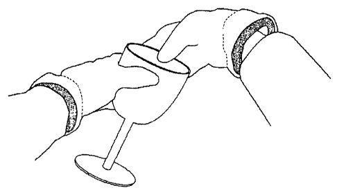
Figure 3 illustrates an exemplary usage of the current invention, showing a
user who has worn both gloves and is operating on a drinking vessel.
Figure 4 illustrates some five-finger embodiment that has been partially
turned inside out in order to show inner lining.
Figure 5 illustrates some disposable embodiment made from paper towel.
Figure 6 illustrates four cuts of fabric that are produced in one of methods
of
production of some embodiments described herein.
Figure 7 illustrates some six-finger embodiment of the current invention.
Figure 8 illustrates some mitten embodiment of the current invention.
Figure 9 illustrates a flowchart of some embodiment's method of operation.
Figure 10 illustrates cuts of fabric used to produce some embodiments of the
current invention.
Figure 11 illustrates same cuts as Figure 10, but with interdigital pieces
partially sewn in, so as to clarify their positioning.
Figure 12 illustrates some embodiment where sleeve of the glove extends
beyond the wrist area.
CA 02572394 2006-12-27
WO 2006/023451 PCT/US2005/029002
7
DETAILED DESCRIPTION OF THE INVENTION
In the following detailed description of the invention, numerous details,
examples and embodiments of the invention are set forth and described.
However, it
will be clear and apparent to one skilled in the art that the invention is not
limited to
the embodiments set forth and that the invention may be practiced without some
of
the specific details and examples discussed.
Some embodiments of the invention provide a moisture absorbent hand-
covering device that is in the form and shape of a glove for drying. In some
embodiments, the drying glove of this invention has a first outer layer and a
second
inner layer. The outer layer comprises at least one layer of material with
propensity to
absorb at least one type of liquid. In some embodiments, the second inner
layer
comprises at least one layer of material with propensity to repel at least one
type of
liquid. The outer layer absorbs the liquid for the purpose of removing it. The
inner
layer resists passage of the liquid, and thus protects the hand of the user
during
operation. In some embodiments, the liquid absorbed is water, and the liquid
repelled
is water.
Some embodiments of the invention provide a hand-covering device that is in
the form and shape of a glove for polishing. In some embodiments, the
polishing
glove has a first outer layer and a second inner layer. The outer layer
comprises at
least one layer of material that at least partially absorbs a polishing agent.
The inner
layer comprises at least one layer of material that at least partially repels
a polishing
agent. The outer layer at least partially absorbs the polishing agent for the
purpose of
applying it to the object being polished. The inner layer resists passage of
the
polishing agent, thus protecting the hand of the user during operation.
CA 02572394 2006-12-27
WO 2006/023451 PCT/US2005/029002
8
Some embodiments of the drying glove are produced in pairs, one for each
hand of a user. Some embodiments receive and cover hands of a user from
fingertips
to at least wrist area. In some embodiments, the drying glove has a sleeve
that starts
from substantially below the wrist area and extends above it. Some embodiments
provide a short sleeve that ends above the wrist area. Some other embodiments
provide a longer sleeve that extends up the user's arms beyond the wrist area.
Other
embodiments may be constructed differently. For instance, some embodiments
comprise only one layer. These embodiments do not provide the inner second
layer.
Some embodiments are made in one-size-fits-all configuration. Some other
embodiments are made as fitted gloves configured according to predetermined
hand
sizes.
Some embodiments are designed specifically for the purpose of drying kitchen
dishes and other household items, such as windows, kitchen cabinets, and
glassware.
Some embodiments are designed specifically for the purpose of polishing
objects, for
example silverware. Some of the polishing embodiments have two layers. The
outer
layer partially absorbs a polishing agent for the purpose of applying it to
the object,
where the inner layer repels the polishing agent to protect the hand of the
user. Some
embodiments are used to dry or clean automobile windows, windshields,
industrial
items, etc. Drying glove is a convenient tool for handling and drying objects
of any
kind with added security against dropping the object, and with reduced risk of
depositing unwanted fingerprints and smear marks. Further, the drying glove is
suitable for dusting objects of any kind.
Some embodiments provide an inner layer comprising of a moisture-resistant
or moisture-repellent material for protection of user's hands from moisture
and
wetness of the object being dried. During operation of this invention, drying
is done
CA 02572394 2006-12-27
WO 2006/023451 PCT/US2005/029002
9
with ease, while the object is securely held, and the user's hands are
protected from
the wetness, be it from water or other liquid. The inner layer in some
embodiments is
especially treated to repel a specific liquid, for example water, thus
protecting the
hands of the user from that liquid. Some embodiments include two layers, which
target a specific liquid to be absorbed by the outer layer, while being
repelled,
inhibited, or rejected by the inner layer. This targeting is done in several
ways, for
example, specialized fabric, specialized treating of fabric, etc.
Some embodiments are made from at least one layer of disposable moisture-
absorbent material, such as absorbent paper (i.e., paper towel). These
embodiments
teach a new disposable device for dexterous and easy liquid removal. Similar
to non-
disposable embodiments, disposable embodiments of this invention have various
forms (e.g., five-finger gloves, six-finger gloves, mittens, etc).
Several embodiments are described herein for drying dishes or other articles,
or for removing any type of liquid from objects or surfaces. One of ordinary
skill in
the art will realize that other embodiments of the invention may be used for
other
purposes.
I. CONFIGURATION
Some embodiments provide a device for covering a human hand where the
glove has at least one sheath for receiving a user's hand or fingers. Some
embodiments comprise at lease one layer made of some material or fabric
suitable for
special purposes of those embodiments.
Figure 1 and Figure 2 illustrate a drying glove of some embodiments of the
invention. Figure 1 presents the vertical view from the palmar side, and
Figure 2
presents the perspective view facing the hand entry aperture of the glove. As
shown
in these figures, the glove 100 is produced in the shape of a five-finger
glove. In
CA 02572394 2006-12-27
WO 2006/023451 PCT/US2005/029002
other words, the glove 100 has hand coverings with a separate sheath for four
fingers
and one thumb. The glove 100 has two layers. The outer layer 101 is moisture
absorbent. The inner layer, which covers inside of the outer layer and is not
visible in
these two figures, is moisture repellent. An elastic band 102 has been affixed
to about
the beginning of glove 100's sleeve 105 area to enable a snug fit. A trim 103
has
been sewn around the edges of the hand entry aperture to bind the layers
together and
provide more robustness. A loop 104 has been sewn to edge of the aperture, and
is
used to hang the glove 100 when not in use.
Figure 4 illustrates a glove 400 of some embodiment. The glove 400 is
similar to glove 100, but with the sleeve turned partially inside out in order
to
illustrate the inner layer 415. This figure presents two layers. The outer
layer 405 is
similar to the outer layer 101 of Figure 1. The inner layer 415 is presented
in Figure
4, but is not visible in Figure 1. Trim 410 is similar to trim 103 of Figure
1.
Some embodiments are configured in the shape of a five-finger glove that is
similar to the glove 100 of Figure 1, but has the thumb sheath placed in a
neutral
middle position with respect to dorsal and palmar surfaces. In these
embodiments, the
dorsal and palmar sides become indistinguishable. Therefore, each hand
covering can
be worn on either right or left hand. Each surface of glove can serve as
either palmar
or dorsal surface depending on which hand is placed in it. Glove 500 of Figure
5 and
a glove whose exploded layers are presented in Figure 6, illustrate some
embodiments of this configuration.
Figure 7 illustrates a glove 700 of some embodiment of the invention. The
glove 700 is configured in the shape of a six-finger glove. That is hand
covering with
a separate sheath for each finger, and two separate sheaths for thumb on
either side of
CA 02572394 2006-12-27
WO 2006/023451 PCT/US2005/029002
11
the hand covering. In this embodiment, each hand covering can be worn on
either left
hand or right hand, utilizing one or the other thumb sheath.
Still other embodiments are produced in the shape of hand covering which
encase the thumb separately and the other four fingers together, thus
producing a
drying mitten. Figure 8 illustrates such a mitten embodiment of the drying
glove.
This embodiment has two layers, an outer layer 805 and an inner layer 815. The
illustrated embodiment has an elastic band 810 around the wrist area to
tighten the fit
around the wrist area of the user. It also has a loop 820 so that the drying
mitten can
be hung when not in use. In this embodiment, thumb sheath has been placed
further
into the palmar surface in order to make the device more comfortable to wear
and
operate. In some other embodiments, thumb sheath is placed in mid-position
relative
to palmar and dorsal surfaces, thus rendering palmar and dorsal surface of
each mitten
indistinguishable. The latter embodiments can be worn on either hand.
As mentioned earlier, some embodiments are configured to fit any hand. In
other words, these embodiments are designated one-size-fits-all, and thus can
be used
by any user with any hand size. These embodiments are not fitted hand
coverings.
Other embodiments are configured as fitted covering for a hand. These
embodiments
are designed to predetermined glove sizes.
Some embodiments are made in one layer configuration. Some embodiments
are made in configurations of several layers. For example, some embodiments
are
made in a three-layer configuration where the outer layer is of moisture
absorbent
material, the middle layer is of moisture resistant nature, and the inner
layer is of a
material comfortable for skin to touch. Other embodiments may have
configurations
where each layer has a different nature and purpose than stated herein.
II. MATERIAL
CA 02572394 2006-12-27
WO 2006/023451 PCT/US2005/029002
12
As mentioned above, some embodiments of the current invention illustrated in
Figure 1, Figure 2, Figure 3, Figure 4, and Figure 8 illustrate some
embodiments
that are made of two layers, an outer layer and an inner layer. The material
used for
either of the two layers can be of any variety of natural or synthetic
fabrics, or a
combination thereof.
A. Outer Layer
In some embodiments, the outer layer is formed from a material with
propensity to absorb moisture. This moisture absorbent material can be any
type of
natural or synthetic fabric or material that has capacity to absorb liquid.
For example,
material for the outer layer may comprise cotton or terrycloth or absorbent
paper (i.e.,
paper towel) or any other wood pulp based material or any pile fabric or micro-
fiber
or waffle-weave or velvet or other natural fabric or other synthetic material
or
material to be invented or discovered in the future, or a combination thereof.
Some
embodiments use heavy terrycloth for the outer layer. Some embodiments use
absorbent paper (i.e., paper towel) for the outer layer. Main raw material for
production of this invention's outer layer is selected based on that
material's
propensity to absorb moisture and liquid. The main feature sought in the outer
layer
material is moisture absorbency.
In some embodiments, the outer layer is formed from a material that at least
partially absorbs a polishing agent. This material can be any type of natural
or
synthetic fabric or material. These embodiments comprise any of the material
mentioned in this section, or a specifically designed material, or a specially
treated
material, or a combination thereof.
Some embodiments are made from absorbent paper (i.e., paper towel). For
example, one such embodiment is illustrated in Figure 5. The material for
these
CA 02572394 2006-12-27
WO 2006/023451 PCT/US2005/029002
13
embodiments comprises absorbent paper (i.e., paper towel), heavy industrial
moisture
absorbent paper, or other wood pulp based material.
In some other embodiments, the dorsal and palmar portions of the outer layer
are made from different types of material. In other words, the palm portion
covering
the palm of the user is made of a different material than the back portion
covering the
back of the hand of the user. One of these different types of material, for
example the
material for the palmar portion, is moisture absorbent and the other is
abrasive. These
embodiments enable the user to perform drying, polishing, and scrubbing of an
object.
B. Inner Layer
In some embodiments, the inner layer is formed from a material with
propensity to inhibit moisture. This moisture repellent material can be any
natural or
synthetic fabric or material that has the capacity to repel, resist, inhibit,
insulate from,
or reject liquid. Some embodiments use waterproofing-treated polyester for the
inner
layer. Main raw material for production of the inner layer is selected based
on that
material's propensity to resist or repel liquid or moisture. For example,
material for
the inner layer may comprise rubber, nylon, any type of plastic, waterproofing
treated
polyester, vinyl, acrylic, rayon, other types of polyester, any other natural
or synthetic
material available now or to be invented or discovered in the future, or a
combination
thereof.
In some embodiments, the inner layer is formed from a material that resists at
least one type of polishing agent. This polishing agent repellent material can
be any
natural or synthetic fiber or material that has the capacity to repel, resist,
inhibit,
insulate from, or reject at least one type of polishing agent. This material
can be any
type of natural or synthetic fabric or material. The material for the inner
layer of
these embodiments may comprise any of the material mentioned in this section,
or a
CA 02572394 2006-12-27
WO 2006/023451 PCT/US2005/029002
14
specifically designed material, or a specially treated material, or a
combination
thereof.
Figure 1, Figure 2, Figure 3, Figure 4, and Figure 8 illustrate some two-
layer embodiments of the invention. A moisture-absorbent or moisture-retentive
material, as explained earlier, is used as the primary raw material for
production of the
outer layer 101. In some embodiments, a non-porous, moisture-resistant,
moisture-
repellent, or moisture-insulating material, as explained earlier is used for
the inner
layer 415. In some embodiments, an elastic band 102 is added substantially
about the
wrist area in order to tighten the fit around the wrist of the user and allow
a larger
aperture entry. The material for the elastic band is selected based on its
elasticity.
The material for the optional elastic band may comprise any of the raw
materials
explained above. Further, a trim 103 can optionally be included for added
protection
of edges, and for aesthetic appeal. A loop 104 can also be optionally added to
the
inner layer, the outer layer, or the trim. The loop can be used for hanging
the device
when not in use. The material for the trim and the loop comprises the inner
layer
material, the outer layer material, or other suitable material.
III. METHOD OF OPERATION
Some embodiments are used for drying dishes or other articles. Further, this
invention can be used for polishing dishes or other articles, performing auto
detailing,
or other personal or professional usage. In some embodiments, a user employs
this
invention for removing any liquid that may have accumulated in, on, or about
any
object or surface. The wetness or moisture that is targeted to be reduced or
eliminated
by some embodiments of this invention does not have to be water-based. Any
wetness of an object- or surface is reduced or substantially eliminated by
usage of
some embodiments of the current invention.
CA 02572394 2006-12-27
WO 2006/023451 PCT/US2005/029002
Some embodiments of the drying glove can be worn on one or both hands,
providing flexibility, ease, security, and comfort for the task of drying. In
addition,
some embodiments can be used for polishing dishes or other articles, or for
performing auto detailing. One method of drying operations of some embodiments
is
a fusion of usage of gloves in conjunction with usage of towels.
Figure 9 presents the flow of steps taken in normal operations of some
embodiments, where a user wants to dry or polish an object. Operation begins
with
step 905 where the user puts one glove on one hand. It continues with step 910
where
the user puts the other glove on the other hand. At the next step 915, the
user
determines whether the object is portable and should be picked up. If the user
decides
to pick up the object, he/she proceeds to pick it with one or both hands at
step 920.
This step is skipped should the user decides not to pick up the object.
The user then proceeds at step 925 to wipe or rub outer surface of one or both
gloves onto surfaces of the object. At the next step 930, the user decides
whether the
object has been sufficiently dried or polished. If the user decides that the
object is not
sufficiently done, he/she repeats step 925 until the object is done to the
user's
satisfaction. At the next step 935, if the user is handling a portable object,
he/she puts
the object at a desired location 940. At the next step 945, user decides
whether there
are other objects to be processed. If the user decides to continue, he/she
goes back to
step 915 above, and repeats the steps that follow it.
When the user decides to stop operating this invention, he/she removes the
gloves at step 950 that ends the operations. During the above operation of
some
embodiments of this invention, the user holds the target object securely with
one or
both hands. Furthermore, the user has usage of all ten fingers to reach
substantially
every corner and crevice of the target object.
CA 02572394 2006-12-27
WO 2006/023451 PCT/US2005/029002
16
IV. METHOD OF MANUFACTURE
In some embodiments, the glove is made from one layer of moisture absorbent
material. In some embodiment, such as those presented in Figure 1 and Figure
2, the
glove is produced in two layers. The outer layer is produced from moisture
absorbent
material, and the inner layer is produced from moisture resistant material.
I Figure 10 illustrates cuts of fabric that are made in process of
manufacturing
some embodiments. A material is chosen for the outer layer as explained in the
"Material" section. That material is then cut in shapes 1005, 1010, 1020,
1025, and
1030. The main portion 1005 has a hole 1015 cut out of it. Later in the
process, a
thumb sheath is made from cut 1010 and attached to portion 1005 at edges of
the hole
1015. Top sections of cut 1005 form sheaths for the fingers. To make the main
body
of the outer layer, cut 1005 is folded along an imaginary vertical line 1066
in its
middle. Once folded, section 1038 is aligned with section 1040 in preparation
for
making a sheath for index finger. Similarly, section 1036 is aligned with
portion 1042
in preparation for making a sheath for middle finger. Portion 1034 is aligned
with
portion 1044 in preparation for making a sheath for ring finger. Portion 1032
is
aligned with portion 1046 in preparation for making a sheath for little
finger.
Cuts 1020, 1025, and 1030 provide extra fabric for interdigital spaces between
finger sheaths. These cuts are sewn in along edges between portions for finger
sheaths in order to provide more fabric for interdigital space. First, these
cuts are
folded in half, and then they are inserted in the interstice between sections
designated
for finger sheaths. Finally, they are sewn to edges of those sections. Figure
11
presents a partially sewn view of Figure 10. Cuts 1020, 1025, and 1030 are
referenced by the same numbers in Figure 11. In Figure 11, one length of cuts
1020,
1025, and 1030 edges have been sewn, and the other edges are not yet sewn.
When
CA 02572394 2006-12-27
WO 2006/023451 PCT/US2005/029002
17
completed, the extra fabric provided in this manner allows finger sheaths to
better
conform to the shape of fingers, and thus be more comfortable for the user.
For
instance, cut 1020 covers the interdigital space between index finger and
middle
finger. The edges of portion 1020 are sewn to the edges of adjacent portions
1038,
and 1036. They are also sewn to the edges of 1040, and 1042 which are
counterparts
of 1038, and 1036. In other words, each end point of piece 1020 is aligned
with, and
sewn to, one of points 1050 and 1052. As a result extra fabric is provided for
interdigital space between index and middle fingers. The extra fabric allows
the
finger sheaths to be more spacious and thus relaxes the fit in the interstice
between
index and middle fingers.
Similarly the cut 1025 covers the interdigital space between middle finger and
' ring finger. The edges of 1025 are sewn to edges of portions 1036, 1034,
1042, and
1044 in a manner substantially similar to cut 1020. This provides extra fabric
thus
relaxing the fit for interdigital space between ring and middle fingers. In a
similar
manner, cut 1030 is sewn along edges between portions 1032, 1034, 1044, and
1046
thus relaxing the fit between ring finger and little finger. The outer most
edges of
1050, that is edges 1054 and 1056, are aligned and sewn together to complete
the
hand covering. The lower edge of 1005, namely edge 1058 is not sewn and thus
provides an entry for receiving a hand.
Cut 1010 makes a thumb sheath. It is folded along the imaginary vertical line
1048. Cut 1010 is then sewn together around its edges to an extent sufficient
to
provide a thumb sheath. Lower edges of cut 1010 are sewn to around edges of
hole
1015. Elastic band 1035 is sewn around the wrist portion of the resulting
device to
enable a tighter fit. The lower half of Figure 10 shows cuts similar to those
explained
above. These cuts are somewhat smaller in size than cuts shown in top portion
of
CA 02572394 2006-12-27
WO 2006/023451 PCT/US2005/029002
18
Figure 10. They are made from the fabric of choice for the inner lining. Cut
1062
forms the main body of the inner layer. Cut 1060 forms the thumb sheath of the
inner
layer. There are also three interdigital cuts corresponding to their outer
layer
counterparts. Process of sewing the pieces for the inner lining is
substantially similar
to that explained for the outer layer. Once both layers are ready, the inner
lining is
inserted into outer layer and is sewn along the edges. Alternatively, the
inner lining
cuts are matched to outer layer cuts from the beginning of the process and
sewn
together along all edges at the same time. In this embodiment, a loop 1064 is
sewn to
the inner layer material. Alternatively, the loop can be sewn to the outer
layer, or
both the inner layer and the outer layer. The loop is used to hang the drying
glove
when not in use.
The present invention can be made of different types of material as explained
in "Material" section of this document. Each device may be made of only one
layer
of fabric, or more than one layer of fabric where each layer of fabric
satisfies a
different purpose, or performs a different task. Some embodiments of the
present
invention, such as the one presented in Figure 10, have an inner layer to
insulate the
hands of the user from moisture and/or other external substances that may seep
through the outer layer.
Some embodiments of the present invention are built as follows. The fabric of
choice for the outer layer is cut in the form of a human hand. This cut is
done a total
of four times, thus producing two pairs of cuts, all in the shape of a hand.
Then, the
fabric of choice for the inner layer is cut similarly to above, but smaller.
This
produces two pairs of cuts from the inner layer material in the shape of a
hand.
Figure 6 illustrates one of the pairs for the outer layer, and one of the
pairs for the
inner layer. Cuts 605 and 620 are made from the outer layer material. Cuts 610
and
CA 02572394 2006-12-27
WO 2006/023451 PCT/US2005/029002
19
615 are made from the inner layer material. As Figure 6 illustrates, the
aforementioned cuts have sections that form the finger sheaths. All cutting
referenced
in methods of manufacture can be done in a variety of ways using scissors,
blades,
machinery, or other means.
After the cuts are made, each corresponding pair is adhered together at around
their edges. Cuts 605 and 620 are adhered together to form the outer layer.
Cuts 610
and 615 are adhered together to form the inner layer. The wrist side edges of
corresponding cuts are not adhered together, thus providing an aperture for
entry of a
hand. The inner layer is inserted into the outer layer such that each finger
sheath of
the inner layer enters and is substantially coextensive inside the
corresponding finger
sheath of the outer layer. The outer layer and inner layer are then adhered
together.
Cuts 605 and 620 present extra pieces of fabric that have been sewn into the
wrist end
of each cut. These pieces are sewn together to create a loop. In some
embodiments,
creation of the loop is optional. In some embodiments, the two layers of edges
of
hand-entry aperture just created are sewn together in order to secure the
inner layer to
the outer layer. In some embodiments, a trim is sewn to around the hand-entry
aperture to further secure it.
In some embodiments, the adhering and affixing mentioned in methods of
manufacture are done by means of one or more of the following: sewing,
stitching,
stapling, gluing, hot pressing, or other suitable method. Figure 6 presents
cuts that
make one glove. Attaching the other two pairs of cuts produced above creates a
second glove. Then, two devices with pockets for receiving a pair of human
hands
are created. In some embodiments produced in this manner, the thumb sheath is
reversible, thus each glove can be worn on either a right hand or a left hand.
CA 02572394 2006-12-27
WO 2006/023451 PCT/US2005/029002
When several layers of fabric are used, layers are attached together in
different
manners. The attaching of layers can be done solely at the edge of the
aperture, or
layers of fabric can be attached together along finger sheaths as well. Yet in
other
embodiments, these layers of fabric are attached both at the edge of the
aperture, and
along seams where feasible and practicable. In embodiments where more than one
layer of moisture-absorbent material is used, all layers may be adhered
together along
all seams. Alternatively, these layers may be adhered only at some points
along their
surfaces or seams sufficient to keep them together. In some embodiments of
this
invention as illustrated in Figure 1, a trim 103 is adhered to around the edge
of the
aperture of the device in order to protect the edge by adding robustness and
reducing
wear and tear, as well as add aesthetic appeal. Some embodiments have a loop
104
attached to each glove to facilitate hanging when the device is not in use.
Some embodiments employ ergonomic design principles to arrange each
finger sheath in a more comfortable position. For example, thumb sheath can be
cut
and sewn further into the palmar portion thus providing a more comfortable fit
and
grip for user as explained in Figure 10 earlier. Yet some other embodiments
position
the thumb sheath such that it is reversible, (i.e., make glove wearable on
either a right
hand or a left hand as explained previously). Some of these embodiments with
reversible thumb sheath are illustrated in Figure 5 and Figure 6.
Alternatively, a
finer production methodology of any kind known to a person skilled in the art
of
glove making can be utilized.
Some embodiments are produced without seams. That is, the outer layer is
produced in one piece of material as part of a manufacturing process.
Similarly, the
inner. layer is produced in one piece of selected material as part of a
similar
manufacturing process. The inner layer is then inserted into the outer layer
and
CA 02572394 2006-12-27
WO 2006/023451 PCT/US2005/029002
21
adhered to it at one or more locations. Other embodiments are produced by
cutting
material selected for the outer layer from a flat sheet of material according
to a
selected glove configuration and design. This is followed by cutting material
selected
for the inner layer from a flat sheet of material according to same or similar
glove
design as the outer layer. Then select edges of the inner layer are cohered
together to
produce pockets for receiving hand. The next step is to insert the inner layer
inside
the outer layer and fasten them together by adhering in select locations. In
some
embodiments finger sheaths are produced separately from the rest of the
device.
Then, the finger sheaths are attached to the hand covering in a second step.
In some embodiments, such as those illustrated in Figure 1 and Figure 10, the
inner layer is manufactured to be somewhat smaller than the outer layer so
that it fits
inside the outer layer with ease. Further, these embodiments have an inner
layer with
a snugger fit. In addition, some embodiments provide a larger outer layer with
more
fabric to enable absorption of more liquid.
In some embodiments, the inner layer is longer than the outer layer.
Therefore, in these embodiments, the inner layer extends above and beyond
wrist area
to protect more of user's arm. In yet other embodiments, the inner layer
extends
above and beyond the elbow area of the user. In some other embodiments, the
outer
layer is longer than the inner layer. In these embodiments, the inner layer
ends at
about the wrist area, whereas the outer layer extends beyond wrist area to
about elbow
area of user's arm. In other embodiments, the outer layer extends above and
beyond
elbow area. These embodiments provide a large outer surface for the job.
Conversely, in some embodiments, the inner layer is longer than the outer
layer. In these embodiments, the outer layer ends at about the wrist area,
whereas the
inner layer extends beyond the wrist area of the user to about the elbow area.
In some
CA 02572394 2006-12-27
WO 2006/023451 PCT/US2005/029002
22
embodiments, the inner layer extends above and beyond the elbow area of the
user.
These embodiments provide a larger inner layer for expanded protection of the
user's
hand and arm.
As mentioned previously, some embodiments have varying sleeve sizes.
Figure 12 illustrates an embodiment where both outer and inner layers coextend
beyond the wrist of user to about the elbow area. In other embodiments both
outer
and inner layers extend beyond the elbow area of user's arm to provide further
utility
for specialized jobs.
Several embodiments of the current invention are produced with varying
structural specifications in order to satisfy different needs. For example,
some
embodiments are produced from only one layer of moisture absorbent material
without the inner layer. Some embodiments are made with two layers, one outer
layer
and one inner layer. Materials for the inner layer comprise non-absorbent, non-
porous, moisture-insulating, moisture-resistant, or moisture-repellent
material.
Purpose of the inner layer is to protect the inner space of the glove from the
material
coming in contact with outer layer, and to protect the user's hand. Yet
another
embodiment is made of several layers of material, possibly with an additional
inner
lining added for comfort. In some embodiments, the outer layer is made from
several
moisture-absorbent materials in order to enhance absorbency qualities of the
current
invention. A low cost embodiment is made of at least one layer of moisture
absorbent
paper (i.e., paper towel), hence producing a drying glove similar to the one
illustrated
in Figure 5.
Hence, the reader can readily see that some embodiments of the drying glove
of this invention can be used to dry objects and articles in the kitchen,
home, garden,
workplace, or elsewhere. It is easy and intuitive to use. It is simple and
CA 02572394 2006-12-27
WO 2006/023451 PCT/US2005/029002
23
straightforward to manufacture. It enhances the security of the job of drying
by
means of allowing the user usage of both hands for the job at hand. It
simplifies the
job of drying by removing the risk of depositing fingerprints; smear marks, or
other
undesirable marks on the target article.
Several objects and advantages of some embodiments of the invention are
enumerated here. However, objects and advantages are not limited to those
mentioned. Further objects and advantages are to provide a glove that is used
easily
and conveniently to dry or polish any object, without depositing fingerprints
or smear
marks on the object, and to perform the job with security. A glove which is
simple
and inexpensive to manufacture; which is used to more conveniently perform
other
work that is usually done with a towel or a piece of cloth; and which obviates
the need
to use a simple rag with all of its shortcomings. Another object is to
provide, in some
embodiments of the current invention, a paper-towel drying glove made of
absorbent
paper or absorbent industrial paper material that performs all the
aforementioned
tasks, yet is cheaper and lighter. Still further objects and advantages are
apparent
from the description and drawings of some embodiments of the invention.
However,
objects and advantages of this invention are not limited to those enumerated
in this
document, and will be apparent to anyone with ordinary skill in the art.
As the attached drawings illustrate, the drying glove is simple in design, yet
novel and original in purpose, as well as method of operation. While the
present
invention has been illustrated and described as embodied in a glove for
drying,
however, it is not limited to the details explained. It will be understood
that various
omissions, modifications, substitutions and changes in the forms and details
of the
device illustrated and its operation can be made without departing in any way
from
the spirit of the present invention.
CA 02572394 2006-12-27
WO 2006/023451 PCT/US2005/029002
24
Without further analysis, the foregoing will so fully reveal the gist of the
present invention that others can, by applying current knowledge, readily
adapt it for
various applications without omitting features that, from the standpoint of
prior art,
fairly constitute characteristics of the generic or specific aspects of this
invention.