Note: Descriptions are shown in the official language in which they were submitted.
CA 02572434 2006-12-28
WO 2005/005009 PCT/US2004/021267
Dissociation of Molecular Water Into Molecular Hydrogen
Background of the Invention
S It is well documented in the field of exploration and production of fossil
fuels that
worldwide oil reserves are finite and being rapidly depleted. ~i1 production
in the United States
reached a peak circa 1970 and is rapidly declining. Outside the United States,
it is presently
believed that peak oil production will reach a climax in approximately ten to
fiileen years.
However, despite knowledge of the finiteness of the known reserves, demand for
oil
production and consumption continues to escalate due to increasing demands fox
energy within
and outside the United States. Accordingly, despite any short-term price
fluctuations in the
commodity markets, it is expected that the price of oil will continue to
escalate as known oil
reserves become increasingly scarce. Eventually the price of oil will become
too great to provide
reasonably priced energy to fuel the global economy, thereby resulting in
severe economic
contraction of worldwide output of goods and services.
In addition to the increase in oil prices relating to the increasing scarcity
of this commodity
in view of increasing demand, the majority of known oiI reserves are located
in countries that are
politically unstable. A government or cartel hostile to world economic growth
could hold
industrialised countries ransom to its oil by refusing to export its oil or
chargixig ludicrously high
prices. Sudden instability of coil production or price due to such hostilities
is forecast and
modeled to cause great economic rifts in our society. It is therefore
important that we increase
our reliance and resources on sources of energy that are readily available and
renewable.
~ther concerns regarding the use of fossil fuels are related to environmental
factors. For
example, the burning of fossil fuels produces carbon dioxide (C02) and smog
producing
compounds, such as unburned hydrocarbons and oxides of nitrogen, which are
generally released
into the atmosphere. It is known that increasing concentrations of C~2 in the
atmosphere have
resulted in climatic changes, notably global warming. It is further been
predicted that global
warming may also eventually cause severe rifts in the global society through
the loss of arable
land nceded to feed an ever-increasing global population. Furthermore, global
warming is
further causing melting of polar ice caps, thereby raising sea levels
rcsulting in further loss of
land for increasing populations.
-I-
CA 02572434 2006-12-28
WO 2005/005009 PCT/US2004/021267
One such source of energy that is readily abundant and renewable is hydrogen.
On a
weight basis, hydrogen possesses three times more energy than an equivalent
weight of gasoline.
There are several known methods of producing hydrogen, for example, coal
gasification, partial
oxidation of oil, steam methane reforming, and biomass gasification, among
others. Although
these methods have been shown to be efficacious in the generation of hydrogen,
a significant
disadvantage and limitation in each of these methods is the co-production of
carbon dioxide,
which as discussed above is a leading cause of global warming.
An alternative process technology that does not have carbon dioxide as a
byproduct is the
electrolysis of water. Nigh purity hydrogen and oz~ygen can be produced using
a relatively
simple electrolysis method. However, a significant disadvantage and limitation
of electrolysis is
the high electrical power requirements needed to split water into constituent
elements of
hydrogen and oxygen. Ivlany factors in the electrolysis method contribute to
these power
requirements.
For example, since water possesses a high dielectric constant, the resistance
in the current
path between the submersed electrodes is high. In addition, there is a mass
transfer resistance at
the electrodes due to the abrupt disruption of the electrolyte at the
electrode surface from the
evolution of gas. This disruption also increases the resistaa~ce to the flow
of elect~rieal energy.
Furthermore, the active surface area of the electrodes limits the electrolysis
process.
Accordingly, a need exists to overcome these inherent disadvantages and
limitations of
electTOlysis to split water into its constituent elements of hydrogen and
oxygen.
Water vapor discharges have been investigated by scientists for the purpose of
understanding the reaction mechanisms of chemical reactions. The intermediates
or free radicals
that are formed during the reaction were the main subject of interest in the
historic literature.
Another interest in the pursuit of water decomposition was to fmd a process of
generating
hydrogen peroxide.
An early attempt (H.C. Urey and G.I. Levin, Journal of the American Chemical
Society,
3290-3293, Vol. 51, November, 1929), at understanding the reactions in
dissociated water by
the Wood's tube was the discovery that water vapor under the influence of an
electric discharge
-2-
CA 02572434 2006-12-28
WO 2005/005009 PCT/US2004/021267
dissociated water into hydrogen atoms and hydroxyl free radicals. They noted
that the product
gas consisted of 2!3 the amount in hydrogen for the conditions that were run
in the experiments.
The paper does not illustrate any process conditions or the method of analysis
of the gas mix.
They also detected hydrogen peroxide in the water condensed in the trap. They
attributed the
excess hydrogen from the intermediate decomposition of the hydrogen peroxide
product and not
directly from the water vapor. They give support to this assertion by noting
that past
observations state that hydrogen peroxide is formed first and then further
decomposed to simpler
species. Experiments were conducted to deternaine the presence of hydrogen
atoms and
hydroxyl radicals, which was confirmed by the activity of the gas. They noted
the products from
the water vapor discharge were more active than if only hydrogen atoms were
present. There
was no conclusive proof of the existence of these species as cautioned by the
Authors.
Another group of investigators (R.A. Jones, W. Chin and M. ~enugoplan, The
Journal of
physical Chemistry, volume 73, number 11 page 3693-3697, November 1969) were
motivated to
I S investigate the formation of hydrogen peroxide using a vacuum microwave
discharge. They
investigated a range of process conditions using water vapor as the reactant
and trapping the
products of dissociation in a cold trap at very low temperatures. They
determined the yield of
hydrogen peroxide under varying conditions.
P,J. Frie1 and I~.A. I~reiger, Journal of the American Chemical Society, vol.
~0, p. 4210 -
421 ~, 195 ~ investigated the recombination of the high voltage discharge
products of water vapor.
They used various surfaces in order to elect the recombination reactions and
determine the final
product composition. They principally focused on using the surface of silica
gel to study
recombination reactions. They discovered that silica gel did not catalyze the
recombination of
hydrogen atoms. They speculated that a surface was an active intermediate in
the subsequent
reactions. The recombination reaction was accompanied by a temperature
increase and a green
Luminescence on the surface of the gel. It was noted that under these
conditions the principal
products of the reaction was H2 and 02. The reactions were conducted in a
moderately high
vacuum (<300 millitorr) and extremely low flow rates (<20 nullimoles/ hour).
In addition,
reactions of the water vapor discharge products in a liquid air trap were
analyzed and studied.
Hydrogen peroxide, water and hydrogen and oxygen were formed. The predominant
product
were water and hydrogen peroxide as well as hydrogen. Most further studies
centered about
optimizing the formation of hydrogen peroxide or studying the OH free radical.
-3-
CA 02572434 2006-12-28
WO 2005/005009 PCT/US2004/021267
On January 2S, 2003, George W. Bush, President of the United States of
America,
delivered to Congress the constitutionally mandated State of the Union
address, available at
http://www.whitehouse.gov/news/releases/2003/OI/20030128-l9.html. In this
address, the
President set forth a goal to promote energy independence for the country
while dramatically
improving the environment. Mr. Bush asserted in the address that "[I]n this
century, the greatest
environmental progress will come about ... through technology and innovation"
and implored
Congress to "protect our environment in ways that generations before us could
not have
imagined."
In the same address, the President offered a proposal to Congress to authorize
X1.2 billion
in research funding top place the Ltnited States at the forefront of
developing hydrogen powered
automobiles in which hydrogen is reacted to oxygen to generate the energy to
power the
automobile, producing only water as a by product and not exhaust fumes. Mr.
Bush recognized
this innovation would "make our air significantly cleaner, and our comitry
much less dependent
on foreign sources of energy."
Subsequent to this address, it was reported in "Bush Hydrogen Initiative Fuels
Debate,"
http://wvaw.cnn.com/2003/ALLP~IdfTICS02/07/hydrogen.vision.ap/, Friday,
Febru~.ry 7, 2003,
that most of the major automobile companies doing business in the ITnited
States already have
operational hydrogen powered fuel cell vehicle prototypes being road tested.
In the cited report,
the spokespersons for these companies express optimism that hydrogen powered
fuel cell
vehicles could be available to consumers within a decade, a timetable even
more aggressive than
the one proposed by the President. However, as reported in this article, this
optimism is
tempered by a cautionary note that "a hydrogen distribution system has. not
fret even begun to be
developed."
Despite the expressed enthusiasm presented by the automobile manufacturers,
the
President's goal of developing hydrogen powered automobiles was nonetheless
met by others
with stinging criticism. To quote one such criticism, "[W]hat Bush didn't
reveal in his
nationwide address, however, is that his administration has been working
quietly to ensure that
the system used to produce hydrogen will be as fossil fuel-dependent -- and
potentially as dirty --
as the one that fuels today's STJ~s. According to the administration's
National Hydrogen Energy
Roadmap, drafted last year in concert with the energy industry, up to 90
percent of all hydxogen
will be refined from oil, natural gas, and other fossil fuels -- in a process
using energy generated
_q._
CA 02572434 2006-12-28
WO 2005/005009 PCT/US2004/021267
by burning oil, coal, and natural gas. The remaining 10 percent will be
cracked from water using
nuclear energy." See, 1 'Bush's Hydrogen Fuel Comes From 4i1...," Barry C.
Lynn, Mother
Jones, March 6, 2003, published by Rogue Independent Media Center,
http:l/rogueimc.org12003/06/808.shmtl. ,
The article, from which the quote set forth immediately above has been
obtained, states
that the administration's propos~.l to obtain hydrogen from fossil fuels would
effectively
eliminate the benefits offered by using hydrogen as a fuel for automobiles
since the process of
producing hydrogen from fossil fuels still vv~uld result in the release of
carbon dioa~ide, the
primary cause of global warming, into the atmosphere and continue this
country's dependence
on fossil fuels, most of which comes from imported ail. In this article
criticism is also directed
to the major oil companies seeking to protect their dominance in energy
resources through
lobbying efforts to affect administration policy and congressional legislation
and through
acquisitions o~'small research oriented companies seeking to produce hydrogen
from renewable
energy sources. Should the oil companies be success~ix~ in protecting their
dominance, the article
infers that even with a hydrogen economy, the country will remain dependent of
foreign sources
of oii for generations to come.
Although the cited article, along with its criticisms, makes inference that
water is a
preferred source for hydrogen, it further states that the known technologies
for breaking water
molecules into its constituents of hydrogen and oxygen in commercially usable
quantities are
extremely energy intensive, as in electrolysis in which an electric current
between an cathode
and an anode immersed in water ionises the water molecules such that the
hydrogen and oxygen
ions respectively migrate to the anode and cathode. The article cites the
preferred source for
such energy as nuclear power plants, which the article states are also
unacceptable due to the
ecological impacts such plants are known to cause. Accordingly, the article
postulates that only
10% of the total hydrogen will be produced form water.
Accordingly, it is seen that the prior art, even with all the criticisms
targeted at such art,
envisions fossil fuels, being a fuel source rich in carbon and hydrogen, as
the primary source of
hydrogen production in the foreseeable future without regard to the necessity
of removing such
carbon in the form of carbon dioxide. Without containment, the carbon dioxide
will further
contribute to global warming. The use of fossil fuels for a source of hydrogen
will cause even
greater demand on the known reserves, which are being rapidly depleted.
-5-
CA 02572434 2006-12-28
WO 2005/005009 PCT/US2004/021267
Therefore, with the known prior art, the President's stated goal of energy
independence
and an improved environment are not met. In fact, adopting the apparatus and
processes of the
known prior art would continue the country's dependence imported oil and
further accelerate the
rapid depletion of known reserves of oil and cause further environmental
degradation.
More recently, California Governor Arnold Schwarzenegger, in the State of the
State
address delivered 3anuary 7, 2004, called for the development of a "hydrogen
highway." The
hydrogen highway ~chwar~enegger referred to in his speech is a highway of
fueling stations
located along major interstate highways, according to a state environmental
protection agency
official.
In yet another article that has been reported at
http://story.news.yahoo.com/news'~tmpl=story8~cid=2~9~zncid=2898~e=7~u=/ibsys/2
0040109/l0
kcra11949~44, environmental Secretary Terry Tamminen is the man behind
Schwar~enegger's
plan to make the hydrogen highway a reality. He says there is a good reason it
doesn't exist
already. "The energy companies don't want to make hydrogen fueling stations
because there are
no vehicles and the vehicle-makers don't want to produce vehicles because
there are no fueling
stations. So we are trying to break that chicken or egg cycle,.' he said.
It was the stated goal of the California governor to have, by the year 2010,
nearly 200
hydrogen fueling stations up and running. Tarnminen says it will take about
$100 million in
public and private dollars to help companies build them.
At the University of California at Davis, those who have been leading the
world's research
on hydrogen cars axe glad to see the governor fmaliy jump starting the mass-
production process.
CJC D~.vis's Dan Sperling told the station, "It will be good for the company
eventually, but it will
be good for society. So, we need the government to provide some rewards."
Prototype mechanics
say once mass-produced, a hydrogen car's peppy performance will reward
drivers, too.
Summary of the Invention
Applicant's invention, as set forth in the above-identified application, meets
the President's
goal by furthering environmental progress through technology and innovation
and also protects
-6-
CA 02572434 2006-12-28
WO 2005/005009 PCT/US2004/021267
our environment in a novel way that generations before us could not have
imagined. Applicant's
invention further addresses the above stated concern of the automobile
industry relating to the
lack of a hydrogen fuel infrastructure in that Applicant's claimed processes
are scalable allowing
for the efficient production of hydrogen on a small local scale, such as in
the home ox vehicle,
while large installations could produce quantities suitable for commercial
distribution. Whereas
current fossil fuel technologies rely upon an extensive global infrastructure
from extraeting the
raw fuel, whether coal, oil or natural gas, from the ground, through refining,
transporting and
storing of the raw fuel, intermediaries and byproducts up to the ultimate
delivery of the final
fuel product to consumers, the methods of the present invention do not rely on
the construction
of such far flung infrastructure but may be practiced at the point of use of
the produced
hydrogen. Accordingly, Applicant's invention also enables the goal of the
California governor
by allowing ~. hydrogen infrastructure to be developed that obviates the
global infrastructure of
fossil fiiel delivery.
Applicant's invention also negates the above cited criticisms of extracting
hydrogen from
fossil fuels since Applicant's invention does not rely on fossil fuels as the
source of hydrogen.
moreover, Applicant's invention may rely on renewable energy sources and
wasted energy of
conventional energy production as the source of energy to extract the hydrogen
from molecular
water.
It is taught, through Applicant's disclosure in the present application, that
hydrogen can, be
extracted from water, the preferred source of hydrogen, using a novel process
that is highly
efficient and not as energy intensive as electrolysis. In fact Applicant's
disclosure envisions
renewable and recyclable resources as the source of energy to produce hydrogen
for molecular
water thereby ultimately removing dependency from fossil fuels altogether.
According to the present invention, molecular water, preferably in the form ~f
high
temperature steam or water vapor, is introduced into a radiant energy transfer
chamber. The
radiant energy is of sufficient energy to excite the water molecules thereby
causing the
dissociation thereof into the constituent molecular elements of hydrogen and
oxygen. To prevent
recombining of the constituent molecular elements, the hydrogen and oxygen are
separated from
each other. Various methods may be employed to effect this separation. Once
separated, the
molecular components are prevented from recombining with each other or with
other elements
CA 02572434 2006-12-28
WO 2005/005009 PCT/US2004/021267
by using standard separation techniques normally employed for separating
dissimilar gaseous
species.
These and other objects, advantages and features of Applicant's invention will
become
readily apparent from a study of the following Description of the exemplary
Preferred
Embodiments when read in conjunction with the attached drawing and appended
Claims.
brief Dcscripti~n ~f the Drawing
IO Fig. 1 is a perspective view, partially broken, of a radiant energy
transfer apparatus useful
to practice the present invention;
Fig. 2 is a block diagram of a radiant energy transfer system constructed
according to the
principles of the present invention; and
IS
Fig. 3 is a block diagram of a magneto hydrodynamic system useful to replace
the turbine
and generator of Fig. 2.
description ~f the ~nventi~n
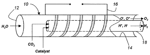
kith reference to Fig. l, there is shown a radiant energy transfer reactor 10.
The reactor
10 includes a first portion 12 adapted to receive water molecules, a second
portion 14~ at which
the constituent components of the dissociated water molecules may be further
separated and
removed, a coil 16 to which electrical energy is applied to develop an
electromagnetic field
within the reactor 10 generally defining a reaction zone intermediate the
first portion 12 and the
second portion 14 of the reactor 10.
It is to be understood that the structure required to develop the
electromagnetic field need
not be limited to the coil 16 as seen in Fig. 1, Any structure that is capable
of developing an
electromagnetic field in the reaction zone of the reactor 10 is contemplated
to be an equivalent
structure. For example, in priority application United States Serial No.
10/632,708, incorporated
herein, various structures are disclosed that are useful to induce the
electromagnetic field in the
reaction zone of the reactor 10. For example, instead of the coil 16 as shown
herein, the
electr~magnetic field within the reaction zone of the reactor 10 can be
developed by applying
_g_
CA 02572434 2006-12-28
WO 2005/005009 PCT/US2004/021267
electrical energy across radially opposed field plates, axially spaced field
rings, or by a
waveguide, among others, all as shown in the above referenced application.
Several examples
are set forth below. More generally, several variations of radiant energy
transfer reactors that
may be used to practice the present invention are described below.
It is to be initially understood that the construction of any such reactor is
not to be limited
to the specific examples shown therein, butt that any reactor that transfers
energy to molecular
water, as described in greater detail hereinbelow, is contemplated by the
scope of the present
invention. Accordingly, the following description is not to be deemed limited
to the exemplary
reactor herein described.
It is known that molecules absorb energy throughout the entire electromagnetic
spectrum.
Furthermore, the energy can be differentiated according to the mode of
absorption. For example,
the absorbed energy may increase or decrease any of three kinetic modes of
motion of the
molecule, these modes being rotational, vibrational and translational motion.
Each kinetic mode
may further be associated with specific wavelengths or frequencies of the
absorbed radiation,
such that the rotational, vibrational and translational energies of the
molecule will have its own
characteristic wavelength or frequency. Furthermore, at the point of
dissociation of the
molecular bond, the corresponding energy will have a characteristic frequency
or wavelength for
each of these kinetic modes.
In addition to absorption to excite any or all of the three kinetic modes set
forth
immediately above, electromagnetic energy at selected wavelengths may also be
absorbed t~
excite the electronic mode of the molecule. Excitation of the electronic mode
causes electrons in
one orbital of the molecular bond to be excited into a higher energy orbital.
With sufficient
energy absorption, the molecular bond will be overcome thereby allowing
dissociation of the
molecule into its constituent parts.
Water molecules, in particular, absorb greater amounts of electromagnetic
energy having
wavelengths in the ultraviolet, infrared, microwave or radio frequency
spectrum. The ~'H bond
of the water molecule has a characteristic frequency or wavelength based on
the kinetic or
electronic modes described above. Accordingly, at specific wavelengths or
frequencies within
this spectrum the ~H bond will dissociate, in any one or combination of the
kinetic and
electronic modes, providing that the energy of the electromagnetic energy at
the frequency of
-9-
CA 02572434 2006-12-28
WO 2005/005009 PCT/US2004/021267
dissociation is sufficient to overcome the energy of such bond. For example,
one such frequency
will excite the translational mode of the water molecule, and with sufficient
energy, cause the
molecule to dissociate. tether frequencies will of course excite the other
modes.
The dissociation of the ~H bond will result in the formation of hydrogen (H)
and oxygen
(~) species. It is necessary that these species be separated so that they do
not recombine with
each other to return to molecular water, but combine with their own species
such that hydrogen
gas (H2) and oxygen gas (~~) result.
The above referenced application also discloses several types of apparatus and
techniques
t~ effect this separation. Accordingly, the following description is not to be
deemed limited to
the exemplary separation herein described. Accordingly, any of various forms
of membranes,
converging-diverging nozzles, electromagnetic field or rotational plasma
centrifugation may be
used.
For example, the apparatus of Fig. 1 includes a membrane 1 ~ withixt the
reaction ,one
intermediate the i'xrst portion 12 and the second portion l~~ of the reactor
10. As described in
greater detail below, the membrane 1 ~ has porosity such that it is permeable
to the hydrogen
species but eontains the oxygen species of the dissociated water molecules.
Preferably, the water molecules introduced into the reactor 10 are in the form
of high
temperature steam, such that energy input into the reactor 10 can be primarily
utili~d for the
absorption at the specked frequency for dissociation. In this regard, various
sources of high
temperature steam can be used such that energy used fro dissociation is not
consumed tb develop
the steam.
For example, geothermal steam may be used both as a source of the water
molecules for
the reactor 1 p, and for developing, using a conventional steam turbine and
generator, some or all
of the electrical energy to develop the primary electrical energy to be
converted to the high
frequency energy for application to the coil 16. Additionally, steam for such
purposes can be
developed using naturally occurring hot dry rocks and abandoned oil and gas
wells, such that
water introduced into these systems exists as high temperature steam.
Furthermore, solar and
wind sources can also be used to provide the energy fox the reactor 10 and for
developing the
high temperature steam.
-10-
CA 02572434 2006-12-28
WO 2005/005009 PCT/US2004/021267
Also as described in the above referenced application, coal, oil, natural gas
and nucleax
fueled power plants can also provide the primary electrical energy for the
reactor 10 with the
waste steam from the steam turbines and cooling towers being used as the
source of water
molecules for the reactor 10. Accordingly, it is seen that the present
invention may supplement
the use of fossil fuels and obviate their use in accordance with specific
applications. Also, the
hydrogen production can be fixed to existing locations of power plants and
distributed sites
where a source of hydrogen is needed.
As described above, the electromagnetic field developed within the reaction
zone of the
reactor 10 remains the primaxy source to effect dissociation of the molecular
water. It is
contemplated~by the present invention that other sources of energy for
dissociation may be used
in addition thereto to enhance overall efficiency of the dissociation process.
For example, as the hydrogen species exits the reaction zone from within the
membrane
1 ~, it recombines into hydrogen gas, or H2. V~hen this recombination occurs,
electromagnetic
energy in the ultraviolet spectrum is emitted. Since water molecules are
absorptive of this
energy, such emitted energy may be "piped" back to the incoming stream of
super heated steam
to assist in the dissociation. For example, the membrane 1 ~ may be
constructed of a material
transparent to ultraviolet electromagnetic energy to illuminate the incoming
molecular water
molecules.
In addition, the emitted ultraviolet energy can also be used to illuminate
high mass
elements, such as metals and inert gasses, seeded into the incoming stream of
molecular water to
cause photon emission from such high mass elements. The photons are then
absorbed by the
molecular water to excite one of the modes described above to assist with
dissociation.
With reference to Fig. 2, there is shown a system 20 useful to describe the
use of the
reactor 10 in conjunction with waste reprocessing to develop energy and steam
for the reactor 10.
The system 20 includes a combustor 22 in which waste products are ignited and
combusted with
air being provided into the combustor 22. The waste products can be any type
of combustible
waste. The heat of combustion is transferred to a boiler 24 to develop the
high temperature
steam.
-11-
CA 02572434 2006-12-28
WO 2005/005009 PCT/US2004/021267
A steam turbine 26 is powered by the steam from boiler 24 and a generator 28
is in turn
powered by the steam turbine 26. The generator develops the electrical energy
applied to the
reactor 10. The electrical energy is used to develop the high frequency
electromagnetic field
within the reactor 10 as hereinabove described. Additionally, the excess steam
from the steam
turbine 26 is furnished to the reactor 10 to provide a source of water
molecules to be dissociated.
As described above, the reactor 10 provides a stream of oxygen and hydrogen
gas. The
hydrogen gas may be pumped into storage tanks for use elsewhere or used for
powering fuel
cells or combusted for other equipment pr~ximate to the system 20. The stream
of oxygen gas
may in turn be introduced into the combustor 22 to provide an oxygen rich
atmosphere to
enhance the combustion of the waste products, especially of plastics. The
Joule-Thomson effect
may also be used to cool the hydrogen gas with the heat given off re-
introduced to preheat the
steam provided to the reactor 10 from the turbine 26.
Also as the hydrogen species is pumped from the reaction gone to recombine
into hydrogen
gas, additional exothermic energy may be recaptured to be re-introduced as
process least to
preheat the steam entering the reactor 10. As the hydrogen species recombines
into gaseous
hydrogen, or Ha, the protons of each atom in the H2 molecule have an
associated spin. V~hen the
spin is in the same direction, ortho~hydxogen is formed and is slightly
magnetic. When the spin
of each atom in the H2 molecule is in opposite directions, pare-hydrogen is
formed.
At 20°G (6~°F) and atmospheric pressure, hydrogen gas is
approximately 25~/~ para-
hydrogen and 75~/~ ortho-hydrogen. then liquefied, ~9~/~ of the ortho-hydrogen
is converted to,
pare-hydrogen. Tbis conversion results in exothermic he~.t enussion of
approxim~.tely 707 kJ/kg.
This heat may be re-used as process heat as described above.
It is also contemplated that flue gases from the combustor 22 can be used to
preheat the
steam provided to the reactor 10 front the steam turbine 26. For example the
flue gases could be
passed through a heat exchanger, diagrammatically represented at 30 thermally
coupled to
conventional apparatus used to transfer the steam from the turbine 26 to the
reactor 10. Similarly,
the flue gas cad be used to preheat the incoming air or oxygen stream, or
both, into the
combustor 22, by passing the flue gas through either or both of heat
exchangers,
diagrammatically represented at 32a, 32b.
-12-
CA 02572434 2006-12-28
WO 2005/005009 PCT/US2004/021267
The burning of carbon rich waste products in the combustor 22 will produce
waste carbon
dioxide (C02) as a by-product within the flue gases. To avoid releasing the
carbon dioxide into
the atmosphere. or providing additional storage therefor, the COa can be used
instead to combust
with a portion of the output hydrogen gas stream from the reactor 10 such that
useful organic
compounds are also produced. Such organic compounds may include alcohols,
alkylides,
ketones and hydrocarbons.
For example, with reference returning to Fig. l, the COa combustion product
may be
injected interiorly into the membrane 1~, which forms an inner concentric tube
within the reactor
10 to intersect with the hydrogen rich stream therein. Furthermore, a catalyst
may also be
injected into the inner concentric tube formed by the membrane 1 ~ to promote
the reaction
between the hydrogen species and the C02, as generally seen in Fig. 1. For
example, nickel
based catalysts may be injected to promote the production o;f methane, whereas
a catalyst, such
as Cu or Zn, is useful to promote the production of methanol.
l~
It is to be understood that the present invention is not to be limited to any
catalyst
specifically disclosed herein as other well know catalyst are known to assist
in the combustion of
COZ and the hydrogen species to form useful organic compounds. For example,
one such
catalyst, Co-~rO~-i~g0, is known to be active in the reduction of CO~ by H~ to
methane.
The point of injection, diagrammatically shown in Fig. l, of the CO~ into the
inner
concentric tube formed by the membrane 1 ~ may occur into the reaction zone or
at a point
immediately upstream or downstream from the reaction zone. The selected
catalyst mad also be
injected into the reaction zone or immediately downstream therefrom. The
distribution of the
2S organic compound products obtained from the reduction of the COZ by the
hydrogen species will
differ depending upon the point of catalyst injection.
In addition thereto, a separate catalytic reactor (not shown) downstream from
the reactor
10 may also be used. Since the reaction of COa and the hydrogen species is
exothermic, the
excess heat generated in such catalytic reactor may be used to preheat the
enriched air supplied
to the combustor 22, the steam supplied from the turbine 26 to the reactor 10,
or applied to the
boiler 24 itself by any conventional heat exchange apparatus.
-13-
CA 02572434 2006-12-28
WO 2005/005009 PCT/US2004/021267
It should be appaxerit to those skilled in the art that the system 20 as
described above may
also be used with the geothermal and other sources of steam described above
and in the reference
application. In such case, the combustor 2~ and boiler 24 are not needed as
the steam is
otherwise provided for the steam turbine 26. Furthermore, when using existing
power plants, the
apparatus, whether gas, oil or nuclear fueled, to produce steam to drive the
power generators,
may be used in lieu of the combustor 22 and boiler 24.
With reference to Fig. 3, a magneto hydrodynamic system 40 may also be used to
replace
the turbine 26 and generator 2~ (Fig. 2) in certain applications. A varying
magnetic field about
the high temperature steam into the reactor 10 or the reaction zone within the
reactor 10 may be
developed by any conventional means. The flow of ions within the magnetic
field will, as is well
known, develop an electric current within a coil 42. This current may then be
used to provide all
or part of the electrical power to the reactor 10. Additionally, an alkaline
metal, $uch as Cesium
(Cs) or Potassium (I~) may be introduced into the high temperature steam to
enhance ionization.
The above described reactor 10 may also be used to develop a plasma within its
reaction
zone by the application of electromagnetic energy to the coil 16. ~ther
specific examples of
plasma reactors include a multipoiar ECI~ plasma reactor, waveguide-tube
microwave coupling
reactor, as well as the reactor 1Q and its above described variants.
The electromagnetic energy may farther be provided by the apparatus disclosed
in Fig. 2 or
Fig. 3, or by the suggested modifications thereto, such as geothermal or solar
sources, or
conventional power plants. It is also to be noted that the following
description of the reactor 10
may also be applicable to the radiation transfer embodiments described above.
Plasma -is often called the "fourth state of matter," the other three being
solid, liquid and
gas. A plasma is a distinct state of matter containing a significant number of
electrically charged
particles, this number being sufficient to affect its electrical properties
and behavior. In an
ordinary gas each atom: contains an equal number of positive and negative
charges wherein the
positive charges in the nucleus are surrounded by an equal number of
negatively charged
electrons. Each atom in the ordinary gas is therefore electrically "neutral."
The gas becomes a plasma when the addition of heat or other energy causes a
significant
number of atoms to release some or all of their electrons. The remaining parts
of those atoms are
14-
CA 02572434 2006-12-28
WO 2005/005009 PCT/US2004/021267
left with a positive charge, and the detached negative electrons are free to
move about. The
positively charged atoms and the resulting electrically charged gas are said
to be "ionized."
When enough atoms are ionized to significantly affect the electrical
characteristics of the gas, it
is a plasma.
S
In many cases interactions between the charged particles and the neutral
particles are
important in determining the behavior and usefulness of the plasma. The type
of atoms in a
plasma, the ratio of ionized to neutral particles and the particle energies
all result in a broad
spectrum of plasma types, characteristics and behaviors.
The plasma. itself can be produced via several techniques and may further be
continuous
wave or pulsed. A water plasma may be created utilizing energy in the
microwave, radio
frequency or low frequency region. Frequencies from 50 Hz to 100 gHz may be
used. Pressures
from 1 mtorr to 1000 atmospheres can be used. In addition, arc plasmas may
also be used to
crack water to hydrogen in oxygen. Arc plasmas generally employ two electrodes
as a means of
completing the electrical path.
Accordingly, the present invention, as described herein, is not limited to any
particular
methodology to develop the plasma. examples of plasma generation devices that
xnay be used,
but not limited to, are low pressure (non-equilibrium) plasmas, perming plasma
discharge, radio
frequency capacitive discharges, radio frequency inductively coupled plasmas,
microwave
generated plasma, h.C. electrical discharges, and inductively coupled
discharges.
In accordance with the present invention, water molecules, HzO, are injected
into the
plasma. The water may enter into the liquid state or more preferably in the
gaseous state in the
form of a vapor such as steam. Furthermore, the water vapor or steam may be
injected
concurrently with a selected other gas such as nitrogen, argon, helium, xenon,
krypton, air, etc.,
in order to assist in the dissociation of the water into its constituent
components. Preferably, in
another embodiment, the selected gas possesses the property of easily
dissociating into a plasma
such that the resident time of the water vapor in the argon plasma is
sufficient to affect
dissociation. These components may be free radicals such as OH, H, H02, or
their ionic
counterparts such as OH-, OH+, H+, Ii-, etc.
-15-
CA 02572434 2006-12-28
WO 2005/005009 PCT/US2004/021267
As with the above described energy transfer embodiments, in order for the
constituent
components that are formed in the dissociation process from reverting to their
earlier state (water
vapor) or recombining to form other materials, it is important that the
reaction is frozen so that
the dissociation is irreversible. Thus, in order to crack water to its
molecular constituents, H2
and Qa, without reverting back to water vapor, the reaction must be frozen or
the constituent
components of the plasma separated so that they do not recombine.
There are various techniques for isolating the components so that they will
not recombine.
In one such technique the membrane 1 ~ is a high temperature membrane within
the reaction
I0 zone, the reaction zone being that part of the reactor where the plasma
resides. Since
temperatures within this zone may reach very high values, it is important that
the membrane
consist of material that can withstand that rigorous environment. Ceramic
membranes that have
a porosity that will allow the passage of one constituent and not another will
permit the
separation of hydrogen and oxygen. ~ther membranes such as ion transport
membranes (IT1VI),
IS Cermets, zeolites, sol gels, and dense ceramic materials (e.g.,
l3aCeo.sY'o.aUs-alpha (~CI~),
among others, may be used. These materials may be biased with an electrical
charge or not
depending on the nature of the plasma formed.
In the plasma embodiment of the present invention, water vapor is admitted
from the farst
20 portion 12, as described above, into the reaction zone. The water vapor may
be optionally
admitted along with an inert gas such as argon. The space between the outer
surface of the
membrane 1 ~ and the inner surface of the reactor 10 is the plasma. reaction
zone between its first
portion 12 and the second portion I~~. The plasma may be formed by using the
~F coil 16 as
shown, or through numerous other methodologies as discussed above. In this
embodiment the
25 membrane I8 forms an inner concentric tube and the reactor 10 forms an
outer concentric tube.
The water vapor may be introdueed in a number of configurations so that mixing
with the
plasma is sufficient to cause the water molecules to decompose to hydrogen and
oxygen. The
residence time of the water molecules in the plasma is long enough to cause
the reactant water
30 vapor to decompose. The configuration of the water vapor stream relative to
the argon stream
may be at any angle so long as the above criteria is established. Thus, a
countercurrent stream of
water relative to argon may be used. ~ther configurations such as co-axial or
at any angle such
as 90 degrees as an example can be employed.
- 16-
CA 02572434 2006-12-28
WO 2005/005009 PCT/US2004/021267
In order to make the reaction more economic, air or nitrogen may be
substituted for an
inert gas such as Argon. However, a potential by-product using nitrogen or air
may be NO from
the reaction, N2 + 02 = 2N0. First, due to the difFculty of breaking the
triple bond of nitrogen,
the use of a seeding material as illustrated in this patent application may be
employed. The
seeding material will increase the conductivity of the plasma and thus, lower
the temperature
requirement of the plasma. The by-product NO may be used to increase the
amount of hydrogen
produced in the following way.
NO, nitric oxide possesses has a low boiling point, low ionisation potential
and high
thermal stability. A variety of acids may be used. I illustrate the use of
phosphoric acid as an
example. The product NO issuing from the plasma reactor is contacted with a
phosphoric
solution as shown below:
NO + 2HP03 = 2N0 + PO3' + H2(g).
1 S Thus, hydrogen is generated from the phosphoric acid solution using NO.
The phosphoric
acid decomposes, releasing hydrogen, and forming nitrosonium phosphate (a
salt). When water
is added to the salt, the acid and one half of the nitric oxide is
reconstituted. Heat is evolved. The
NO2 is heated and broken down to NO for further recycling.
Thus,
2NO + pO3" +H2O = 2HPO3 + NO + NO2
NO2 = NO + 1 /202
The by-product 02 from the cracking of water and NO/phosphoric acid reaction
may
optionally be used in a recycle mode to make a more desirable 1:1 N:O charge
with the incoming
water vapor in order to optirni~e NO production by the reaction above.
After the water vapor is introduced into the reaction gone from the first
portion 12 of the
reactor 10, the water molecules are dissociated into their molecular
constituents as described
above. Due to the difference in difFusivities of hydrogen and oxygen, either
component will
diffuse preferentially through the outer surface of the membrane 18 into the
inner portion of the
membrane 18. Since the radius of the hydrogen atom or molecule is smaller than
the radius of
the oxygen atom or molecule, the hydrogen species will preferentially diffuse
through the wall of
the membrane 18, thus affecting separation.
- 17-
CA 02572434 2006-12-28
WO 2005/005009 PCT/US2004/021267
The reaction zone will become increasingly rich in the oxygen species down the
length of
the reactor. Further separation outside of the reaction zone at the other end
of the concentric
tubes can be accomplished using standard separation techniques normally
employed for
separating dissimilar gaseous species.
The above description illustrates a single stage reactor/separator system.
Each stage may
be arranged in series or in parallel for a multistage system. In addition,
thexe may be several
stages of separation within the reaction zone by using multiple concentric
tubes. There can be
different combinations of series and parallel reaction zones with or without
multiple tubes within
each reaction z~ane in order to affect better separation or throughput of the
product gasses.
The membrane 18 may further be biased by a L)C, AC or high frequency voltage.
Furthermore, the membrane 18 need not be tubular as show, but any suitable
geometry may be
utilised.
In addition to the above, a converging diverging nozzle may be used to freeze
the reaction
after cracking of the water molecules into its constituent hydrogen and oxygen
components so
that the dissociated constituents do not recombine. since gasses will diffuse
inversely
proportional to the square root of the molecular weight and the diffusion
coefficient of hydrogen
and oxygen are very different, separation of the hydrogen and the oxygen can
be accomplished.
Fore particularly, the generation of molecular beams by means of expansion of
gasses
tkarough a Laval nozzle is described by E.iJV. Eecker and I~. Eier in ~.
I~auturforsch, vol. 9a, p.
975 (I954). As described therein, the enhancement of beam intensity is due to
a diffusion
process of such a nature as to cause the heavier constituent to concentrate
along the core of the
emerging beam. In terms of the directional distributions in intensity of the
beam components,
the heavier component is found to have a sharper maximum in the forward
direction.
Alternatively to a converging diverging nozzle, an expansion nozzle may be
used. The
. expansion nozzle cools the exiting gasses to prevent recombination.
Shock cooling via injection of another gas that will assist in the termination
of the free
radical process may also be used to freeze the reaction. In addition,
cryogenic cooling maybe
employed to assist in freezing the product gasses. The gases may also be
frozen in composition
r 18-
CA 02572434 2006-12-28
WO 2005/005009 PCT/US2004/021267
by exiting the gases through an expansion node, thus allowing the easier
separation of the
components.
Another method of terminating reactor species so that the predominant exit
gasses are
hydrogen and oxygen is through the use of a catalyst. If a substance, such as
silica gel, with a
sufficient surface area is present in the stream of the reactive components,
the radical
components will preferentially being redirected in the reaction pathway to
hydrogen and oxygen.
Examples of catalyst that assist in the recombination of these components to
the permanent
gasses H2 and are platinum, salts and metals, zinc chromite, or other metal
oxides, among others.
Gas phase catalysts may also be employed effectively. A third body collision
will favor the
recombination of oxygen atoms or hydrogen atoms to form the molecular
counterparts. For
example, ~ + ~ + M = ~Z + M, and H + H + M = Ha + M, where M may be any gas
species not
interfering in the reaction. An example of M is argon, xenon or any of the
inert gases.
~ther gasses may be employed. Precaution must be obeyed so that the gas phase
catalyst
does not participate in the reaction leading to a chemical xeacti~n with it.
An example is carbon
monoxide, whereby a selective termination of one of the important
intermediates leads to the
production of hydrogen atoms. 'Ihe hydrogea~ atoms may then be subsequently
recombined with
~0 itself to form HZ gas by any ofthe techniques discussed above. °The
reaction is ~H + CC = CQ~
+ H.
In addition, material may be sacrificed in order to produce hydrogen atoms. If
carbon is
placed in the path of the reacting intermediates, the primary product is
carbon monoxide, or ~H
+ C = C~ + H. ~nce again, hydrogen atoms may then be recombined by any other
of the
methods described above.
In another method of preventing the hydrogen and oxygen species from
recombining, a
third party component may inhibit the recombination reaction. An example of an
inhibitor is
iodine. Adding Ia to the stream will inhibit the recombination of oxygen and
hydrogen back to
water. Care needs to be taken that heterogeneous effects do not predominate
with this inhibitor
that may imp~.ir the inhibitory nature of this component. W.A. Waters
(Chemistry of Free
Radicals, ~xford, 1946, page ~9) and Norrish (Proceedings of the Royal
Society, 1931, 135
p.334) have taught that "Iodine...is an inhibitor of the hydrogen-oxygen
reaction, since it reacts
-19-
CA 02572434 2006-12-28
WO 2005/005009 PCT/US2004/021267
with the free atoms giving products, such as atomic iodine, which have too
little intrinsic energy
to interact either hydrogen or oxygen molecules." Furthermore, Morris and
Pease (J. Chemical
Physics, 1935, 3, p796) teach, H + I~ = HI + I. The net reaction enthalpy is
exothermic giving
33.7 kcals. In addition, the energy of activation of this reaction is
approximately 0 kcal. Hence
under certain process conditions, the reaction is favorable and hence, these
substitutions occur at
practically every collision between a hydrogen atom and halogen molecule (e.g.
iodine) even at
room temperature. There axe various methods to recover iodine to be used
again.
In another method for separation a magnetic field may be established in order
to effect the
separation of hydrogen and oxygen. Free radicals have magnetic moments and are
thus
influenced by external magnetic fields. Stern and Gerlach teach that the
deflection of species is
governed by the following equation:
X(v) =1/(2E ) Jeff (cS H/8x) l~'
536rhere,1= length of the field
& I-I/Sx = magnetic field gradient
~ = kinetic energy of molecules
~u~~ = Mgp.~ ( M can have values -J, -J+1, ...J; g i~ the I,ande factor, and
~0 is the Rohr
magnetron)
Thus, an inhomogenous magnetic field may be established under certa'vi process
conditions in
order to separate the free radicals by their magnetic moments.
Furthermore, under certain conditions in the plasma, hydrogen and oxygen have
dissimilar
ionization potentials. Thus, by imposing a potential difference on the plasma
it is possible to
separate the species under certain specialized conditions due to the different
ionic potentials of
the ionized species. At very high temperatures the hydrogen and oxygen species
become ionized
and are influenced by the external voltage applied, thus promoting separation.
For stationary generation of hydrogen in large quantities, a source of water
and electricity
is needed. There are several sources that can be used that are found
naturally. Geothermal
sources provide both water vapor in the form of steam as a reactant for the
reactor 10 as well as a
source of electricity. Hydroelectric power may also be used to drive the
device and the nearby
-20-
CA 02572434 2006-12-28
WO 2005/005009 PCT/US2004/021267
water source xxiay be used as a reactant. The portable form of this device may
be used anywhere
so long as there is a source of water and electricity.
Conventional power plants that use natural gas, coal, nuclear, or other fossil
fuels as a
source of heat to generate steam f~r electrical power, generate large
quantities of waste stem
that needs to be eliminated through condensation. This invention may use this
waste steam as
reactant material in order to generate hydrogen as an energy carrier. As an
example, a small
electrical power plant that generates S,SpO kw (Standard Handbook for
Electrical Engineers, A.
~. Knowlton, 9~ Edition, McCaraw-Hill Company, Section 10-43, page 920) is
used fox
illustrative purposes. The extracted or waste steam in this example is 71,400
pounds per hour or
32,455 kgs/hour or approximately 1,03 kg-moles of hydrogen produced par hour.
Assuming
perfection conversion of the steam ), the amount of hydrogen produced would be
X94 kilograms
of hydrogen per hour or 10,927 m3 /hour or 95,71 x,949 m3 !year .
Additionally, the plasma may be operated at lower power levels if it can be
initiated more
easily. The method that can increase the conductivity of the plasma and
thereby lower the input
power is called seeding. This elass of materials possesses low ionization
potentials. This means
that substantial conductivities can be achieved at relatively low
temperatures. The alkali and
altcaline earth metals possess that property. For example, ionic salts from
the alkali and alkaline
earth metals are excellexit candidates. Examples of such compounds are CsC~2,
CsCl, K~C~3,
I~~H, ~Cl, ~TaCI, I~Ta~H, ~a2~~3, and the like. Alternatively, mercury may be
used as a seed
material.
Plasmas in the higher pressure range will emit Iarge quantities of heat and
light. The heat is
derived from a variety of sources such as the recombination reaction of
hydrogen and oxygen.
Recovery of that heat could be by means of heat exchange, heat pipes,
similarly as described
above, or even photovoltaic cells, or thermoelectric or thermoionic devices.
The heat recovered
may be used to raise the temperature of the incoming reactant steam or water
so that the plasma
will utilize less energy in the cracking process. Since the plasma is
electrically conductive, it is
even possible to capture some of the electrical energy of the plasma using
techniques common to
1V1>;iD systems.
There has been described hereinabove novel apparatus and methods for
developing
hydrogen gas. Those skilled in the art may now make numerous uses of and
departures from the
-21-
CA 02572434 2006-12-28
WO 2005/005009 PCT/US2004/021267
above identified embodiments without departing from the inventive concepts
disclosed herein.
Accordingly, the present invention is to be defined solely by the scope of the
appended Claims.
-22-