Note: Descriptions are shown in the official language in which they were submitted.
CA 02572543 2006-12-29
WO 2006/003364 PCT/GB2005/002281
-
$ALL TRAP
Field of the Invention
The invention relates to ball traps. The specific description of the present
invention is
concerned with a golf ball trap. However, the invention is destined to apply
to otlier ball
traps for exa.inple football, marbles and ten pin bowling ball traps.
2o Throughout this specification, the teim 'flap' is to be interpreted broadly
but is not
intended to cover 'pins or arrays of pins' within its meaning.
Baclcground to the Invention and Prior A-11 lalown to the Applicant(s)
Golf is a popular pastime throughout the world. Most players strive for tv,lo
things; to
play more and to iinprove their game. The sport generally requires a large
specific area
set with a hole, is time consuining and can be expensive to play regularly.
These factors
combine to,limit access to the sport.
so For these reasons there is a large ainount of practice equipnlent available
to the golfer.
These range from snlall putting targets and chipping nets to large permanent
putting
surfaces. Most of these devices are primarily aimed at practice rather t12a1i
play and this is
CA 02572543 2006-12-29
WO 2006/003364 PCT/GB2005/002281
generally true of ball traps and hole simulators. Iuiown devices are generally
uilidirectional or have rainps that deflect the ball, making them unable to
truly simulate a
hole, or are permanently fixed, inflexible or cumbersome.
The following prior art has been identified by the applicant(s): GB 184409,
GB400422,
US5971863, US5779567, US5655776, W09723259, US4896886, US4647047,
US3909007, US3 o5880 8, US3507499, US3424464, US1600475, US333 857, US3313544,
US3184240, US2899207, US2742293, US1663889, US1529749, US1513917,
US1427537, GB'2257637, GB2274066, GB2194893, GB2069343, GB2015353,
io GB1350842, GB128523, GB191514649, GB107540 and GB190901476.
The closest two documents of prior art are GB2069343 and US3 184240. GB2069343
is
concerned with an array of pins acting as escape-preventing means.
The closest ball trap using a number of flaps is US3184240. This device
requires each
flap to have two flap portions, one against which, in use, a ball would
impact, causing the
flap to pivot inwardly so that a second portion of the flap would cover the
ball to prevent
the ball from escaping. The device also has a conical base requiring the ball
to ride up a
slope before h%tting the first portion of a given flap.
Summary of the Invention
In its broadest independent aspect, the invention provides a ball trap
comprising a carrier
about wluch is spaced a number of suspended flaps so as to be positioned, in
use, about
the surface on which the ball travels and which are configured, so that when a
- or the -
flap is iinpacted by a ball, the flap is pushed aside to a position where,
provided the
iinpact force is sufficient, the ball passes underneath the flap and the flap
falls back to its
position of rest to prevent the ball from escaping; characterised by the
feature that the flap
region which the ball pushes aside on inlpact is spaced sufficiently radially
outward from
the caiTier that the same region can subsequently come down behind tlie ball
and act as
the escape-preventing means.
This configuration renders the trap altogether more cotnpact and simpler than
the prior art.
CA 02572543 2006-12-29
WO 2006/003364 PCT/GB2005/002281
3
It also more closely simulates a hole if the ball trap is used as a golf ball
trap.
In a subsidiary aspect in accordance witli the invention's broadest
independent aspect,
each flap has a lower surface which, in the flap's pushed-aside position, can
lie
substantially parallel to the surface on wliich the ball travels. This allows
the flap to
closely simulate the edge of a hole which may be paa-ticularly beneficial in a
golf
simulation appiicatioii.
In a further subsidiary aspect, eacll flap's ball-contacting surface is, in
use, curved in a
1o plane substantially parallel to the ground. Such a profile worlcs in
combination with the
ball enabling entry to the simulated hole whilst restricting escape from the
device once
inside much as a real hole would do in a similar situation.
In anotlier subsidiaiy aspect, each flap's ball-contacting surface is
substantially arcuate so
that a group of flaps mimics the effect of the edge of a hole on a ball. The
advantages of
this structure come to light when using the ball trap to simulate a portion of
an edge of a
hole.
In a fiu-tlier subsidiary aspect, there are provided three or more flaps.
Three or more flaps
2o achieve advantageous escape-preventing actions.
In a further subsidiary aspect, the or each flap is T-shaped. Th.i.s
configuration presents
tlie ball trap witli an ideal combination of coinpactness and reliable
trapping capacity.
In a fiu-tlier subsidiary aspect, the carrier is freely rotatable. This
provides the device with
enhanced longevity aiid with a closer siinulation of a ball's interaction with
a hole.
In a further subsidiary aspect, the or each flap is curved or twisted inwardly
at the flap
side so that when a ball meets the flap side-on it tends to push the flap
aside.
In a fiirther subsidiary aspect, the or each flap is curved or twisted
upwardly at the flap
side so that when a ball meets the flap side-on it tends to push the flap
aside.
CA 02572543 2006-12-29
WO 2006/003364 PCT/GB2005/002281
4
In a further subsidiary aspect, the or each flap has a projection or integral
surface which
meets an abutment on its calTier when the flap is in its position of rest,
said abutinent
being configured to prevent the flap from being able to swing outwards.
In a further subsidiary aspect, the or each flap is part of a carrier; the
flap and/or carrier is
configured to be sufficiently flexible so that when the ball travels at a
velocity in excess of
a pre-determined value, it causes the flap and/or carrier to flex to allow the
ball to escape
from the trap. This allows a further improved siinulation of a hole.
Description
The present invention accurately simulates a golf hole by trapping a ball
rolling along a
surface in a similar ma.nner to ball behaviour in a proper game on a golf
course. While
this description relates to golf, the device can be scaled and applied to work
with smaller
or larger balls.
The present invention is described in the following text, with reference to
the
accompanying drawings:
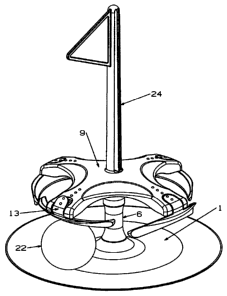
Figure 1 is a side view showing the general assembly of the invention.
2o Figure 2 is a plan view of the ball trap shown in figure 1.
Figure 3 is a section view of the general assembly shown in figure 1.
Figure 4 is a part section view of the hinge of the ball trap shown in figure
1.
Figure 5 is a view of a ball acting on the side of the flap.
Figure 6 is a perspective view of the device as it would be set up on a
suitable surface.
3o Figure 7 is a plan view of a preferred embodiment of the invention showing
a ball acting
on a flap.
Figure 8 is a perspective view of the preferred embodiment shown in Figure 7.
CA 02572543 2006-12-29
WO 2006/003364 PCT/GB2005/002281
Figure 9 is a side view of the preferred embodiment shown in Figure 8.
By way of example, and with initial reference to Figures 1 to 6 the device
consists of a
thin flat base 1 larger than the diameter of the circular hole the device is
to simulate. The
5 edge of the base 1 may have a chamfer or radius 2. The simulated hole is
marlced 4 on the
upper side of the base 1 and may additionally be augmented by a slight
depression or a
series of holes at the same diaineter. A vertical post 6 rises from the centre
of the
simulated hole 4 and is attached to the base 1 tlirough a hole 3. Post 6 is
held in place by
a bayonet feature or separate nut 23 on the underside of base 1. Alternatively
post 6 may
lo be an integral part of base 1.
The top of post 6 has a vertical spigot 7 and flange 8 on to which is mounted
carrier 9.
Spigot 7 may be tapered with a matching taper on carrier 9. Carrier 9 has a
plurity of
arms 10 radiating outwards. At the ends of each arin 10 is a hinge 11 and flap
12 largely
suspended from the hinge 11. A tab 13 extending inwards from the top of the
flap 12
contacts the top of the arm 10 preventing the lower part 14 of the flap 12
from rotating
outwards but allowing full rotation inwards until the flap 12 contacts the
lower profile 15
of the arm 10.
The lower part 14 of the flap 12 extends sideways fiom the hinge 11 in both
directions in
a circular path concentric and fiu-ther out to the simulated hole outline 4.
The sides 16 of
the flap 12 stop at a point that allows clearance 17 to the adjacent flap in
all articulations
of both flaps. The lower edge 18 of the flap 12 may be straight but is
preferably curved
down at the ends when flap 12 is in its rest position. Furthermore it is
preferred the lower
edge 18 is approximate to the simulated hole outline when flap 12 is in its
operating
position. Towards the sides 16 there is a chamfer or radius 19. Optionally at
the sides of
the flap 12 there is a tab 20 extending inwards. The upper edges 21 of the
flap may be
any profile but must provide sufficient clearance to the lower profile 15 of
the arm 10
when the flap 12 is fully articulated inwards.
A preferred embodiment of the invention is illustrated in Figures 7 to 9.
Comparing, in
particular, Figures 2 and 7; and Figures 6 and 8 the differences evident in
this, the
preferred embodiment, the base 1 is illustrated without the optional chamfer 2
about its
CA 02572543 2006-12-29
WO 2006/003364 PCT/GB2005/002281
6
outer edge; and the flaps 12 whilst extending eitlier side of the hinge 11 in
a generally
curved inaruzer being concentric to the simulated hole 4 the flap sides 16 do
not include a
tab 20 extending inwards. All other coinmon features are present.
The mode of worlcing is illustrated in Figures 1 to 9 and described in the
following
examples. The device is placed on a suitable surface. A ball 22 rolls on said
surface in a
straight path approximately towards the centre of the device. The bal122 rolls
on to base
I which is sufficiently thin to mininlise any disturbance to the direction or
speed of the
ball. Upon contacting flap 12 the ball causes it to rotate inwards until the
ball 22 can pass
1o underneath flap 12. Once the ball 22 is inside the device and no longer in
contact with the
flap 12 tlie flap 12 retunis to its rest position thereby trapping ball 22.
In anotlier example ball 22 approaches tangentially to the simulated hole 4 or
at an angle
other than directly towards the centre of the device. Upon contacting flap 12
ball 22
causes flap 12 to rotate inwards. If a ball 22 contacts flap side 16 then the
chanfer or
radius 19 and or tab 20 (if present) will slide up the surface of ball 22
causing flap 12 to
rotate inwards.
In all embodiments if the centre of ball 22 crosses lower edge 18 of flap 12
tlien ball 22
will continue or be deflected inwards to be captivated by the device. If
ba1122 does not
cross lower edge 18 then ball 22 will continue on its present patli and flap
12 will return
to its rest position without trapping ball 22. In all exainples, once inside
tlie device, ball
22 is prevented from leaving the device as the flaps 12 are prevented from
rotating
outwards by tab 13. In situations where the ball 22 is travelling at such a
speed tliat it
would not fall into a normal hole this may be simulated by carrier 9 in a
number of ways.
For example the carrier 9 may tip or lift vertically off the top of post 6 to
allow the ball 22
to escape from the device in a similar maimer to normal ball behaviour. To aid
carrier 9
to tip or lift it may be mounted on a conical or rounded spigot 7.
Alternatively, tlus escape
can be facilitated by the carrier 9 being formed from a resiliently
deforrnable preferably
plastics material which in such a situation will sufficiently distort or flex
upon iinpact to
allow the ball to escape.
A feature of the device so described is the compact aiid portable size wlien
the flap aa.1d
CA 02572543 2006-12-29
WO 2006/003364 PCT/GB2005/002281
7
A feature of the device so described is the compact and portable size when the
flap and
carrier assembly is dis-assembled from the post and the post is dis-assembled
from the
base, allowing all the components to be packaged in a small flat box.
An enhanceinent to the device is flagpole 24 which fits into a hole 25 in top
of post 6.
Another enhancement is spike 26 which fits into hole 27 in the bottom of post
6. This
spilce 26 then protrudes from the bottom of the device to give it additional
stability on soft
ground.
In a further embodiment carrier 9 is suspended from the bottom of a post or
arched rod
which is attached to a fixed or portable structure. This allows the removal of
post 6
thereby further enhancing the siinulation of a hole.
Since the flap 12 is mounted to be freely moveable and is designed to have low
inertia, it
causes negligible deflection to the ball's direction or speed. At its
operating point the
profile of the flap's lower edge 18 approximates the hole but acts upon the
top ratlier than
the bottom of the ball. Hence the device accurately simulates a real golf hole
without the
need for an actual hole. The base has also been selected to be particularly
thin so that it
2o does not substantially deflect the trajectory of the ball.
In order to accurately siinulate a golf ball being sent into a hole, the
carrier and/or carrier
and post assemblies are inherently flexible structures sufficient so that when
the ball
enters beneath the carrier and impacts the flaps located at the opposite side
from the entry
of the ball, the carrier and/or carrier and post assemblies can deflect
elastically to allow
the exit of the ball if the ball is above a pre-determined velocity
corresponding to the
velocity by wliich a golf ball travelling into a hole would instead of sinking
into the hole
exit the hole even though its trajectory passes over the hole.