Note: Descriptions are shown in the official language in which they were submitted.
CA 02572672 2006-12-29
0002674USU
METHOD FOR AUTOMATICALLY ADJUSTING THE DEFROST INTERVAL IN A HEAT PUMP SYSTEM
CROSS-REFERENCE TO A RELATED APPLICATION
The present application claims priority in U.S. Provisional Patent
Application No. 60/760,540, filed January 20, 2006, which is incorporated in
its entirety by reference herein.
BACKGROUND OF THE INVENTION
1. Field of the Invention
[0001] The present invention relates generally to a method for automatically
adjusting the interval of time between defrost cycles in a heat pump system.
The method utilizes measurements of the duration of the previous defrost
cycle or cycles, and adjusts the time interval before initiating the next
defrost
cycle so that any frost build-up can be defrosted without unnecessary defrost
cycles.
2. Description of the Related Art
[0002] Heat pump systems generally build frost on the outdoor heat
exchanger coil when operating in the heating mode. This frost build-up can
CA 02572672 2006-12-29
0002674USU
gradually degrade the heat exchanger and system performance in the form of
heating capacity and efficiency. If the frost is not cleared, it can continue
to
build-up until the heat exchanger coil becomes completely blocked with ice.
At this point, in most heat pump systems, protective devices typically cause
the system to shut down. If the protective devices are not effective,
equipment failure could occur.
[0003] For these reasons, it is common practice in most heat pump systems
to incorporate a way to defrost. For example, most heat pump systems
operate in the cooling (air conditioning) mode for short periods of time,
thereby reversing the flow of refrigerant in the system with the help of a
reversing valve. Also, during this defrost cycle, the outdoor fan, which blows
air over the outdoor heat exchanger coil, is stopped. When the heat pump
operates in the cooling mode without the outdoor fan running, the outdoor
heat exchanger coil heats up quickly, to melt the frost.
[0004] Defrosting in this manner has its penalties. Running the heat pump
in cooling mode while the home needs heating capacity clearly leads to
wasted energy. Furthermore, the cold air delivered inside the home can be
quite uncomfortable in the heating season. To warm up the air to comfortable
levels during a defrost cycle, most heat pump systems activate a
supplemental heat source. Typically, this supplemental source is electric
strip
heat, which itself consumes a great amount of electric energy. Another
problem is that two refrigerant flow reversals are needed in a defrost cycle,
2
CA 02572672 2006-12-29
0002674USU
from heating to cooling and back to heating. The flow reversals are usually
quite noisy, and are an annoyance to the consumer.
[0005] In order to minimize the negative impact of these defrost cycles on
energy usage, noise levels, and consumer comfort, it is desirable to reduce
the frequency and duration of defrost cycles. The ideal system should defrost
just often enough to eliminate frost and no more. This can be quite
challenging because the rate of frost build up varies with the weather.
Outdoor temperatures, humidity and wind levels all play a role in determining
how much frost accumulates on the coils. Different climatic areas have
different weather patterns and, therefore, different defrost requirements.
[0006] Several defrost control strategies and algorithms have been
employed in the prior art. Most defrost controls involve use of electronic
circuits or microprocessors. The general approach is to estimate the
presence of sufficient frost to initiate a defrost cycle, and then determine a
sufficient clearing of frost from the coils to terminate the defrost cycle.
[0007] The most common method of terminating defrost cycles involves
sensing the temperature at an appropriate point in the heat exchanger coil.
During a defrost cycle, the coil starts to heat up as the hot compressed
refrigerant flows through it. However, the heat is first used to melt whatever
amount of frost there is on the coil. Once all the frost is cleared, the heat
starts to increase the temperature of the coil very quickly. A defrost control
3
CA 02572672 2006-12-29
0002674USU
that has a coil temperature sensor can detect this increased temperature and
terminate the defrost cycle. Alternately, a pressure sensor or pressure switch
can be used. Some simple defrost controls have no sensors, and instead run
all defrost cycles for a fixed duration.
[0008] Determining when to initiate a defrost cycle is more challenging. A
number of methods are employed in the prior art. These methods generally
fall into two categories: "demand" defrosts and "timed" defrosts. Demand
defrosts attempt to estimate the actual frost level or rate of frost
accumulation
under any set of conditions and wait until this estimate indicates a "demand"
for defrosting before initiating. Since there is no practical direct sensing
of
frost level, these demand defrost methods use surrogate sensors to provide
an estimate of the frost level. One example is to use the difference between
coil temperature and outdoor air temperature. In this method, when the coil
temperature falls sufficiently below the outdoor air temperature, a defrost
cycle is initiated. The applicable principle is that a relatively colder coil
will
accumulate more frost. Many other schemes with varying degrees of
sophistication have been used. These methods are not completely foolproof.
They may defrost too frequently or too infrequently. The consequences are
either a "block of ice" on the coils or complaints by consumers about too many
defrosts.
[0009] The alternative, a timed defrost method, is much simpler. The
control simply has a fixed time interval between defrost cycles. Typically,
this
4
CA 02572672 2006-12-29
0002674USU
time interval is in terms of accumulated heating mode operating time, not just
elapsed time. Also, the installer of the heat pump system can typically select
this fixed time interval from several available choices such as: 30 minutes,
60
minutes, 90 minutes, and 120 minutes. Once selected, the fixed time interval
is applied for the life of the product, unless changed again by a service
technician. Typically the defrost interval is selected by installing
technicians
to suit, in their judgment, the climatic conditions in their area.
[0010] As mentioned above, these conditions can change dynamically with
the weather. A fixed "timed" defrost interval cannot always match the current
defrost needs. This can lead to the same problems as "demand" defrosts.
[0011] While both methods described above have been extensively used,
there is a desire for improvement.
SUMMARY OF THE INVENTION
[0012] The present disclosure provides a method of defrost control that is
simple and robust, and that dynamically adjusts to changing conditions to
ensure problem-free operation of a heat pump system. The primary focus is
to eliminate the formation of excessive amounts of frost, while still reducing
the frequency of defrost cycles when operating under less severe conditions.
CA 02572672 2006-12-29
0002674USU
[0013] The present disclosure also provides that the timed defrost interval
dynamically changes in response to changing frost conditions, rather than
being fixed.
BRIEF DESCRIPTION OF THE DRAWINGS
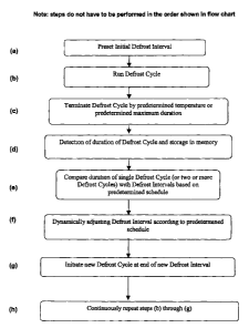
[0014] Figure 1 is a flow chart of the method of the present invention.
DETAILED DESCRIPTION OF THE INVENTION
[0015] The present disclosure provides a method to dynamically and
automatically adjust the interval of time between defrost cycles in a heat
pump
system. The method involves tracking the time duration of the previous
defrost cycle (or cycles) and then dynamically adjusting the length of time
before the next defrost cycle is initiated.
[0016] During a defrost cycle, also called a defrost routine, the heat that
flows into the heat exchanger coil is first consumed in melting the frost, if
any,
that has previously built up on the coil. Once the frost is cleared, the heat
quickly increases the temperature of the coil. The defrost control, upon
sensing this increased coil temperature, terminates the defrost cycle. The
time duration of a defrost cycle, therefore, primarily depends on the amount
of
previously accumulated frost on the coil. Greater amounts of accumulated
frost result in longer defrost cycles. For example, in typical residential
heat
6
CA 02572672 2006-12-29
0002674USU
pump systems, defrost cycles range between one minute and ten minutes in
duration.
[0017] A key feature of the present disclosure is that the duration of the
defrost cycle is a very good measure of the frosting conditions present at
that
time. A long defrost cycle indicates weather conditions that cause heavy frost
accumulation. In such a situation, defrost cycles should occur more
frequently to keep up with frost accumulation. On the other hand, a short
defrost cycle indicates weather conditions that are not causing significant
frost
accumulation. This situation requires less frequent defrost cycles. The
defrost cycle duration is a very simple but direct measure of frosting
conditions, unlike previous demand defrost methods that rely on temperatures
or pressures.
[0018] The present disclosure provides a method by which shorter defrost
cycles are followed by longer time intervals until the next defrost cycle
begins,
and, conversely, a method by which longer defrost cycles is followed by
shorter time intervals before the next defrost cycle begins.
[0019] In an embodiment of the present disclosure, initiation of a defrost
cycle in a heat pump starts a flow of heat into the heat exchanger. Any frost
that has previously accumulated on the coils, is melted by the heat. Once the
frost is cleared, the heat quickly increases the temperature of the coil,
until
there is termination of the defrost cycle when either:
7
CA 02572672 2006-12-29
0002674USU
{
(a) the coil temperature exceeds 65 degrees Fahrenheit ( F); or
(b) the defrost cycle lasts for 10 minutes, which is the upper time limit.
The defrost control in this embodiment includes a microprocessor that is
capable of keeping track of multiple time intervals. The microprocessor tracks
the time duration of every defrost cycle, which is the time between the
initiation of a defrost cycle and its termination. Based upon the duration of
time of the most recent defrost cycle, the microprocessor initiates the next
defrost cycle according to the following schedule:
Duration of Defrost Cycle Defrost Interval
Less than 3 minutes 120 minutes
3 to 5 minutes 90 minutes
to 7 minutes 60 minutes
7 to 10 minutes 30 minutes
As used in the schedules for this disclosure, Duration of Defrost Cycle means
the length of time (duration) of the last defrost cycle from its initiation to
termination. Defrost Interval means the amount (interval) of time between the
end of the previous defrost cycle and the beginning of a new defrost cycle.
The first time the system operates, that is before any defrost cycle has
occurred, the defrost interval is usually set for 30 minutes, although this
single
8
CA 02572672 2006-12-29
0002674USU
{
time period can be selected by the manufacturer, installer, or operator of the
heat pump system.
[0020] For example, using the schedule provided for in this embodiment of
the present disclosure, if a given defrost cycle operated for a total duration
of
4 minutes until it reached the termination temperature of 65 F, the
microprocessor would schedule the next defrost cycle to initiate approximately
90 minutes after the end of the most recent defrost cycle. If the next defrost
cycle required only 2 minutes to clear any accumulated frost and to heat the
coils to the termination temperature of 65 F, the microprocessor would
schedule the next defrost cycle to initiate approximately 120 minutes after
the
end of the latest defrost cycle. This dynamic relationship of regulating the
interval between defrost cycles continues for the service life of the heat
pump
system. It should forestall the build-up of ice on the heat pump coils while
minimizing the annoyance and energy use caused by defrost cycles that are
too frequent.
[0021) The termination temperature used to signal the end of the defrost
cycle in this embodiment of the present disclosure is 65 F, which is well
above the freezing temperature (32 F) of the ice that forms on the coils.
However, a range of termination temperatures from about 45 F to about 75 F
are acceptable. The termination temperature can be pre-set by the
manufacturer or set by the heat pump system operator, depending on the
design parameters of a particular heat pump system. Also, termination
9
CA 02572672 2006-12-29
0002674USU
temperature can be changed in response to geographical and seasonal
variations.
[0022] In a preferred embodiment of the present disclosure, the maximum
time limit for a defrost cycle is 10 minutes. The 10 minute maximum time limit
for the duration of the defrost cycle is based on experience with typical heat
pump systems. However, this maximum time limit can be changed or even
eliminated depending on the design parameters of a particular heat pump
system. For instance, a design parameter that would influence the maximum
defrost time could be placement of the heat pump unit inside of a climate-
controlled residence, instead of outside of the residence in an unheated
storage room.
[0023] Although the above embodiment of the present disclosure provides
four distinct defrost intervals (30, 60, 90, or 120 minutes), additional
intervals
values could be added, either within the 30 - 120 minute range or outside of
this range.
[0024] Another embodiment of the present disclosure that uses a different
group of defrost intervals for the heat pump system could also be set to the
following schedule:
Duration of Defrost Cycle Defrost Interval
Less than 1 minute 140 minutes
CA 02572672 2006-12-29
0002674USU
2 to 3 minutes 110 minutes
3 to 4 minutes 95 minutes
4 to 5 minutes 80 minutes
to 6 minutes 70 minutes
6 to 7 minutes 45 minutes
7 to 8 minutes 35 minutes
8 to 9 minutes 30 minutes
9 to 10 minutes 25 minutes
to 11 minutes (maximum defrost cycle time) 20 minutes
100251 As illustrated by the embodiments of the present disclosure, the
relationship between the Duration of Defrost Cycle and the Defrost Interval
can be any mathematical relationship that follows the basic principle that the
time of the Defrost Interval increases as the time of the Duration of Defrost
Cycle decreases. That is, the mathematical relationship between the Duration
of Defrost Cycle and Defrost Interval can be either a linear or non-linear
function, as long as an inverse relationship between these two time periods is
maintained.
[0026] The lower limit for a Defrost Interval can be less than 30 minutes, as
illustrated above. Of course, the heat pump system cannot defrost
continually, or the heat pump could not accomplish its purpose of maintaining
a comfortable temperature in the living space. The likely lower limit of time
between defrost cycles is probably about-15- minutes, which would only be
11
CA 02572672 2006-12-29
0002674USU
necessary in those conditions most conducive to frost formation, namely
extreme cold and high air moisture content.
[0027] The present disclosure provides no upper time limit on the interval
between defrost cycles. Warm temperatures and low moisture content (dry)
outdoor air are not conducive to frost formation, and the interval between
defrost cycles can probably be programmed to extend beyond 140 minutes in
certain climates and seasons without substantially increasing the risk of
frost
accumulation on the heat pump coils.
[0028] A preferred embodiment of the present disclosure schedules the
Defrost Interval based on a single data point; i.e., the most recent Defrost
Duration. Scheduling the Defrost Interval based only on the most recent data
point has the advantage of being most responsive to current conditions, such
as weather, temperature, humidity, as well as the condition of the heat pump
system, such as frost accumulation on the coils.
[0029] However, the present disclosure contemplates an embodiment
where the microprocessor or other control device determines a schedule of
Defrost Intervals where each interval is based on two or more previous
Defrost Duration times, which are then averaged, or otherwise trended. This
embodiment is somewhat less responsive to current conditions than the
preferred embodiment described above, but offers the advantage of more
predictable Defrost Intervals. Microprocessors for heat pump systems are
12
CA 02572672 2006-12-29
0002674USU
capable of averaging and trending data for this embodiment if programmed to
do so.
[0030] A control device as used in the present invention is a timer that
monitors the Defrost Duration, and establishes the Defrost Interval, and
automatically initiates the next defrost cycle based on a schedule such as
those described above. The control device may be electrical or mechanical,
or a combination of the two. The preferred embodiment uses a
microprocessor as the control device that monitors the Defrost Duration,
establishes the Defrost Interval, and then automatically initiates the next
defrost cycle based on a schedule such as those described above. Another
embodiment of the present disclosure could use a digital circuit timer with
logical elements instead of, or in addition to, a microprocessor.
[0031] An embodiment of the present disclosure provides a method to
dynamically adjust a defrost interval in a heat pump system based on a
duration of a prior defrost routine by detecting the duration of a prior
defrost
routine, comparing the duration of a prior defrost routine with a schedule of
defrost routines and defrost intervals, and dynamically adjusting the defrost
interval based on a schedule of defrost routines and defrost intervals,
wherein
the numerical values for the duration of the defrost routines and the defrost
intervals are inversely related. The inverse function relating the duration of
the defrost routines and the defrost intervals may be a linear or a non-linear
function.
13
CA 02572672 2006-12-29
0002674USU
[0032] The method may further comprise a step in which the method is
repeated on a continuous basis unless deactivated by the heat systems
operator or user/consumer.
[0033] The method may use an electronic processor to compare the
duration of the prior defrost routine with the schedule of defrost routines
and
defrost intervals.
[00341 The initial defrost interval of this method may be preset. The
duration at which the initial defrost interval is preset may be determined by
the
manufacturer, the heat system installer or operator, or by the consumer/user.
[0035] The defrost routine used in an embodiment of the method may be
set to terminate operation when the condenser coils reach a temperature of
about 45 F to about 75 F, and preferably a temperature of about 65 F. The
temperature at which the defrost routine is terminated is preset by the
manufacturer and can be changed by the heat pump system operator in
response to geographical and seasonal variations.
[0036] The embodiment provides a method for dynamically adjusting the
defrost interval based only on the duration of the most recent prior defrost
routine, or by averaging the duration of two or more prior defrost routines.
The
dynamic quality of the method is most sensitive to changes in temperature
14
CA 02572672 2006-12-29
0002674USU
and frost when the method uses only the duration of the most recent prior
defrost routine.
[0037] Another embodiment of the present disclosure provides a heat pump
system comprising condenser coils and a control device. The control device
is a timer that monitors the duration of a defrost routine, establishes the
defrost interval, and automatically initiates the next defrost cycle. The
control
device is electrical (such as a microprocessor or digital circuit timer with
logical elements), or mechanical, or a combination thereof.
[0038] While the present disclosure has been described with one or more
exemplary embodiments, it will be understood by those skilled in the art that
various changes may be made and equivalents may be substituted for
elements thereof without departing from the scope thereof. In addition, many
modifications may be made to adapt a particular situation or material to the
teachings of the disclosure without departing from the scope thereof.
Therefore, it is intended that the disclosure not be limited to the particular
embodiment(s) disclosed as the best mode contemplated for carrying out this
invention, but that the invention will include all embodiments falling within
the
scope of the appended claims.