Note: Descriptions are shown in the official language in which they were submitted.
CA 02572787 2007-01-02
WO 2006/003648 PCT/IL2005/000694
BATTERY-ASSISTED BACKSCATTER RFID TRANSPONDER
FIELD OF THE INVENTION
The present invention relates generally to radio frequency identification
(RFID)
systems, and particularly to battery-assisted backscatter RFID transponders,
their components
and methods for producing RFID transponders.
BACKGROUND OF THE INVENTION
Radio frequency identification (RFID) systems are used in a variety of
applications,
ranging from warehouse inventory control and container tracking, through
automatic toll
payment, to automatic supermarket cashier applications. In a typical RFID
system, an RF
transponder is attached to, or incorporated into, a tracked object. RF
transmissions between an
interrogation device or a reader and the transponder are used for identifying
or controlling the
object, reading data, writing data or otherwise communicating with the
transponder.
SUMMARY OF THE INVENTION
RF transponders are commonly classified in terms of the use they make of an
internal
power source. A passive transponder has no internal power source and uses the
energy of the
RF radiation transmitted by the reader (referred to herein as interrogation
radiation) for
powering the transponder circuitry and for transmitting response radiation
back to the reader.
(The response radiation typically comprises information, such as an
identification number,
transmitted from the transponder to the reader.) An active transponder
comprises an internal
power source that is used for both powering the transponder and for generating
the RF energy
required for transmitting the response radiation. A battery-assisted
transponder (also referred to
as a semi-active or a semi-passive transponder) comprises an internal power
source. The energy
of the response radiation is derived from the interrogation radiation provided
by the reader, and
the transponder circuitry is powered by the internal power source. Some
battery-assisted
transponders, referred to as backscatter transponders, generate the response
radiation by
backscattering the interrogation radiation from the transponder antenna.
Backscatter
transponders typically transmit information to the reader by modulating the
backscattered
radiation.
Battery-assisted backscatter transponders, as described in the background art,
can use
part of the energy of the received interrogation radiation for powering the
transponder circuitry,
in parallel to their internal battery. This configuration reduces the amount
of energy that is
available for backscattering, thus reducing the achievable communication range
of the
transponder:
1
CA 02572787 2007-01-02
WO 2006/003648 PCT/IL2005/000694
Embodiments of the present invention provide improved battery-assisted
backscatter RF
transponder configurations that maximize the achievable communication range
and extend the
lifetime of the internal power source. Exemplary performance measurements of
such
transponders in various challeriging test environments are shown hereinbelow.
In some embodiments, an integrated circuit (IC) in the transponder modulates
the
information to be transmitted to the reader onto the backscattered radiation
using backscatter
modulation. The IC modulates a radar cross-section (RCS) of the transponder
antenna by
varying the impedance at the feed-point of the antenna. In particular, when an
extreme
mismatch, such as an open circuit, is introduced at the antenna feed-point,
the energy of the
interrogation radiation available for backscattering is maximized, thus
maximizing the
communication range of the transponder.
In some embodiments, the antenna and the IC are jointly optimized so as to
maximize
the impedance mismatch at the antenna feed-point, and hence maximize the
achievable
communication range. Additionally or alternatively, a modulation depth
(denoted ARCS)
defined as the ratio between the different RCS values is also maximized.
The RF transponders described herein can operate under various protocols, such
as, but
not limited to various transponder-talks-first (TTF) and reader-talks-first
(RTF) protocols. Such
protocols typically defme the different modes of operation for the
transponder. In some
embodiments, an energy saving (battery saving) module in the IC activates and
deactivates
parts of the transponder responsively to the operational modes defmed in the
protocol, in order
to reduce the energy consumption from the internal power source. In some
embodiments, the
energy saving module controls the operational modes of the transponder
responsively to
predetermined timeout conditions, to further reduce energy consumption.
Embodiments of the present invention also provide improved methods for
producing
RF transponders. In some embodiments, the power source of the transponder is a
thin and
flexible battery that is printed on the same substrate as the IC and the
antenna, as part of the
transponder production process.
There is therefore provided, in accordance with an embodiment of the present
invention, a radio frequency (RF) transponder, including:
at least one battery, which is coupled to provide electrical power for
operating the
transponder;
at least one antenna, which is configured to receive and backscatter RF
interrogation
radiation from an interrogation device; and
an integrated circuit (IC), which is arranged to store a code including
information and,
powered only with energy provided by the battery, to vary a radiation
characteristic of the
2
CA 02572787 2007-01-02
WO 2006/003648 PCT/IL2005/000694
antenna responsively to the code so as to modulate the information onto the
backscattered
radiation.
In some embodiments, the transponder includes a substrate having at least one
of the IC,
the at least one antenna and the at least one battery disposed thereon.
In a disclosed embodiment, the at least one battery includes at least a
printed anode
layer, a printed electrolyte layer and a printed cathode layer disposed in at
least one of a co-
planar and a co-facial configuration. The electrolyte layer is disposed
between the anode layer
and the cathode layer. In another embodiment, the substrate is flexible.
In yet another embodiment, the transponder has a thickness no greater than 1
mm and a
bending radius no greater than 25 mm.
In an embodiment, the transponder is attached to an object and at least part
of the
information in the IC is related to the object. Additionally or alternatively,
the transponder is
adapted to be attached around a corner of an object so that the at least one
battery is oriented in
a first plane and the at least one antenna is oriented in a second plane
different from the first
plane.
In another embodiment, the at least one antenna is selected from the group
consisting of
at least one of a monopole, a bent monopole, a dipole, a bent dipole, a patch,
an array antenna
and a combination thereof. Additionally or alternatively, the at least one
antenna is configured
to receive and backscatter the interrogation radiation in one of an ultra-high
frequency (UHF)
range and a microwave frequency range. Further additionally or alternatively,
the at least one
antenna is arranged to receive and backscatter transverse electromagnetic
(TEM) radiation.
In yet another embodiment, the at least one antenna includes a feed-point, the
radiation
characteristic includes a radar cross-section (RCS) of the at least one
antenna, and the IC is
arranged to vary a load impedance at the feed-point of the at least one
antenna so as to vary the
RCS of the at least one antenna between two or more different RCS values. In
still another
embodiment, the IC includes a solid-state switch operatively coupled to the
feed-point of the at
least one antenna, which is arranged to switch the load impedance between a
first impedance
and a second impedance, responsively to a binary representation of the code.
In an embodiment, the IC is arranged to introduce a low resistive load
condition at the
feed-point of the at least one antenna so as to maximize at least one of the
two or more RCS
values, thereby maximizing a communication range of the transponder.
Additionally or
alternatively, the IC is arranged to maximize a modulation depth defmed as a
ratio between two
of the two or more RCS values. Further additionally or alternatively, the at
least one antenna
and the IC are arranged to jointly maximize the modulation deptll and a
communication range
of the transponder.
3
CA 02572787 2007-01-02
WO 2006/003648 PCT/IL2005/000694
In an embodiment, the interrogation radiation received by the at least one
antenna has a
first power level, and the at least one antenna and the IC are arranged to
backscatter the
interrogation radiation at a second power level that is greater than 75% of
the first power level.
In another embodiment, the second power level is greater than 95% of the first
power level.
In still another embodiment, the IC is configured to comply with an operation
protocol
defining two or more operational modes. Additionally or alternatively, the IC
includes an
energy saving module, which is arranged to.activate and deactivate parts of
the transponder
responsively to the operational modes so as to reduce an energy consumption
from the at least
one battery. In yet another embodiment, the protocol includes at least one of
a transponder-
talks-first (TTF) and a reader-talks-first (RTF) protocol.
In an embodiment, the protocol includes the RTF protocol, and the IC is
configured to
analyze signals carried by the interrogation radiation, to progressively
activate components of
the transponder responsively to the analyzed signals so as to reduce an energy
consumption
from the at least one battery, to assess a relevance of the interrogation
radiation to the
transponder based on the analyzed signals, and to enable the transponder to
react to the
interrogation radiation based on the relevance. Additionally or alternatively,
the IC is arranged
to evaluate one or more timeout conditions and to deactivate predetermined
components of the
transponder responsively to the timeout conditions after having detected a
presence of the
interrogation radiation.
In another embodiment, the IC includes a battery status indicator, which is
configured to
indicate an availability of sufficient electrical power from the at least one
battery, and the IC is
configured to draw electrical power from the interrogation radiation
responsively to a reported
unavailability of sufficient battery power as determined by the battery status
indicator.
In yet another embodiment, the transponder includes at least one sensor, and
the IC is
arranged to receive an indication of a local condition in a vicinity of the
transponder from the at
least one sensor.
In still another embodiment, the transponder includes an energy conversion
circuit,
which is arranged to draw excess power from the interrogation radiation, when
the excess
power is available, and to perform at least one of powering the IC and
charging the at least one
battery using the drawn excess power.
In an embodiment, the IC is arranged to decode and react to interrogation data
carried
by the interrogation radiation, the interrogation data including at least one
of a command
relating to an operation of the transponder and input data to be written to
the transponder.
There is also provided, in accordance witll an embodiment of the present
invention, a
radio frequency (RF) transponder, including:
4
CA 02572787 2007-01-02
WO 2006/003648 PCT/IL2005/000694
a battery, which is coupled to provide electrical power for operating the
transponder;
an antenna, which is arranged to receive and backscatter RF interrogation
radiation
from an interrogation device;
an integrated circuit (IC), which is arranged to store a code including
information and,
powered with energy provided by the battery, to vary a radiation
characteristic of the antenna
responsively to the code so as to modulate the information onto the
backscattered interrogation
radiation; and
a substrate, on which the battery, IC and antenna are disposed, and which is
adapted to
be fixed around a corner of an object so that the battery is oriented in a
first plane and the
antenna is oriented in a second plane different from the first plane.
There is further provided, in accordance with an embodiment of the present
invention, a
radio frequency (RF) transponder, including:
an antenna, which is arranged to receive interrogation radiation at a first
power level
from an interrogation device and to backscatter the interrogation radiation at
a second power
level that is greater than 75% of the first power level; and
an integrated circuit (IC), which is arranged to store a code including
information and to
vary a radiation characteristic of the antenna responsively to the code so as
to modulate the
information onto the backscattered radiation.
In an embodiment, the second power level is greater than 95% of the first
power level.
There is additionally provided, in accordance with an embodiment of the
present
invention, a radio frequency (RF) transponder, including:
an antenna, which is arranged to receive first RF radiation carrying signals
from an
interrogation device and to transmit second RF radiation responsively to the
first RF radiation;
a battery, which is coupled to provide electrical power for operating the
transponder;
and
an integrated circuit (IC), which is operative in accordance with a reader-
talks-first
(RTF) protocol, and which is configured to detect a presence of the first RF
radiation, to
analyze the signals carried by the first RF radiation, to progressively
activate components of the
transponder responsively to the analyzed signals so as to reduce an energy
consumption from
the battery, to assess a relevance of the first RF radiation to the
transponder based on the
analyzed signals, and to enable the transponder to transmit the second RF
radiation based on
the relevance.
In an embodiment, the IC is configured to assess the relevance of the first RF
radiation
by performing at least one of detecting a pattern in the first RF radiation
and determining
addressing infoimation in the first RF radiation. In another embodiment, the
IC is arranged,
5
CA 02572787 2007-01-02
WO 2006/003648 PCT/IL2005/000694
responsively to the relevance of the first RF radiation, to perform at least
one of rejecting RF
radiation not generated by an RF reader and rejecting RF radiation not
addressed to the
transponder.
There is also provided, in accordance with an embodiment of the present
invention, a
method for transmitting information from a radio frequency (RF) transponder,
including:
providing a battery for operating the transponder;
configuring an antenna to backscatter RF interrogation radiation that is
transmitted from
an interrogation device; and
varying a radiation characteristic of the antenna responsively to the
information so as to
modulate the information onto the backscattered radiation. The energy used to
vary the
radiation characteristic is not derived from the interrogation radiation.
In an embodiment, providing the battery includes applying a printed battery to
a
substrate having at least one of the IC and the antenna disposed thereon. In
another
embodiment, the battery is no greater than 1 mm thick.
In yet another embodiment, the battery includes a flexible thin-layer open
liquid-state
electrochemical cell including a first layer of insoluble negative electrode,
a second layer of
insoluble positive electrode and a third layer of aqueous electrolyte, the
third layer being
disposed between the first and second layers and including:
(a) a deliquescent material for keeping the open cell wet at all times;
(b) an electroactive soluble material for obtaining required ionic
conductivity; and
(c) a water-soluble polymer for obtaining a required viscosity for adhering
the first and
second layers to the third layer.
There is additionally provided, in accordance with an embodiment of the
present
invention, a method for manufacturing a radio frequency (RF) transponder,
including: .:
providing a battery for operating the transponder;
configuring an antenna to backscatter RF interrogation radiation that is
transmitted from
an interrogation device;
disposing the antenna and the battery on a substrate, wherein the substrate is
configured
to allow for application of the transponder around a corner of an object, so
that the battery is
oriented in a first plane and the antenna is oriented in a second plane
different from the first
plane.
There is further provided, in accordance with an embodiment of the present
invention, a
method for transmitting information from a radio frequency (RF) transponder,
including:
6
CA 02572787 2007-01-02
WO 2006/003648 PCT/IL2005/000694
configuring an antenna to receive an interrogation radiation at a first power
level from
an interrogation device and to backscatter the interrogation radiation at a
second power level
that is greater than 75% of the first power level;
storing a code including the information; and
varying a radiation characteristic of the antenna responsively to the code so
as to
modulate the information onto the backscattered radiation.
In an embodiment, the second power level is greater than 95% of the first
power level.
There is additionally provided, in accordance with an embodiment of the
present
invention, a method for manufacturing a radio frequency (RF) transponder,
including:
providing a substrate;
applying on the substrate an antenna suitable for backscattering radio-
frequency (RF)
radiation;
applying an integrated circuit (IC) to the substrate, and coupling the IC to
vary a
radiation characteristic of the antenna so as to modulate information onto the
backscattered
radiation; and
printing a battery on the surface of the substrate, so as to provide
electrical power for
powering the transponder.
In an embodiment, printing the battery includes printing one or more battery
layers in at
least one of a co-facial configuration and a co-planar configuration using
respective inks
including battery layer materials. In another embodiment, the layer material
includes at least
one of zinc, manganese dioxide (Mn02) and zinc chloride (ZnC12).
In yet another embodiment, printing the battery includes:
forming a first battery assembly including:
printing a first electrode layer on the surface of the substrate;
applying an electrolyte on the first electrode layer; and
applying a separator layer on the electrolyte of the first electrode layer;
forming a second battery assembly including:
printing a second electrode layer of opposite polarity to the first electrode
layer
on a second substrate; and
applying the electrolyte on the second electrode layer; and
joining together the first battery assembly and second battery assembly so
that the layers
are stacked and the electrolyte of the second electrode layer is in co-facial
contact with the
separator layer.
7
CA 02572787 2007-01-02
WO 2006/003648 PCT/IL2005/000694
In still another embodiment, applying the antenna includes printing the
antenna on the
substrate. In another embodiment, the IC includes an organic polymer IC and
applying the IC
includes using a printing technique to apply the IC. Additionally or
alternatively, applying the
antenna and the IC and printing the battery include printing a fully printable
transponder.
There is also provided, in accordance with an embodiment of the present
invention, a
method for reducing energy consumption from a battery in a radio-frequency
(RF) transponder
operating in accordance with a reader-talks-first (RTF) protocol, including:
detecting a presence of RF radiation at the transponder;
analyzing signals carried by the detected RF radiation;
progressively activating components of the transponder responsively to the
analyzed
signals, so as to reduce the energy consumption;
assessing a relevance of the RF radiation to the transponder based on the
analyzed
signals; and
based on the relevance, enabling the transponder to react to the RF radiation.
There is further provided, in accordance with an embodiment of the present
invention, a
radio-frequency identification (RFID) system, including:
at least one interrogation device, which is configured to transmit RF
interrogation
radiation to RF transponders and to receive and decode backscatter-modulated
radiation from
the RF transponders responsively to the interrogation radiation;
at least one radio frequency (RF) transponder, including:
at least one battery, which is coupled to provide electrical power for
operating
the transponder;
at least one antenna, which is arranged to receive and backscatter the
interrogation radiation from the at least one interrogation device; and
an integrated circuit (IC), which is arranged to store a code including
information and, powered only with energy provided by the battery, to vary a
radiation
characteristic of the antenna responsively to the code so as to modulate the
information
onto the backscattered radiation; and
at least one data processing device for processing data decoded by the at
least one
interrogation device from the backscattered modulated radiation.
There is additionally provided, in accordance with an embodiment of the
present
invention, an antenna for transmitting information from a radio frequency (RF)
transponder.
The antenna is configured to receive RF interrogation radiation at a first
power level from an
interrogation device, to backscatter the interrogation radiation at a second
power level that is
greater than 75% of the first power level, and the antenna has a variable
radiation characteristic,
8
CA 02572787 2007-01-02
WO 2006/003648 PCT/IL2005/000694
which is controllable by the transponder so as to modulate the information
onto the
backscattered radiation. In an embodiment, the second power level is greater
than 95% of the
first power level.
There is also provided, in accordance with an embodiment of the present
invention, an
energy saving circuit for reducing energy consumption from a battery in a
radio-frequency (RF)
transponder, including:
a state machine, which is arranged to detect a presence of RF radiation at the
transponder, to analyze signals carried by the detected RF radiation, to
progressively activate
components of the transponder responsively to the analyzed signals, so as to
reduce the energy
consumption, to assess a relevance of the RF radiation to the transponder
based on the analyzed
signals, and, based on the relevance, to enable the transponder to react to
the RF radiation; and
one or more timeout circuits, which are arranged to evaluate timeout
conditions so as to
activate predetermined components of the transponder responsively to the
analyzed signals.
There is further provided, in accordance with an embodiment of the present
invention, a
radio frequency (RF) transponder, including:
at least one battery, which is coupled to provide electrical power for
operating the
transponder;
at least one antenna, which is configured to receive and backscatter RF
interrogation
radiation from an interrogation device; and
an integrated circuit (IC), which is arranged to store a code including
information and,
powered with at least one of energy provided by the battery and excess power
from the
interrogation radiation, to vary a radiation characteristic of the antenna
responsively to the code
so as to modulate the information onto the backscattered radiation. . The
present invention will be more fully understood from the following detailed
description of the embodiments thereof, taken together with the drawings in
which:
BRIEF DESCRIPTION OF THE DRAWINGS
Fig. 1 is a schematic pictorial illustration of an RFID system, in accordance
with an
embodiment of the present invention;
Fig. 2 is a block diagram that schematically illustrates an RFID system, in
accordance
with an embodiment of the present invention;
Figs. 3A and 3B are geometrical diagrams that schematically illustrate RFID
transponder antennas, in accordance with embodiments of the present invention;
Fig. 3C is a schematic pictorial illustration of an RFID tag that is folded
over an edge of
an object, in accordance with an embodiment of the present invention;
9
CA 02572787 2007-01-02
WO 2006/003648 PCT/IL2005/000694
Fig. 4A is a diagram that schematically illustrates a radiation pattern of an
RFID
transponder antenna, in accordance with an embodiment of the present
invention;
Fig. 4B is a graph that schematically illustrates coverage of an RFID
transponder
antenna, in accordance with an embodiment of the present invention;
Figs. 5A-5C are graphs that schematically illustrate backscatter values of
RFID
transponder antennas, in accordance with embodiments of the present invention;
Figs. 6A and 6B are flow charts that schematically illustrate methods for
communicating between a reader and an RFID transponder, in accordance with
embodiments of
the present invention;
Fig. 7 is a state diagram that schematically illustrates energy saving
operation in reader-
talks-first mode, in accordance with an embodiment of the present invention;
Fig. 8 is a schematic exploded view of an RFID transponder, in accordance with
an
embodiment of the present invention;
Fig. 9 is a flow chart that schematically illustrates a method for producing
an RFID
transponder, in accordance with an embodiment of the present invention;
Fig. 10A is a scheiriatic exploded view of a printed battery, in accordance
with an
embodiment of the present invention; and
Fig. lOB is a flow chart that schematically illustrates a method for producing
a printed
battery for a transponder, in accordance with an embodiment of the present
invention.
DETAILED DESCRIPTION OF EMBODIMENTS
SYSTEM DESCRIPTION
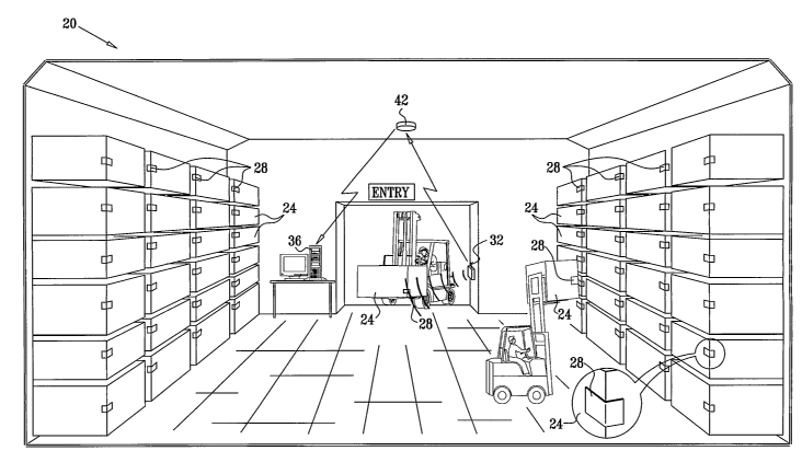
Fig. 1 is a diagram that pictorially illustrates an RFID system 20, in
accordance with an
embodiment of the present invention. System 20 in this example, which is no
way limiting is a
warehouse inventory tracking system, in which objects, such as packages 24 are
stored and
tracked in a warehouse. An RF transponder 28, typically in the form of a tag
or label, is
attached to or is integrally formed with each package 24. The term
"transponder" as used herein
includes, but is not limited to, transponder forms such as tags, labels,
stickers, wristbands,
smart cards, disks or coins, glass transponders, plastic housing transponders,
watch face
transponders and any combination thereof. The term includes any size,
thickness, shape, and
form of transponder device. The term includes integrated and non-integrated
devices, such as,
but not limited to, devices integrated into the packaging of an object or
integrated into the
object or product itself. The term includes transponders, made by any suitable
technology,
including, but not limited to a printing technology.
CA 02572787 2007-01-02
WO 2006/003648 PCT/IL2005/000694
A code comprising information relating to package 24 and/or to transponder 28
can be
generated and stored in a memory of transponder 28. Generally speaking, the
code comprises
any information that is to be transmitted from transponder 28 to reader 32.
For example, the
information may comprise an ID number that identifies package 24. Additionally
or
alternatively, the code may comprise data measured by sensors coupled to the
transponder, or
any other data that should be transmitted to reader 32.
An interrogation device, such as a reader 32, transmits interrogation RF
radiation to
transponder 28 in order to query its information. Typically, the interrogation
radiation
comprises a transverse electromagnetic (TEM) wave. The interrogation radiation
may comprise
interrogation data transmitted to the transponder, such as an identification
of the reader or an
identification of the queried transponder. The transponder receives the
interrogation radiation
and responds by modulating its code onto a backscattered response RF
radiation, using
methods, which will be explained in detail below. The reader receives the
backscattered
radiation and demodulates the code sent by the transponder. The information in
the code can be
transmitted to a processing unit 36. In some embodiments, at least one
repeater 42 can be used
for communicating between reader 32 and processing unit 36, for example in
installations
where there is no line of sight between the reader and the processing unit.
In the example of Fig. 1, a forklift is seen entering the warehouse carrying a
new
package 24 to be stored. Reader 32, in this example configured as a gate
reader, interrogates
transponder 28 attached to package 24 in order to automatically update an
inventory database
maintained by processing unit 36 with the newly-arriving package.
The configuration shown in Fig. 1 is an exemplary RFID application, chosen
purely for
the sake of conceptual clarity: System 20 may comprise any other RFID system,
in which RFID
transponders are coupled to tracked objects. System 20 may comprise, for
example, a container
tracking system, an automatic toll payment system, a book tracking system in a
library, an
airport baggage tracking system, an automatic cashier in a supermarket, animal
tagging, human
tracking such as, but not limited to baby tracking in a hospital or armed
forces tracking, supply
chain management, access control, asset control, total asset visibility,
licensing, product
handshaking, logistics management, movement and theft alarms. System 20 of the
present
invention can be used to monitor assets, packages, containers, and pallets
when they are in
warehouses and stockyards, as well as when they are in transit.
System 20 typically comprises multiple transponders 28 and may comprise
multiple
readers 24 and/or multiple processing units. Reader 32 and transponder 28 may
communicate
using any suitable protocol. An exemplary protocol is defmed in an EPCglobal
specification
entitled "Class-1 Generation-2 UHF RFID Conformance Requirements Specification
v.1Ø2,"
11
CA 02572787 2007-01-02
WO 2006/003648 PCT/IL2005/000694
which is available at www.epeglobalinc.org/standards-technology/
specifications.html.
Another exemplary protocol is the ISO 18000-6:2004 standard entitled "Radio
Frequency
Identification for Item Management - Part 6: Parameters for Air Interface
Communications at
860 MHz to 960 MHz," published by the International Organization for
Standardization (ISO).
The ISO/IEC 18000-6:2004 standard is available at www.iso.org.
The modes of operation of transponder 28 and the functionality of each mode
can be
defined in accordance with any suitable protocol, standard or interoperability
interface, such as
the EPCglobal and ISO specifications cited above.
In some embodiments, system 20 may comprise multiple readers 32. The multiple
readers may be synchronized or non-synchronized. The multiple readers may be
connected to a
single processing unit 36 or to multiple processing units. Interrogation
radiation from more
than one reader may cause mutual interference problems. In some embodiments,
readers 32 of
system 20 can use a "listen before talk" protocol in order to avoid the mutual
interference.
Additionally or alternatively, readers 32 can use synchronized or non-
synchronized frequency
hopping for minimizing interference, as is known in the art.
Reader 32 and processing unit 36 may communicate using any suitable wired or
wireless connection means. Although system 20 can be used in any RFID
application, the
methods and devices described below are particularly suitable for RFID
applications that
require a relatively long range between transponder 28 and reader 32. In
addition, system 20
can be used in a variety of challenging environments, such as environments in
which the
communication path between the transponder and the reader is obstructed by
materials such as
oil, liquids and metals.
Transponder 28 as described herein is a battery-assisted backscatter RFID
transponder.
. The term "backscatter transponder" means that the response radiation is
generated by a
backscattering effect, in which part of the RF energy of the interrogation
radiation is reflected
from the transponder antenna back to the reader. Further, transponder 28 does
not draw current
from an internal battery for generating the RF energy required for
transmitting the
backscattered radiation, thus extending the lifetime of the battery and of the
transponder.
The term "battery-assisted transponder" (sometimes also referred to as a "semi-
active"
or a "semi-passive" transponder) means that power required to run transponder
28 is derived
from an internal power source, such as a battery. In contrast, a passive
transponder does not
make use of an internal power source. The energy for powering the transponder
circuitry in a
passive transponder is derived from the interrogation radiation, which
effectively reduces the
communication range.
12
CA 02572787 2007-01-02
WO 2006/003648 PCT/IL2005/000694
Other transponders, referred to as "active transponders," use the power of the
internal
battery for generating the response radiation. While this configuration may
extend the
communication range of the transponder, the power consumption of an active
transponder is
significantly higher in comparison to a battery-assisted transponder. The
higher power
consumption typically means that an active transponder may either have a
significantly shorter
lifetime, or have a significantly larger size to allow for a larger battery. A
larger battery also
adds to the cost of the transponder.
The background art has described semi-active transponders, in which some of
the
energy of the interrogation radiation received by the antenna is transferred
to the transponder,
absorbed or otherwise made unavailable for backscattering. Since such a
configuration reduces
the energy that is available for backscattering, the communication range of
the transponder is
reduced accordingly. However, in embodiments described herein, the control
circuitry of the
transponder is powered exclusively by the internal battery. As long as the
battery is able to
supply the required energy, the energy of the interrogation radiation is not
used to power the
transponder. Substantially all of the energy of the interrogation radiation
received by the
antenna is thus available for backscattering. Therefore, the configuration
described herein
maximizes the backscatter communication range between the transponder and the
reader.
Transponder 28 can take the form of a tag or a label that is attached to the
tracked
- object. Alternatively, in some cases the transponder may be incorporated as
part of the tracked
object itself. In other cases the transponder can be embedded inside a smart-
card. Further
alternatively, the transponder can be formed and packaged in any other
suitable configuration,
as required by its functionality in system 20. An exemplary mechanical
configuration, in which
transponder 28 is formed as a flexible label, is. shown in Fig. 8 below.
Transponder 28 can be
produced at low cost and thus may be disposable.
In some embodiments, transponder 28 is configured to operate at a temperature
range of
from about -20 C to about 65 C and a non-condensing humidity range of from
about 5% to
about 95%. In some embodiments, transponder 28 is resistant to liquids and
other non-
corrosive materials. In some embodiments, transponder 28 facilitates improved
communication
compared to passive transponders in the presence of RF absorptive and
reflective materials.
The code stored in transponder 28 may conform to any suitable structure,
standard or
convention. For example, the code may comply with the Electronic Product
CodeTM, an
industry-driven standard developed by EPCglobal, Inc. Further details
regarding this standard
can be found at www.epcglobalinc.org. An exemplary product identification
convention is the
EAN.UCC standard. Details regarding this standard are available at www.ean-
ucc.org. In some
embodiments, reader 32 may write input data into transponder 28 in addition to
reading the
13
CA 02572787 2007-01-02
WO 2006/003648 PCT/IL2005/000694
code, as part of the interrogation process. The written data can later be read
by the same reader
or by a different reader in subsequent interrogations.
In some embodiments, the interrogation radiation and the backscattered
radiation are
transmitted in the ultra-high frequency (UHF) range, typically between about
300 and about
3000 MHz, although other suitable higher or lower frequency ranges, such as
for example
microwaves can also be used. Nothing herein is meant to limit the invention
disclosed herein to
operation within the UHF band. The particular choice of frequencies may depend
upon national
spectrum allocation and other regulatory and functional constraints. For
example, typical
frequency ranges are in the range of about 800-900 MHz in Europe and in the
range of about
900-950 MHz in North America. In some embodiments, the same transponder can be
configured to be operable in different frequency bands depending on geography.
As such, the
present invention readily facilitates seamless operation across the globe.
When reader 32 transmits information or other commands to the transponder, the
transmission can use any suitable modulation type, such as amplitude shift
keying (ASK),
frequency shift keying (FSK), single sideband (SSB), double sideband (DSB) and
phase shift
keying (PSK) modulation.
Fig. 2 is a block diagram that schenlatically illustrates details of RFID
system 20, in
accordance with an embodiment of the present invention. Transponder 28
comprises a substrate
48, which serves as the base for mounting the various transponder components.
An antenna 52
receives and backscatters the interrogation radiation transmitted by reader
32. In some
embodiments, the transponder may comprise two or more antennas for improved
coverage.
An integrated circuit (IC) 56, typically an application-specific IC (ASIC),
performs the
various processing and logic functions of transponder 28. In some embodiments,
some
functions of,.IC 56 are implemented using discrete components that are
disposed on substrate
48 as part of the transponder production process.
IC 56 is powered by a battery 60. The RF energy of the interrogation radiation
is
typically detected, amplified, filtered and demodulated by a
detector/demodulator 62 in IC 56.
Detector/demodulator 62 detects the presence of the interrogation radiation
and demodulates
the interrogation data, if such data is transmitted by reader 32.
Detector/demodulator 62 may
use constant false alarm rate (CFAR) techniques known in the art, or any other
suitable method,
for detecting the presence of the interrogation radiation in the presence of
clutter, background
noise and/or interference. In some embodiments, the detector and demodulator
may be
integrally formed in one circuit. Alternatively, the detector and demodulator
may use separate
components or may share some components.
14
CA 02572787 2007-01-02
WO 2006/003648 PCT/IL2005/000694
A control module 64 typically receives an indication regarding the presence of
the
interrogation radiation, and optionally the demodulated interrogation data,
from
detector/demodulator 62. Control module 64 retrieves the transponder code, as
defined above,
which has been previously stored in a memory 66, and sends the code to a
modulator 68, which
accordingly modulates the RF radiation that is backscattered from antenna 52
to reader 32.
Battery 60 may comprise one or more suitable energy sources. The battery may
optionally include circuitry configured to increase or otherwise control the
supplied voltage. In
some embodiments, battery 60 comprises at least one thin and flexible battery,
such as the
batteries produced by Power Paper Ltd. (Petah-Tikva, Israel). Such thin and
flexible batteries
are described, for example, in U.S. Patents 5,652,043, 5,897,522 and
5,811,204, whose
disclosures are incorporated herein by reference. Additional details can also
be found at
www.powerpaper.com. Thin batteries of this sort are typically less than 1 mm
thick.
In some embodiments, the transponder is typically less than 1 mm thick and has
a
bending radius of less than 25 mm. In some embodiments, the transponder is
less than 0.6 inm
thick. In some embodiments, the transponder had a bending radius of less than
50 mm.
In some embodiments, the thin and flexible battery comprises a first insoluble
negative
electrode, a second j insoluble positive electrode, and an aqueous electrolyte
being disposed
between the negative electrode and positive electrode. The electrolyte layer
typically comprises
(a) a deliquescent material for keeping the open cell wet at all times; (b) an
electroactive
soluble material for obtaining required ionic conductivity; and (c) a water-
soluble polymer for
obtaining a required viscosity for adllering the electrolyte to the
electrodes. In some
embodiments, the two electrode layers and the electrolyte layer are typically
arranged in a co-
facial configuration. Alternatively, the two electrode layers and the
electrolyte layer can also
be arranged in a co-planar configuration. The resulting batteiy can facilitate
an even thinner
transponder.
In otller embodiments, battery 60 comprises a thin and flexible battery as
described in
US Patent Application Publication 20030165744 Al, whose disclosure is
incorporated herein
by reference.
In some embodiments, as described in detail hereinbelow, when battery 60 is a
thin and
flexible battery as described above, the different layers of the battery are
deposited on substrate
48 as part of the transponder production process. In alternative embodiments,
a previously
assembled thin and flexible battery is applied or attached to substrate 48.
In some embodiments, battery 60 may be kept in an inactivated state in order
to
increase the longevity of the battery. Such a case may be desirable for a
transponder 28, which
CA 02572787 2007-01-02
WO 2006/003648 PCT/IL2005/000694
manufactured, but is not yet in use. Any suitable method of facilitating an
inactivated state may
be used, such as but not limited to use of a tab over the battery.
In some embodiments, control module 64 comprises a microcontroller core that
runs
suitable software, coupled with peripheral logic and memory. Alternatively or
additionally,
control module 64 may comprise logical functions and management functions
implemented in
hardware as part of IC 56. Memory 66 may comprise any suitable non-volatile or
battery-
backed memory, such as an electronically erasable programmable read only
memory
(E2PROM). Battery-backed memory is sometimes advantageous due to its low
working voltage
and current and low cost.
In some embodiments, memory 66 comprises a read memory section 67, in which
module 64 stores the code and reads it during its transmission to the reader,
and a write
memory section 69, which is used for storing data sent to the transponder from
the reader. In
some embodiments, the read and write memory sections can be activated and
deactivated
independently as appropriate, in order to reduce the energy drawn from battery
60.
In some embodiments, the code is written permanently into memory 66 as part of
the IC
fabrication process or as part of the transponder production process. In other
embodiments, the
code can be written and modified by reader 32 during operation. In some
embodiments, writing
the code into the memory requires the use of a password or a suitable security
code. The
modulator modulates the retrieved code onto the backscattered radiation, which
is
backscattered from antenna 52 to reader 32. The modulation method is described
in detail
hereinbelow.
In some embodiments, transponder 28 comprises authentication and/or encryption
means, for verifying the identity of the transponder and/or of the tracked
object to the reader.
IC 56 may also comprise an energy saving module 70. Module 70 enables and
disables
different hardware functions and components of transponder 28, in accordance
with the
transponder's mode of operation, so as to minimize the current drawn from
battery 60 and
extend its lifetime. Module 70 can use a battery status indicator 72 for
assessing the status of
battery 60. Module 70 is typically implemented as a state-machine using
hardware, software or
a combination of both. The operation of module 70 is shown in detail in Figs.
6A, 6B and 7
below.
In some embodiments, IC 56 comprises a real-time clock (RTC) 74. In some
embodiments, the transponder reads the RTC and adds a time-stamp to the code
sent to the
reader. In some embodiments, transponder 28 senses one or more local
conditions using one or
more external sensors 78. For example, sensors 78 may sense the temperature or
other
16
CA 02572787 2007-01-02
WO 2006/003648 PCT/IL2005/000694
environmental conditions in the vicinity of transponder 28. Sensors 78 may
also comprise
motion sensors, tamper sensors, shock/vibration sensors, humidity sensors,
radiation sensors,
chemical sensors, gas or fume sensors, weight sensors, drug (narcotics)
sensors, explosives
sensors or any other suitable sensor.
Some of sensors 78 may have digital or discrete outputs, whereas other sensors
may
have analog outputs. In some embodiments, IC 56 comprises an analog to digital
converter
(ADC) 76 that samples the outputs of the analog sensors and provides the
sampled values to
control module 64. In some cases, at least one sensor, such as a temperature
sensor, can be
implemented internally to the IC. In some embodiments, at least one sensor can
be
implemented externally to IC 56.
In some embodiments, the information of sensors 78 and RTC 74 is combined to
provide time-dependent alarm conditions. For example, IC 56 may report an
alarm to the reader
if the local temperature exceeds a predetermined threshold for a predetermined
time duration.
The reported alarm can also contain a time-stamp indicating the time of the
event. In some
embodiments, the profile of the sensor measurements over time can be recorded
in memory 66
while the tracked object is outside the reader communication range. A sensor
profile such as a
time-temperature profile is important in applications such as fresh food
packages, medical
supplies, drugs and any other temperature-sensitive commodity. In some
embodiments, control
module 64 can also activate, deactivate or otherwise control parts of the
tracked object in
accordance with commands received from the reader.
Transponder 28 can optionally comprise a display, such as, but not limited to
a light-
emitting diode (LED) or a liquid crystal display (LCD), not shown in the
figures. The display
may comprise an indicator element, such as, but not limited to a color
changing element. In one
non-limiting example, the indicator may readily facilitate a color change in
the event of a
product being out of date or if environmental conditions such as temperature
have exceeded a
specified limit.
In some embodiments, the IC comprises a power-on-reset (POR) and watchdog
timer
(WD) module 80. The POR typically resets control module 64 when power is
applied. The
watchdog timer typically resets a microcontroller in control module 64, when
such a
microcontroller is used, in certain software failure scenarios.
In some embodiments, the functions of IC 56 can also be performed by two or
more
application-specific or general-purpose components.
Figs. 3A-3C are diagrams that schematically illustrate different exemplary
implementations of antenna 52, in accordance with embodiments of the present
invention.
Typically, the type of antenna chosen, as well as its configuration and
dimensions, are
17
CA 02572787 2007-01-02
WO 2006/003648 PCT/IL2005/000694
dependent upon the operating frequency and upon the desired size and shape of
the
transponder. Antenna 52 may comprise a monopole, a dipole, a patch, an array,
or any other
suitable antenna type, as appropriate for the specific configuration of
transponder 28. In some
embodiments, parts of the antenna may be bent or otherwise oriented to fit
within the allocated
space on substrate 48.
Fig. 3A shows an exemplary dipole antenna 90 comprising two elements having
bent
tips that are fed at a feed-point 92. In this embodiment, which is optimized
to give maximal
backscatter and maximal modulation depth at a frequency of 900 MHz, each
element is 102
mm long, of which 42 mm are bent at a 900 angle. In an alternative exemplary
embodiment,
also optimized to operate at 900 MHz, the total length of each element is
still 102 mm, but the
bent section is longer, such as 67 mm. In alternative embodiments, different
total lengths and
different lengths of bent tips can be used to suit the desired transponder
size. A straight dipole
with no bent tips can also be used if sufficient length is available on
substrate 48.
Fig. 3B shows an exemplary monopole antenna comprising an active element 94
and a
ground plane 96. Feed-point 92 is located at the bottom of the active element,
between element
94 and ground plane 96. The total length of element 94 is again 102 mm, to
maximize
backscatter and modulation depth at the operating frequency of 900 MHz. As
with dipole
antenna 90, the tip of active element 94 of the monopole antenna is seen to be
bent, to fit within
the allocated geometry of transponder 28. Different amounts of bending; and in
particular a
straight monopole without bending, can also be used if sufficient length is
available.
Antenna 52 may be deposited on substrate 48 using any suitable method, such as
a
thick-film deposition method, a printed circuit board (PCB) production method,
an etching
process, by printing an electrically-conductive ink, using a metallic foil,
using a vaporization
method, or using any other suitable method known in the art.
Fig. 3C shows an alternative configuration of transponder 28, in which the
components
of transponder 28 are located on two different surfaces of package 24. In some
practical cases,
it is desirable to locate antenna 52 on a narrow surface 97 of the package (or
other object) that
is too narrow to fit the entire transponder. For example, a surface 98,
although wide enough for
fitting the transponder, is sometimes made of a metallic material that
interferes with the
radiation pattern of antenna 52. Two such exemplary cases are compact disk
(CD) packages
and some medication packages. In another case, the tracked object may not
include any surface
wide enough to fit the entire transponder.
In these cases, transponder 28 can be mounted so as to wrap around a corner of
package
24. The transponder is thus attached to two different surfaces of the package,
as shown in the
figure. As will be shown below, substrate 48 and the other layers of
transponder 28, including
18
CA 02572787 2007-01-02
WO 2006/003648 PCT/IL2005/000694
antenna 52 and battery 60 are typically flexible enough to be wrapped around
the corner in the
manner shown or in any other suitable manner, which can facilitate an improved
radiation
pattern. In the example of Fig. 3C, antenna 52, in this case a straight dipole
antenna, is located
on narrow surface 97 together with IC 56. Battery 60 is located on surface 98
and
interconnected to the IC. In other embodiments, the IC may be separate from
the antenna and
located on the same surface as the battery.
In some embodiments, part of the tracked object can be made from a suitable
material,
which can function as antenna 52 or part thereof. In one non-limiting example,
part of a
metallic crate, to which transponder 28 is attached, can be used as a
radiating element or as a
ground plane of the antenna.
When designing antenna 52 of transponder 28, it is typically desirable that
the antenna
radiation pattern be as close as possible to a spherical pattern. A spherical
radiation pattern
enables the reader to communicate with the transponder from any direction,
within the specified
communication range. In some embodiments, antenna 52 is orientation
insensitive, such that it
can operate in any position relative to the direction of the reader antenna.
Nulls in the antenna
radiation pattern typically cause "dead angles," in which the communication
range between the
reader and the transponder is significantly reduced. In some embodiments,
antenna 52 is
optimized to provide a maximum RCS and a maximum modulation depth (ORCS)
during
backscatter modulation, as described hereinbelow.
Fig. 4A is a diagram that schematically illustrates a 3 -D radiation pattern
100 of antenna
52, in accordance with an embodiment of the present invention. The figure
plots the radiation
pattern of the monopole antenna illustrated in Fig. 3B above. For each angular
direction in 3-D
space, the plot shows the achievable reading range between reader 32 and
transponder 28. In
many practical implementations, a true spherical radiation pattern is
difficult to achieve and
often results in a significant loss of gain. In some embodiments, a doughnut-
shaped pattern,
such as pattern 100, is typically considered a good approximation.
Fig. 4B is a graph that schematically illustrates coverage of the monopole
antenna, in
accordance with an embodiment of the present invention. A plot 102 shows the
percentage of
3-D angles that are covered by the radiation pattern of Fig. 4A, per each
communication range.
For example, at a communication range of 6.7 m, 95% of the 3-D angles are
covered. In other
words, when the distance between reader 32 and transponder 28 is 6.7 meters,
communication
will be available at 95% of the possible reader directions. At a distance of
19.3 meters,
approximately 30% of the directions are covered.
19
CA 02572787 2007-01-02
WO 2006/003648 PCT/IL2005/000694
BACKSCATTER MODULATION
Transponder 28 uses backscatter modulation for modulating the code onto the
backscattered radiation transmitted to the reader. The ratio between the total
RF power (of the
interrogation radiation) irradiated onto antenna 52 and the total RF power
that is backscattered
from antenna 52 is referred to as the Radar Cross-Section (RCS) of antenna 52.
Modulator 68 of transponder 28 may receive from control module 64 a serial
binary
sequence, representing the information that is intended to be transmitted to
the reader. The
modulator modulates the RCS of antenna 52 responsively to this binary
sequence. As a result,
the amplitude of the backscattered radiation is modulated accordingly. Any
suitable bit rate can
be used when modulating the antenna RCS. For example, the EPCglobal
specification cited
above defmes bit rates in the range of 40-640 kbps for the link from the
transponder to the
reader. Other applications use lower bit rates, in the range of about 1-3
kbps. Alternatively, any
other suitable bit rate can be used.
As will be explained in detail below, control module 64 and modulator 68 are
typically
inactivated when interrogation radiation is not sensed by the transponder. In
particular,
backscatter modulation is performed only when the interrogation radiation is
present. Reader
32 receives the backscatter-modulated radiation, demodulates and extracts the
code, and
forwards the information to processing unit 36.
Typically, inodulator 68 switches the RCS between two values, referred to as
"RCS
high" and "RCS low," corresponding to the 1's and 0's of the binary sequence
that represents
the code. Typically, modulator 68 uses binary amplitude shift keying (ASK) to
modulate the
value of the antenna RCS. In alternative embodiments, the modulator can
modulate the antenna.
RCS with more than two values, such as using quaternary-ASK modulation.
When transponder 28 performs backscatter modulation, only the energy of the
interrogation radiation is used, for generating the backscattered radiation.
In particular,
transponder 28 uses the electrical power of battery 60 merely for modulating
the antenna RCS,
and not for generating the energy required for backscattering, thus extending
the lifetime of the
battery and of the transponder.
Typically, modulator 68 varies the RCS of antenna 52 by varying the impedance
at
feed-point 92. A first impedance value is set, so that the amount of power
that is backscattered
from the antenna is minimized, thus providing the "RCS low" state. A second
impedance value
is set, so as to maximize the power that is backscattered by the antenna,
thereby producing the
"RCS high" state. In one embodiment, the modulator provides the "RCS high"
state by
producing an open circuit at the antenna terminals. The open circuit condition
causes
substantially all of the power of the interrogation radiation received by the
antenna to be
CA 02572787 2007-01-02
WO 2006/003648 PCT/IL2005/000694
backscattered. Therefore, the communication range between the transponder and
the reader is
maximized.
Controlling the impedance at the feed-point of antenna 52 enables the
modulator to
control the absolute RCS values of the antenna, as well as the ratio between
"RCS high" and
"RCS low" values. This ratio is denoted ARCS, sometimes also referred to as
the modulation
depth.
In some embodiments, the antenna and the modulator are jointly designed so as
to
comply with two conditions simultaneously. Maximizing the amount of
backscattered power
(also referred to as a "backscatter gain" or "backscatter value") in the "RCS
high" state causes a
maximization of the transponder communication range. At the same time,
maximization of the
modulation depth (ARCS) enables the reader to differentiate between
transmitted l's and 0's, so
as to reliably demodulate the code from the backscattered radiation.
Typically, the antenna can
be optimized for maximum RCS and ORCS only within the geometrical constraints
and
available size in transponder 28.
In some passive and battery-assisted transponders described in the background
art that
use interrogation radiation power for operating the transponder, the circuitry
that interfaces to
the antenna also comprises means for rectifying or otherwise drawing energy
from the
interrogation radiation. In other words, the antenna is loaded by the
transponder power supply
or energy conversion circuitry. Such energy conversion circuitry typically
introduces additional
parallel resistance and capacitance across the antenna, which significantly
reduce the antenna's
backscattering performance. Transponder 28, on the other hand, does not draw
power from
antenna 52 for powering the IC. Therefore, antenna 52 and its matching can be
optimized for
maximum backscattering efficiency and modulation depth without such additional
constraints.
In some embodiments, the 'backscattering efficiency of transponder 28 is
typically
higher than 75%, and in many cases higher than 95%. The backscattering
efficiency is defined
as the ratio between the total power that is backscattered from the antenna
and the total power
of the interrogation radiation that is received by the antenna. In other
words, a backscattering
efficiency of 95% means that 5% of the power of the interrogation radiation
received by the
antenna is unavailable for backscattering, and 95% of the received power is
backscattered.
In some embodiments, the modulator comprises a solid-state switch, which is
operatively coupled to the antenna terminals, typically at or near feed point
92. The switch
changes the value of the impedance that loads antenna 52 at the antenna feed-
point, thus
modulating the RCS of the antenna, as explained above.
21
CA 02572787 2007-01-02
WO 2006/003648 PCT/IL2005/000694
Switch 82 may comprise a field-effect transistor (FET), a Gallium-Arsenide
switch, a
PIN-diode switch, or a switch produced using any other suitable switching
technology. The
switching time of the switch is typically below 50 ns. In some cases, a high
RCS can be
produced by making the input impedance of the IC a low real load (i.e., a low
resistance). A
low RCS can typically be obtained by loading the antenna with a real
(resistive) load that is
matched to the impedance of the antenna. It should be noted, however, that the
physical size of
the antenna has a major effect on the achievable RCS values. Exemplary
impedance values for
switch 82 are as follows:
RCS high RCS low
Resistance <_ 100 >_ 100052
Parallel capacitance < lpF <_ 0.25 pF
Assuming a half-wavelength antenna, such impedance values cause "RCS -high
and
"RCS low" values of approximately -1 dB and approximately -20 dB,
respectively.
Alternatively, any other suitable impedance values can be used.
Considering the radiation pattern of antenna 52, the "RCS high" and "RCS low"
backscatter modulation states cause antenna 52 to have two different
backscatter values in any
angular direction. The communication range between transponder 28 and reader
32 typically
varies with the azimuth and elevation angle of the reader relative to the
transponder antenna.
Figs. 5A-5C are graphs that schematically illustrate "RCS high" and "RCS low"
backscatter values of RFID transponder antennas as a function of frequency, in
accordance with
embodiments of the present invention. Fig. 5A shows the backscatter values of
bent dipole
antenna 90 shown in Fig. 3A above (with 42 mm bent tips). A plot 106 shows the
backscatter
value of dipole 90 in the "RCS high" state, plotted as a function of
frequency. The backscatter
value is expressed in dBi, or dB compared to an ideal isotropic radiator. A
plot 108 shows the
backscatter value of the same dipole antenna, when switched to the "RCS low"
state by the
modulator. In examining plot 106 it can be seen that the antenna and its
matching are designed
so that the backscatter gain in the "RCS high" state is maximized at the
operating frequency of
900 MHz, being approximately -7.5 dB. In plots 106 and 108 it can be seen that
ARCS (the
difference between the values of plot 106 and plot 108 at a particular
frequency) is also
maximized at 900 MHz, being approximately 4 dB.
Fig. 5B shows the backscatter value of bent dipole antenna 90 with 67 mm bent
tips. A
plot 110 shows the backscatter value of the antenna in the "RCS high" state,
and a plot 112
shows the backscatter value in the "RCS low" state. Again, the gains are
plotted as a function
of frequency and expressed in dBi. As in Fig. 5A, it can be seen that the
backscatter value in
22
CA 02572787 2007-01-02
WO 2006/003648 PCT/IL2005/000694
the "RCS high" state is maximized at 900 MHz, being approximately -12 dB. The
value of
ARCS is also maximized at 900 MHz, being approximately 6 dB.
Fig. 5C shows the backscatter value of the monopole antenna shown in Fig. 3B
above.
A plot 114 shows the backscatter value of the monopole antenna in the "RCS
high" state, and a
plot 116 shows the backscatter value in the "RCS low" state. Both ARCS and the
backscatter
value in the "RCS high" state are maximized at 900 MHz, being approximately -8
dBi and 7.5
dB, respectively.
OPERATIONAL MODES AND ENERGY SAVING
Figs. 6A and 6B are flow charts that schematically illustrate methods for
communicating between reader 32 and RFID transponder 28, in accordance with
embodiments
of the present invention. Transponder 28, as part of RFID system 20, can
operate in various
operating modes and sequences. The operating modes may be defined, for
example, by the
particular protocol or standard used by system 20, such as the EPCglobal
standard cited above.
The specific set of operating modes used by transponder 28, as well as the
various triggers or
conditions for transitions between modes, are typically defined in control
module 64 and in
energy saving module 70 in IC 56.
Although Figs. 6A and 6B below describe two possible sets of operating modes,
these
are shown purely as clarifying examples. Many other mode definitions and
sequences can be
implemented in transponder 28 and in system 20 in general. Such defmitions
will be apparent
to those skilled in the art and are considered to be within the scope of the
present invention. In
particular, Figs. 6A and 6B serve to demonstrate the operation of energy
saving module 70 in
IC 56. For each operating mode defined for transponder 28, module 70 activates
only the
required hardware functions of transponder 28, so as to minimize the current
drawn from
battery 60.
Energy saving module 70 also comprises timeout timers that determine maximum
time
durations that the transponder is allowed to stay in for each operational
mode. These timers
typically expire under abnormal operating conditions, such as when
communication failures
occur. Typically, when a timeout condition expires, the transponder returns to
a "sleep mode,"
which consumes little current from battery 60. The use of timeout conditions
thus further
extends the lifetime of battery 60. The timeout mechanisms can be implemented
in hardware,
software or a combination of both. Since in some operational modes control
module 64 is
disabled, timeouts that are associated with such operational modes are
typically implemented in
hardware.
23
CA 02572787 2007-01-02
WO 2006/003648 PCT/IL2005/000694
Generally speaking, transponder 28 and reader 32 can be operated in two
different
regimes or protocols, referred to as Transponder-Talks-First (TTF) and Reader-
Talks-First
(RTF). In TTF operation, when the transponder senses the presence of the
interrogation
radiation, it begins to transmit its code, typically at random intervals. In
RTF operation
(sometimes referred to as Interrogator-Talks-First, or ITF), the reader has to
explicitly instruct
the transponder to transmit its code, as part of the interrogation process.
Fig. 6A shows a method that is typical of TTF operation. The method begins
with
transponder 28 in a "sleep mode," at a standby step 120. The transponder
continually checks for
the presence of interrogation radiation, at a detection step 118 and a reader
detection step 119.
Until such presence is detected, the transponder remains in sleep mode.
Typically, when in
sleep mode, energy saving module 70 activates only minimal hardware functions
and draws
minimal current from battery 60. For details regarding the different energy
saving states and the
operation of module 70, see Fig. 7 below. In some embodiments, in which the
transponder
comprises RTC 74, RTC 74 can be energized at all times by the transponder
battery, even when
the transponder is in sleep mode.
In some embodiments, the RF detector in detector/demodulator 62 is configured
to
distinguish between noise and TEM radiation. By detection, distinction and
level measurement
of noise and signal, the RF detector can readily facilitate changing its
detection sensitivity
accordingly, such as changing a signal detection reference level in relation
to the noise. As
such, the RF detector ensures that the device will not be operated by the
noise and avoids
unnecessary drawing of energy from battery 60.
When interrogation radiation is detected at step 119, the transponder can
enter a semi-
active mode, at a semi active operation step 121. The transponder can check
whether a semi-
active timeout expires, at'a semi-active expiry step 122. If the timeout
expires, the transponder
can return to sleep mode at step 120.
After entering the semi-active mode, the transponder can activate read memory
section
67 in memory 66, at a read activation step 123. The read memory is activated
to allow the
transponder to read its code from memory 66. The transponder can read the code
from memory
66 and can transmit it to the reader using backscatter modulation, at a code
transmission step
124. Typically, the transponder repeats transmitting the code at random or
pseudo random
intervals, to avoid collision with transmissions from other transponders.
Alternatively, any
other suitable anti-collision protocol may be adopted by the transponder.
Module 70 comprises
a code transmission timeout counter that determines the maximum time interval
or the
maximum number of repetitions for transmitting the code. Once the code
transmission timeout
expires, the transponder can return to sleep mode at step 120.
24
CA 02572787 2007-01-02
WO 2006/003648 PCT/IL2005/000694
After transmitting its code to the reader, the transponder can check for
incoming
interrogation data from the reader, at a data checking step 125. If such data
exists, the
transponder can receive the interrogation data, at an interrogation reception
step 126. The
interrogation data may comprise incoming data to be written to memory 66, or
commands
affecting the operation of the transponder.
The transponder can check whether the interrogation data comprises a "go to
sleep"
command, at a sleep checking step 127. If instructed to go to sleep, the
transponder can return
to step 120. The transponder can check whether the interrogation data
comprises a message
acknowledging the reception (ACK) of the code by the reader and completion of
the
transponder's function (also referred to as an "ID validated" message), at a
code validation
checking step 128. If such a command is received, the transponder can continue
to decode the
interrogation data at step 126.
Otherwise, the transponder can check whether the interrogation data comprises
a
"write" command, at a write checking step 129. If a write command is detected,
and a write
mode timeout is not expired, the transponder can activate write memory section
69 in memory
66, at a write activation step 132. The transponder can check for subsequent
data transmitted
from the reader, at a data checking step 130. If such data is received, the
transponder can write
the data into memory 66, at a writing step 133. Then, the transponder can
return to sleep mode
at step 120. The write mode timeout timer, checked at a write mode checking
step 131, can
limit the write mode duration in case of communication failure.
If no data is detected, the transponder can return to step 124 and can
continue to
transmit its code and check for data or commands, until the semi-active mode
timeout at
module 70 expires. Then, the transponder can return to sleep mode at step 120.
Fig. 6B shows an alternative method, which is typical of RTF operation. A
basic
difference between TTF and RTF operation is that in RTF, once the presence of
a reader has
been detected, the transponder begins to listen to the reader and check for
data or commands.
The method begins with transponder 28 in "sleep mode," at standby step 120.
Once a
reader is detected at reader detection step 119, the transponder can enter the
semi-active mode
at semi-active operation step 121. If the semi-active mode timeout expires, as
checked by semi-
active expiry step 122, the transponder can return to sleep mode at step 120.
Otherwise, the transponder can begin to receive and decode the interrogation
data
transmitted by the reader, at a decoding step 134. If the received
interrogation data comprises a
"go to sleep" command, as checked by a sleep checking step 135, the
transponder can return to
sleep mode at step 120. Otherwise, the transponder can check whether the
interrogation data
comprises a "read" command, at a read checking step 136. If a "read" command
is received, the
CA 02572787 2007-01-02
WO 2006/003648 PCT/IL2005/000694
transponder can check whether the read command is addressed to it, or to its
group, at an
address checking step 137. If the received "read" command is not addressed to
the specific
transponder 28 or its group, it can return to decoding step 134 and can
continue to decode the
interrogation data.
If the "read" command is appropriately addressed to the specific transponder
or to its
group, the transponder can verify that a read mode timeout in module 70 is not
expired, at a
read mode expiry checking step 138. If expired, the transponder can return to
sleep mode at
step 120. Otherwise, the transponder can activate read memory section 67 of
memory 66 and
can read the code from it, at a reading step 139. The transponder can then
transmit the code
using backscatter modulation to the reader, at a code transmission step 140.
Following sending
the code, the transponder can return to step 134 and can continue to decode
the incoming
interrogation data.
The transponder can check whether the interrogation data comprises an
acknowledgement (an "ID received and validated") message, at a validation
checking step 141.
If such a command is received, the transponder can continue to decode the
interrogation data at
step 134.
The transponder can then check whether the interrogation data comprises a
"write"
command, at a write checking step 142. If a write command is detected, and a
write mode
timeout is not expired, the transponder can activate write memory section 69
in memory 66, at
a write activation step 144. The transponder can check for subsequent data
transmitted from the
reader, at a data checking step 146. If such data is received, the transponder
can write the data
into memory 66, at a writing step 145. Then, the transponder can return to
sleep mode at step
120. The write mode timeout timer, checked at a write mode checking step 143,
can limit the
write mode duration in case of communication failure.
If no data is detected, the transponder can return to step 134 and continue to
check for
and decode the interrogation data, until the semi-active mode timeout at
module 70 expires.
Then, the transponder can return to sleep mode at step 120.
In some embodiments, IC 56 has a fallback mode of operation, in which the
transponder
can operate similarly to a passive transponder when battery 60 is unable to
supply sufficient
power for powering the IC. In these embodiments, the IC can comprise an energy
conversion
circuit 63 comprising a rectifier, a capacitor or similar energy conversion
and/or storage
circuitry for drawing energy from the interrogation radiation. IC 56 typically
comprises one or
more switches for 'switching energy conversion circuit 63 on and off as
needed. (As noted
above, the energy conversion circuit typically reduces the backscatter
efficiency of antenna 52.
26
CA 02572787 2007-01-02
WO 2006/003648 PCT/IL2005/000694
Therefore, it is often desirable to switch the circuit off under normal
battery-assisted operation
and use it only when the battery is not used.)
Energy saving module 70 can check the status of battery 60 using battery
status
indicator 72 and can forward this data to control module 64. If indicator 72
senses that the
battery has insufficient power, for example by sensing that the battery
voltage drops below a
predetermined threshold, module 70 can switch on the energy conversion
circuit. This feature
enables transponder 28 to continue operating as a passive backscatter
transponder, although
typically with a reduced communication range, long after battery 60 is
exhausted.
Figs. 6A and 6B show exemplary operational sequences typical of TTF and RTF
operation, respectively. In some alternative embodiments, the transponder can
use a unified
operational sequence, suitable for both TTF and RTF operation. In such
embodiments, after
detecting the presence of a reader, the transponder typically checks whether
the desired mode or
operation, as indicated by the reader, is RTF or TTF, and performs the
appropriate operational
sequence.
In some embodiments, battery status indicator 130 can include a built in test
(BIT) or
alternatively BIT can be a separate component. The battery status includes,
but it not limited to
built-in test parameters and battery low warning. Built-in test parameters can
include, but are
not limited to, "battery good" indication, "battery low" indication, "battery
needs to be
replaced" indication, estimated and calculated number of possible operations
with battery, and
combinations thereof. In some embodiments, transmission of the battery status
is performed
with every transmission of transponder 28, as part of the code. Alternatively,
the battery status
is transmitted upon request by reader 32.
In some scenarios, the interrogation radiation has excess power, above the
power that is
required for reliably communicating with the reader. Such a condition may
occur, for example,
when the distance between the reader and the transponder is small. In some
embodiments,
when the interrogation radiation has excess power, energy conversion circuit
63 can draw some
or all of the excess power from the interrogation radiation. The transponder
may, for example,
use the excess power for powering IC 56 in parallel with battery 60.
Additionally or
alternatively, the transponder can charge battery 60 using the excess power.
Further
additionally or alternatively, the transponder can make any other suitable use
of the excess
power of the interrogation radiation.
It should be stressed, however, that when using the power of the interrogation
radiation,
first priority is typically given to maximization of the communication range
between the reader
and the transponder at a specified communication reliability. Exploiting the
excess power is
27
CA 02572787 2007-01-02
WO 2006/003648 PCT/IL2005/000694
thus restricted to cases, in which the transponder communication range and
communication
reliability are not compromised.
ENERGY SAVING IN RTF OPERATION
When transponder 28 operates in RTF mode, as required, for example, by the
EPCglobal standards cited above, there is a particular need for efficient
energy saving. The
RTF protocol requires the transponder to continuously listen and check for
data and commands
whenever interrogation radiation is sensed. Since typical RFID systems contain
multiple
transponders and sometimes multiple readers, a particular transponder may
sense interrogation
radiation for a significant percentage of the time. The majority of these
interrogations are
typically intended for other transponders. If the transponder were to fully
activate its circuitry
whenever interrogation radiation is present, its battery life would be
significantly reduced.
Energy saving module 70 in transponder 28 is particularly suitable for
operating in RTF
mode and enables a significant extension of the lifetime of battery 60. In
principle, once
interrogation radiation is sensed by the transponder, the transponder analyzes
the radiation in
order to determine whether or not the radiation is relevant to it. Module 70
progressively
activates components of the transponder, so that only the minimal current is
drawn from battery
60 during the analysis process. Once the radiation is determined to be
relevant (e.g., a valid
interrogation radiation and not noise or interference, or a radiation
addressed to this specific
transponder), module 70 can enable the transponder to transmit the
backscattered radiation or
otherwise react to the interrogation radiation.
In some embodiments, several power saving states are defmed in module 70. Each
operational mode of the transponder, such as the different modes described in
Figs. 6A and 6B
above, is associated with a particular energy saving state. Using the
different energy saving
states, module 70 activates and deactivates the minimal number of hardware
functions, as
required by each operational mode. In an exemplary embodiment, five different
power
management states are defined in module 70, in accordance with the following
table:
Energy saving Transponder Functionality Active hardware Typical
state current
A Check for presence of RF detector in < 0.25 A
interrogation radiation detector/demodulator 62
power
B Search for preamble in Detector/demodulator 62, < 3 A
interrogation radiation preamble identifier in module 64
28
CA 02572787 2007-01-02
WO 2006/003648 PCT/IL2005/000694
C Decode interrogation data Same as in B above, plus a < 5 A
and commands command identifier in module
64
D Read mode (operate full Same as C above, plus module < 10 A
logic and read code from 64 and read memory in memory
memory) 66
E Write mode (operate full Same as D above, plus write < 15 A
logic and write data to memory in memory 66
memory)
Fig. 7 is a state diagram that schematically illustrates an exemplary
mechanism for
energy saving, carried out by module 70 in RTF mode, in accordance with an
embodiment of
the present invention.
The mechanism of Fig. 7 is invoked when transponder 28 senses the presence of
interrogation radiation. This mechanism can be invoked, for example, after
reader detection
step 119 in the method of Fig. 6B above and can replace steps 119-134 of this
method.
Following detection of the interrogation radiation, transponder 28 can check
for the
existence of a predetermined data pattern in the interrogation radiation, in a
pattern checking
state 240. The purpose of step 240 is to avoid activating unnecessary hardware
components
until it is verified that the sensed energy originates from a valid
interrogation radiation of a
reader and not from noise or interference. In state 240, module 70 is in
energy saving state B
(as defined in the table above) and the current drawn from battery 60 is
typically below 3 A at
1.5 volts. State 240 thus enables screening many false alarm events while
drawing minimal
current from the battery.
Once a valid pattern is detected, transponder 28 can demodulate the preamble
of the
interrogation radiation and can check for specific addressing, in an address
verification state
242. The purpose of state 242 is to screen out interrogations that are not
addressed to this
specific transponder, and thus should be ignored. In state 242, module 70 is
in energy saving
state C and the current drawn from battery 60 is typically below 5 A at 1.5
volts. If specific
addressing is not detected within a predetermined timeout interval, the
transponder can return
to state 240.
Once the interrogation is found to be addressed to the specific transponder,
module 70
can activate the hardware necessary for demodulating the full interrogation
data, and can
receive the data in an interrogation demodulation state 244. In state 244,
module 70 is in energy
saving state D and the current drawn from battery 60 is typically below 10 A
at 1.5 volts.
29
CA 02572787 2007-01-02
WO 2006/003648 PCT/IL2005/000694
As can be appreciated from the mechanism described above, state 244 is reached
only
when it is assured that a valid interrogation radiation that is intended for
the specific
transponder is being received. Therefore, the use of this state machine
mechanism reduces
significantly the average current drawn from battery 60 in RTF operation.
In some embodiments, transponder 28 can also change its operational mode in
response
to predetermined timeout conditions. Such conditions are evaluated and
activated by energy
saving module 70. For example:
~ If interrogation radiation is detected for a predetermined duration of time,
but within this
time duration no pattern is detected, the transponder can regard the detected
energy as noise or
interference. Following such an event, module 70 may force the transponder to
ignore
subsequent interrogation detections for a predetermined time interval.
~ If a pattern is detected but no addressing to the specific transponder is
detected within a
predetermined duration of time, module 70 may force the transponder to ignore
subsequent
interrogation detections for a predetermined time interval.
~ Following a successful interrogation and data exchange between the
transponder and the
reader, the transponder may conclude that the reader is not likely to
interrogate it again for a
certain period of time. In such case, module 70 forces the transponder to
ignore subsequent
interrogation detections for a predetermined time interval following a
successful interrogation.
(This condition demonstrates that in some cases, timeout conditions can use
knowledge of the
specific RTF protocol used, in order to save battery energy.)
By using timeout conditions, the transponder is able to spend a higher
percentage of the
time in states that consume less power, thus reducing the average power
consumption from
battery 60. Combining the timeout conditions with the state machine mechanism
shown in Fig.
7 above, the average current consumption from battery 60 is significantly
reduced. The lower
energy consumption can be used to extend the lifetime of the transponder, or
to reduce the size
of battery 60 and further miniaturize the transponder.
RFID TRANSPONDER MECHANICAL STRUCTURE
Fig. 8 is a schematic exploded view of RFID transponder 28, in accordance with
an
embodiment of the present invention. In this example, transponder 28 takes the
form of a thin
and flexible label. In one non-limiting example, the label has a size of
approximately 3 by 5
inches and the label is less than 1 mm thick. The same basic design structure
can be used in
different forms and sizes of battery assisted RFID transponders. The upper
side of Fig. 8
corresponds to the side of the label that is attached to the tracked object.
CA 02572787 2007-01-02
WO 2006/003648 PCT/IL2005/000694
The figure shows substrate 48, which can optionally be any suitable substrate
as
described hereinabove. In some embodiments, substrate is polyester, such as
but not limited to
polyester 75 micron. Antenna 52 is deposited on substrate 48. The antenna in
this example is
the monopole antenna shown in Fig. 3B, which is printed as a metallic layer on
substrate 48.
Both active element 94 and ground plane 96 can be clearly seen in the figure.
In addition to the
antenna, the printed metallic layer comprises conductors that interconnect IC
56 with battery 60
and antenna 52 once they are attached to the substrate. Battery 60, in this
case a Power Paper
battery type STD-3 or STD-4, is attached in a suitable location on top of
ground plane 96. The
battery terminals are connected to the printed conductors by a suitable
connection means, such
as by using a suitable electrically-conductive adhesive 185. IC 56 is attached
in a suitable
location on the substrate and interconnected with the battery and the antenna.
The substrate and the components mounted on it are attached to a liner 186,
such as but
not limited to a silicone liner, using for example a double-sided adhesive
187. When attaching
transponder 28 to package 24 or other tracked object, the silicone liner can
be peeled off, and
the transponder attached to the object using the double-sided adhesive.
A front liner 188 is attached to the bottom side of surface 48. In some
embodiments, the
front liner comprises adhesive polyethylene, a suitable double-sided adhesive
tape.
Alternatively, any other suitable liner can be used. In some embodiments, a
graphic label 189
canbe attached to the front liner. Label 189 may comprise any relevant textual
or graphical
information, such as a company logo or a bar-code.
In some embodiments, additional layers, such as adhesive layers (not shown in
figure)
are applied, which are configured to facilitate uniform thickness of the
transponder label.
In an alternative embodiment, release liner 186 can be disposed on the distal
side of
substrate 48. However, this configuration is not always suitable due to the
proximity of antenna
52 to the packaging of the tracked object.
The resulting transponder structure is small, flat and flexible, enabling it
to easily attach
to different objects and to conform to the shape of the object. In
sufficiently large volumes,
such label is low-cost and can be disposed of after use.
Fig. 9 is a flow chart that schematically illustrates a method for producing
RFID
transponder 28, in accordance with an embodiment of the present invention. A
substrate 48 is
provided, at a substrate provisioning step 190. Substrate 48 can typically be
made of a material
such as polyester or paper. Other examples of substrate materials include
woven materials, non-
woven materials, polymers, conducting materials, non-conducting materials,
cardboard, plastic,
synthetic materials, natural materials, fabrics, metals, wood, glass, Perspex,
a combination
thereof or any other suitable material.
31
CA 02572787 2007-01-02
WO 2006/003648 PCT/IL2005/000694
Optionally, substrate 48 can be made up of a plurality of substrate base
layers that are
stacked or connected in a co-planar way by any suitable attachment
methodology. In an
embodiment, in which substrate 48 comprises a plurality of base layers, each
of the antenna, IC
and battery can optionally be attached to a different substrate base layer.
Optionally, substrate
48 can be of any suitable size, shape or color.
In one embodiment, substrate 48 can be made integral with the tracked object
or its
packaging. For example, substrate 48 can be made an integral part of a
cardboard box, wooden
crate, metal crate, plastic box, metal can, car, etc. In such a way,
transponder 28 can be
produced directly onto an end-product material, which can then optionally be
further processed
to form the tracked object or its packaging. This embodiment facilitates an
integrated RFID
transponder.
In some embodiments, substrate 48 can be implemented to comprise a suitable
attachment means, which readily facilitate attaching transponder 28 to the
tracked object or its
packaging. The attachment means may coniprise but are not limited to,
adhesive, self adhesive
label, hook and loop fastening systems (such as Velcro(M), magnetic
attachment, suction
attachment, ties and combinations thereof.
Antenna 52 is deposited onto substrate 48, at an antenna deposition step 192.
The
antenna may be deposited using a thick-film deposition method, an etching
process, by
attaching a metallic foil or template cut to the appropriate shape, by
printing a suitable
electrically-conductive ink, using a vaporization method, or using any other
suitable deposition
method. In some embodiments, antenna 52 is deposited on the substrate using a
suitable printed
circuit board (PCB) manufacturing process. In these embodiments, substrate 48
comprises a
suitable PCB material with a metallic layer disposed thereon.
IC 56 is placed on substrate 48, at an IC placement step 194. The IC may be
soldered,
glued or otherwise attached to the substrate using any other suitable means.
In one
embodiment, the IC is interconnected with conductors disposed on the substrate
using "flip-
chip" technology, as is known in the art. In this embodiment, the flip-chip
interconnections
function as the mechanical attachment means as well. The conductors may be
deposited on the
substrate together with the antenna at step 192. Typically, the location of
the IC is chosen to be
as close as possible to feed point 92 of antenna 52, so as to maintain the
desired impedance
match or mismatch and to minimize signal losses.
In an alternative embodiment, IC 56 may comprise an organic polymer electronic
chip,
as known in the art. Such a polymer chip is printable and can be printed
directly on substrate
48. The use of such a chip can facilitate production of a fully printable
transponder, in which
the battery, connectors, antenna and chip can be printed onto the substrate.
32
CA 02572787 2007-01-02
WO 2006/003648 PCT/IL2005/000694
In still a fiirther alternative embodiment, a plurality of discrete components
can be used
instead of IC 56. Such discrete components can preferably be produced using a
printing
technology and can be printed on substrate 48. The printable discrete
components can facilitate
production of a fully printable transponder.
Battery 60 is applied to substrate 48, at a battery application step 196. The
battery can
be mechanically attached to the substrate at any suitable location and using
any suitable
attachment means, such as gluing, crimping or soldering. In some embodiments,
the location of
battery 60 is chosen so as to minimize interference with the radiation pattern
of antenna 52. For
example, in the mechanical configuration shown in Fig. 8 above, the battery is
attached over
the area of ground plane 96, so as to minimize the effect on the radiation
pattern of the
monopole antenna.
In some embodiments, when battery 60 comprises a thin and flexible battery
such as the
Power Paper batteries described above, the different layers of battery 60 can
be deposited or
printed on substrate 48 as an integral part of the transponder production
process. In one
exemplary embodiment, substrate 48 of the transponder serves as the substrate
for one of the
electrodes of battery 60, and another substrate is used for the second
electrode. An exemplary
battery and a method for producing such a battery are shown in Figs. 10A and
10B below.
Alternatively, a thin and flexible battery can be assembled separately and
then attached to
substrate 48.
In one optional embodiment, part of the battery may be used as part of or in
place of
antenna 52. For example, the conductive material of one or both of the battery
electrode layers
can function as part of the antenna.
Having deposited the antenna, IC and battery on the substrate, the three
components are
interconnected, at an interconnection step 198. Interconnection of the IC may
use any suitable
IC interconnection means, such as "flip-chip" methods and wire bonding.
Battery 60 can be
interconnected with the other transponder components by direct soldering,
using PCB
conductors or using any other suitable connection means.
In some embodiments, the transponder is activated and tested as soon as the
antenna, IC
and battery are interconnected, at a testing step 200.
Optionally, additional layers are added to the transponder, at a packaging
step 202. For
example, top and bottom liners can be added in order to improve the mechanical
durability of
the transponder and to facilitate the attachment of the transponder to the
tracked object. In some
embodiments, an additional layer is applied underneath substrate 48, in order
to introduce
additional separation between antenna 52 and the surface of the tracked
object. This added
separation may be needed, for example, when the tracked object is metallic,
for reducing
33
CA 02572787 2007-01-02
WO 2006/003648 PCT/IL2005/000694
interference from the tracked object to the radiation pattern of the antenna.
In some cases, an
external lamination is applied to the transponder. Additional items such as a
bar-code or
graphical label can also be added at this stage.
Optionally, the code is written into memory 66 of the transponder, at an ID
writing step
204. Alternatively, the code may be pre-programmed into the memory or stored
in the memory
at a later stage.
Note that steps 190-204 above can be executed in different orders. For
example, when
battery 60 is fabricated as part of the transponder production process, step
196 is inherently
simultaneous with step 198. As another example, testing step 200 can also be
executed after
packaging step 202, when the transponder is fully assembled.
In some embodiments, transponder 28 is particularly suitable for manufacturing
using a
continuous, fully-automated, printing, drying and laminating process. In some
embodiments, a
roll-to-roll process, is used. Such a roll-to-roll process is capable of
efficiently mass-producing
transponders 28. The method described by steps 190-204 above can be readily
adapted to
different transponder configurations and to different manufacturing volumes
and technologies.
Fig. 10A is a schematic exploded view of a printed battery, in accordance with
an
embodiment of the present invention. The printed battery of Fig. 10A is a thin
and flexible 1.5
V cell, which can be used as battery 60 of transponder 28. Some of the battery
elements are
printed using certain inks having the desired chemical composition. Similar
batteries and
production methods are also described in detail in U.S. Patents 5,652,043,
5,897,522 and
5,811,204 cited above.
In this embodiment, battery 60 comprises two current collectors 205 applied to
substrates 206. An anode layer 207 is applied to one current collector and a
cathode layer 208 is
applied to the other current collector.: An electrolyte 209 is applied to
anode layer 207, to
cathode layer 208, or to both. A separator layer 210 is inserted between the
anode and cathode
layers.
Fig. lOB is a flow chart that schematically illustrates an exemplary method
for
producing battery 60 of Fig. 10A, in accordance with an embodiment of the
present invention.
The method described below can be used to implement battery application step
196 of the
transponder production method of Fig. 9 above. In some embodiments, the
battery is
manufactured separately and then integrated into the transponder. In other
embodiments, the
battery is printed and fabricated on the same substrate as transponder 28, as
an integral part of
the transponder production method.
The method comprises printing current collectors 205, at a current collector
printing
step 211. Typically, two current collectors are printed, one for collecting
the anode current and
34
CA 02572787 2007-01-02
WO 2006/003648 PCT/IL2005/000694
one for collecting the cathode current. The collectors are printed on suitable
substrates 206,
such as polyester substrates. (When the battery is printed as part of the
transponder production
process, substrate 48 of the transponder can serve as one of substrates 206.)
In some
embodiments, the current collectors comprise a layer of current collector ink,
for example
Current Collector Ink 2501, P/N 0002.25.01, produced by Power Paper Ltd. The
current
collectors are typically dried after printing using suitable drying means,
such as an oven.
Anode layer 207 and cathode layer 208 are printed on top of the current
collectors, at an
electrode printing step 212. Anode layer 207 typically comprises a suitable
anode ink, for
example a zinc anode ink such as Anode Ink 2101, P/N 0002.21.01, produced by
Power Paper
Ltd. Cathode layer 208 typically comprises a suitable cathode ink, for example
a manganese
dioxide (Mn02) ink such as Cathode Ink 2201, P/N 0002.22.01, produced by Power
Paper Ltd.
After printing, the anode and cathode layers are typically dried after
printing using,.suitable
drying means, such as an oven.
Electrolyte 209 is applied by any suitable means at an electrolyte applying
step 214. The
electrolyte can be applied to anode layer 207, to cathode layer 208, or to
both. In some
embodiments, particularly when a stencil printing process is used, electrolyte
209 may
comprise an electrolyte ink such as Electrolyte 2301, P/N 0002.23.01, produced
by Power
Paper Ltd. In other embodiments, particularly when a screen printing process
is used,
electrolyte 209 may comprise an electrolyte ink such as SP Electrolyte 2302,
P/N 0002.23.02,
produced by Power Paper Ltd. In some embodiments, electrolyte layer 208
comprises zinc
chloride. Alternatively, any other suitable electrolyte material can be used.
Separator layer 210 is placed on top of the electrolyte layer of either the
anode layers or
cathode layers, at a separator insertion step 216. The separator layer
separates the anode layer
from the cathode layer, while allowing ion conductivity between the
electrodes. Typically, the
separator layer comprises a porous insoluble substance, such as, but not
limited to, filter paper,
plastic membrane, cellulose membrane, cloth or non-woven material (e.g.,
cotton fibers).
In an alternative embodiment, separator layer 210 can self-form as a result of
a reaction
and/or an interaction between materials in the two electrolyte layers.
The battery is assembled at a cell assembly step 218. In some embodiments,
this step
can include applying an adhesive frame, such as a pressure sensitive glue
frame, which can be
applied onto the edge of the single cell substrate. This step can further
include laminating the
electrode layers with the separator to the opposite electrode layer without
the separator. In such
a way the substrates, current collectors, electrodes, electrolyte and
separator layers are stacked
CA 02572787 2007-01-02
WO 2006/003648 PCT/IL2005/000694
in the manner shown in Fig. 10A above. In some embodiments, a press, such as
but not limited
to a hot press, is used to press the glue frame for optimal adherence of the
glue frame.
In some embodiments, connectors can be attached to the current collectors as
part of or
following the cell assembly step. The connectors may comprise, for example,
metallic tabs or
strips, double-sided conductive adhesive tape and heat-sealed connectors.
IMPLEMENTATION EXAMPLES
Reference is now made to the following two examples, which together with the
above
descriptions illustrate the invention in a non-limiting fashion. The following
table provides an
exemplary specification of a transponder 28, in accordance with an embodiment
of the present
invention:
Parameter Specification
Operating frequency 860-880 and 902-928 MHz
Frequency hopping operation As authorized for the reader
Optimized antenna RCS 6/?~2 = lm2 for a 10X10 cm label area
Optimized antenna ARCS A6/k2 = 0.9 RCS
Free space read and write range with reader 30 m
effective isotropic radiated power (EIRP) = 4
Watt
Reader to transponder modulation ASK, DSB, SSB, FSK or PSK
Transponder to reader modulation ASK or subcarrier PSK
Reader to transponder data rate 4.8-128 kbit/sec
Transponder to reader data rate 4.8-512 kbit/sec
Reader to transponder coding NRZ, Miller, PIE or PWM
Transponder to reader coding direct or subcarrier, NRZ, FMO or Miller
Basic non-volatile (EEPROM) memory
organization:
UID 64-196 Bits
System Memory 128 Bits
Passwords and CRC 64 Bits
User Memory 120 Bits
Operating temperature -20 - +60 C
Non-damaging RF input at the antenna <+20 dbm
terminal
36
CA 02572787 2007-01-02
WO 2006/003648 PCT/IL2005/000694
An exemplary implementation of transponder 28, in the form of a label, was
tested in
different operating environments. In each enviromnent, the reading reliability
(percentage of
successful interrogations) and reading range were measured. The following
table shows non-
limiting examples of test results for several challenging environments. All
tests used a reader
32 having a single antenna. In particular, some of the test environments
included foils and other
metallic objects in the vicinity of the transponder. Nevertheless, 100%
reading reliability was
achieved in nearly all environments, as can be seen in the table:
Tracked object Test scenario Reading Reading
Reliability (% Range
of labels read (feet)
Metal containers filled Outdoor loading/unloading area 100% Up to 30
with fragrance liquid feet
Aluminum foil juice Distribution center; reader on 100% 10 feet
boxes truck door; 100 boxes on metal
roll containers; container-level
tagging
Canned food Distribution center; reader on 100% 10 feet
truck door; 100 boxes on metal
roll containers; container-level
ta in
Ice cream (at -30 C) Distribution center; reader on 100% 10 feet
truck door; 100 boxes on metal
roll containers; container-level
ta in
Mixed goods (e.g., Reader/gate scenario. Several 100% 10 feet
spaghetti sauce, metallic labels in and around boxes on a
coffee canisters, spicy pallet
sauce in aluminum foil)
Dishwashing detergent Reader/gate scenario. Labels 100% 10 feet
placed around a box holding
boxes of detergent
Baby wipes Labels sandwiched in between 100% 10 feet
individual items
Cigarette packs Item level; one label per pack; 98% N/A
(aluminum foil) conveyer belt test
Beverages (wine, soda Item level; one label per 100% N/A
cans, etc.) bottle/can
Oil lubricant bottles Item level on pallet in several 100% 23-30 feet
layers
Condensed dog food (22 Item level 100% 32 feet
lb. bags)
Wooden blocks Multiple tags staggered on three 100% Up to 40
level wood blocks feet
Although the methods and devices described herein mainly address battery-
assisted
UHF backscatter RFID transponders, the principles of the present invention can
be used for
37
CA 02572787 2007-01-02
WO 2006/003648 PCT/IL2005/000694
additional applications, as well. Such applications include, for example,
electronic article
surveillance (EAS) systems and authentication applications in EAS systems.
It will thus be appreciated that the embodiments described above are cited by
way of
example, and that the present invention is not limited to what has been
particularly shown and
described hereinabove. Rather, the scope of the present invention includes
both combinations
and sub-combinations of the various features described hereinabove, as well as
variations and
modifications thereof which would occur to persons skilled in the art upon
reading the
foregoing description and which are not disclosed in the prior art.
38