Note: Descriptions are shown in the official language in which they were submitted.
CA 02572899 2007-01-04
SPECIFICATION
TITLE OF THE INVENTION
LIP TYPE END FACE SEALING DEVICE
BACKGROUND OF THE INVENTION
Field of the Invention
The present invention relates to a lip type end
face sealing device in which a seal lip is tight
contacted with an end face to carry out sealing.
Description of the Conventional Art
Forexample, Japanese Utility Model Laid-Open No.
6(1994)-49856 discloses a typical conventional
sealing device for tight sealing between engine oil
and clutch oil in a wet type engine.
Fig. 16 is a half cross-sectional view
illustrating a conventional sealing device 100 which
is similar to a device illustrated in Fig. 5 in the
above-described patent document. That is, the
sealing device 100 is made of a rubber-like elastic
material and formed in an annular metal case 101 which
is pressed-in and fitted to an inner peripheral face
of a housing 120. The sealing device 100 includes a
pair of radial seal lips 102 and 103 which are
positioned oppositely to each other in the axial
direction. Extension springs 104 and 105 for giving
fastening force to a rotary shaft 130 are mounted on
1
CA 02572899 2007-01-04
outer peripheries of the radial seal lips 102 and 103.
The one radial seal lip 102 is for sealing engine oil,
and the other radial seal lip103 is for sealing clutch
oil.
However, as for the sealing device 100
illustrated in Fig. 16, the radial seal lips 102 and
103 have the comparatively short life since being
abraded by the fastening force to the rotary shaft 130.
Further, when the radial seal lips 102 and 103 are
mounted in the slight eccentric state to the rotary
shaft 130, parts at circumferential directional sides
of the radial seal lips 102 and 103 have too low sliding
face pressures to the rotary shaft 130 or some spaces
between these seal lips and the rotary shaft 130 are
generated, so that different liquids at both axial
sides may be mixed each other. Further, when the
radial seal lips 102 and 103 are fitted on the rotary
shaft 103 to be mounted, meticulous care is needed not
to damage the radial seal lips 102 and 103.
Further, for solving such the problem, an end face
sealing type end face sealing device as illustrated
in Fig. 1 in the above-described patent document has
been developed in recent years. In this end face
sealing device, a seal lip is slidably contacted with
an end face of a slinger which is vertical to an axis
2
CA 02572899 2007-01-04
of a shaft. However, as for the end face sealing type,
a negative pressure is caused in the seal internal
space by centrifugal force at the time of rotation,
where the space is tight closed by both seal lip sliding
parts. Thus, the seal lip is entirely contacted with
the end face of the slinger so as to increase sliding
load. As a result, sealability may be decreased.
Summary of the Invention
The present invention solves the above-described
problems, and an objective of the present invention
is to provide a lip type end face sealing device having
excellent sealability and excellent durability.
Inordertoeffectivelysolvetheabove-described
technical problems, a lip type end face sealing device
according to a first aspect of the invention comprises
a pair of seal lips being integrally fitted to an
annular case fixed on an inner peripheral face of a
housing, being positioned oppositely to each other in
the axial direction, and being opened in a tapered
shape; a pair of slingers being tight fitted to an outer
periphery of a rotary shaft inserted into the inner
periphery of the housing and being slidably contacted
with the respective seal lips at flange parts; and a
vent passage for releasing pressure in a seal internal
space between sliding parts of the both seal lips and
3
CA 02572899 2007-01-04
the both slingers. Therefore, even when air is
discharged from the seal internal space between the
sliding parts of the both seal lips and the both
slingers by centrifugal force at the time of the
rotation of the slingers, the pressure does not become
negative.
The lip type end face sealing device according
to a second aspect of the invention has, in addition
to the constitution of the first aspect, a constitution
that the case comprises a pair of case members and the
vent passage comprises a vent hole opened on the inner
peripheral face of the housing; and an air hole being
opened at a fitting face with the inner peripheral face
of the housing in the case so as to face between the
pair of case members and being conducted to the vent
hole. That is, the device includes such a
constitution as to release the pressure in the seal
internal space between the sliding parts of the both
seal lips and the both slingers from a space between
the pair of case members constituting the case through
the air hole of the case and the vent hole of the
housing.
The lip type end face sealing device according
to a third aspect of the invention has, in addition
to the constitution of the first aspect, a constitution
4
CA 02572899 2007-01-04
that the vent passage comprises a vent hole opened on
the inner peripheral face of the housing; and a vent
tube of which one end is connected with the vent hole
and another end is conducted to the seal internal space
between the sliding parts of the both seal lips and
the both slingers. That is, the device includes such
a constitution as to release the pressure in the seal
internal space between the sliding parts of the both
seal lips and the both slingers, from the vent tube
through the vent hole of the housing.
The lip type end face sealing device according
to a fourth aspect of the invention has, in addition
to the constitution of the first aspect, a constitution
that the one seal lip is for sealing liquid and the
other seal lip is for sealing dust at the atmosphere
side, the vent passage is formed at the slinger, and
the seal internal space between the sliding parts of
the both seal lips and the both slingers is conducted
to the atmosphere side through a dust filter.
Therefore, the vent passage does not need to be formed
on the housing side, and the air sucked into the
internal space between the sliding parts of the both
seal lips and the both lingers is filtrated by the dust
filter.
A lip type end face sealing device according to
CA 02572899 2007-01-04
a fifth aspect of the invention comprises a seal lip
being integrally fitted to an annular case fixed on
an inner peripheral face of a housing and being opened
in a tapered shape to the sealed liquid side; a slinger
being tight fitted to an outer periphery of a rotary
shaft inserted in the inner periphery of the housing
and being slidably contacted with the seal lip at a
flange part; and a dust cover being tight fitted on
the outer periphery of the rotary shaft so as to be
positioned at the atmosphere side of the slinger and
having a dust lip slidably contacted with the flange
part of the case at an outer periphery side of the dust
cover, and is structured such that the dust cover
comprises a vent passage for releasing pressure in a
seal internal space between sliding parts of the seal
lip and the dust lip to the atmosphere side, and a dust
filter provided in the vent passage. Therefore, even
when the air is discharged by centrifugal force applied
to the sliding part from seal internal space between
a sliding part of the seal lip and the slinger and
between a sliding part of the dust lip and the case,
pressure in the seal internal space is released through
the vent passage, so that the pressure does not become
negative.
The lip type end face sealing device according
6
CA 02572899 2007-01-04
to a sixth aspect of the invention has, in addition
to the constitution of any of the first to fifth aspects,
a constitution that spiral grooves for pumping to the
outer peripheral side by the rotation of the slinger
are formed on a slidably contacting face of the seal
lips and the slingers.
The lip type end face sealing device according
to a seventh aspect of the invention has, in addition
to the constitution of the fifth aspect, a constitution
that the vent passage is formed in a slit shape at the
portion passing through a rubber layer. That is, the
slit shaped portion passing through the rubber layer
is ordinarily closed and operates so as to be opened
when the negative pressure is generated in the seal
internal space. Thus, the dust filter positioned at
the inner side of the vent passage is not constantly
exposed to external dusts, and invading of dusts having
large particles is also prevented.
The lip type end face sealing device according
to an eighth aspect of the invention has, in addition
to the constitution of the fifth aspect, a constitution
that the vent passage spirally extends along a fitting
part with the rotary shaft in an inner peripheral part
of the dust cover. Thereby, a filtration route by the
dust filter in the vent passage can be lengthened.
7
CA 02572899 2007-01-04
The lip type end face sealing device according
to a ninth aspect of the invention has, in addition
to the constitution of the fifth aspect, a constitution
that positioning of an inner peripheral part of the
dust cover is decided by contacting to an end face at
the atmosphere side of the slinger. By this
constitution, in the process of mounting the seal, the
inner peripheral part of the dust cover is contacted
with the end face at the atmosphere side of the slinger
so that positioning of the dust cover to the slinger
can be decided.
A lip type end face sealing device according to
a tenth aspect of the invention comprises a seal lip
being integrally fitted to an annular case fixed on
an inner peripheral face of a housing and being opened
in a tapered shape to the sealed liquid side; a slinger
being tight fitted to an outer periphery of a rotary
shaft inserted in the inner periphery of the housing
and being slidably contacted with the seal lip at a
flange part; and a dust cover being tight fitted on
the outer periphery of the rotary shaft so as to be
positioned at the atmosphere side of the slinger and
having a dust lip slidably contacted with the case at
an outer periphery side of the dust cover, and is
structured such that the dust lip is separated from
8
CA 02572899 2007-01-04
the case by centrifugal force at the predetermined
rotating speed or more so as to release the pressure
in the internal space of the dust cover to an external.
A lip type end face sealing device according to
an eleventh aspect of the invention comprises a seal
lip being integrally fitted to an annular case fixed
on an inner peripheral face of a housing and being
opened in a tapered shape to the sealed liquid side;
a slinger being tight fitted to an outer periphery of
a rotary shaft inserted in the inner periphery of the
housing, and being slidably contacted with the seal
lip at a flange part; and a dust cover being tight
fitted on the outer periphery of the rotary shaft so
as to be positioned at the atmosphere side of the
slinger and having a dust lip slidably contacted with
the case at an outer periphery side of the dust cover,
and is structured such that at least one of the sliding
faces of the dust lip and the case which are slidably
contacted each other is processed with a surface
roughening treatment. Thereby, countless slight
labyrinth-shaped vent passages are formed between the
dust lip and the case.
In the lip type end face sealing device according
to the first to fourth aspects of the inventions, since
the seal lips are tight contacted with the flange parts
9
CA 02572899 2007-01-04
of the slingers, a load according to sliding is low.
Further, since the pressure in the seal internal space
between the sliding parts of the both seal lips and
the both slingers is released through the vent passage,
causing of the negative pressure in the space by the
rotation of the slingers can be prevented. Therefore,
entirely contacting of the seal lips to the slingers
by the negative pressure can be prevented, so that
excellent sealability can be kept for a long period
of time.
Further, in the lip type end face sealing device
according to the fourth aspect of the invention, in
addition to the effect of the first aspect, dusts in
the atmosphere do not invade into the sealed liquid
and a sealing structure can be simplified.
In the lip type end face sealing device according
to the fifth to ninth aspect of the invention, since
the pressure in the seal internal space is released
through the vent passage, entirely contacting of the
seal lip and the dust lip by the negative pressure can
be prevented, so that excellent sealability can be kept
for a long period of time. Further, since the air hole
does not need to be formed at the housing side, the
seal structure can be simplified. Furthermore, since
air sucked into the seal internal space can be
CA 02572899 2007-01-04
filtrated by the dust filter, dusts in the atmosphere
do not invade into the sealed liquid.
In the lip type end face sealing device according
to the sixth aspect of the invention, the spiral groove
can remove the sealed liquid, which may invade from
the outer peripheral side to the sliding parts of the
seal lip and the slinger, by the pumping work generated
by the rotation of the slinger. Therefore,
sealability can be remarkably increased.
In the lip type end face sealing device according
to the seventh aspect of the invention, the dust filter
is not constantly exposed to external dusts and
invading of dusts having large particles can be
prevented. Thus, in addition to the effect of the
fifth aspect, a dust removing function can be enhanced
more and the dust filter is hardly clogged.
In the lip type end face sealing device according
to the eighth aspect of the invention, in addition to
the effect the fifth aspect, since the filtration route
by the dust filter is lengthened, the dust removing
function can be enhanced more.
In the lip type end face sealing device according
to the ninth aspect of the invention, in addition to
the effect of the fifth aspect, positioning of the dust
cover to the slinger can be easily decided when
11
CA 02572899 2007-01-04
mounting the seal.
In the lip type end face sealing device according
to the tenth aspect of the invention, the dust lip is
opened by the centrifugal force at the time of the
rotation so as to release the pressure in the seal
internal space. Thus, entirely contacting of the seal
lip and the dust lip by the negative pressure can be
prevented, so that excellent sealability can be kept
for a long period of time. Further, since the air hole
does not need to be formed, the seal structure can be
simplified. Furthermore, since air sucked into the
seal internal space is filtrated by the dust filter,
dusts in the atmosphere do not invade into the sealed
liquid.
In the lip type end face sealing device according
to the eleventh aspect of the invention, the pressure
in the seal internal space is released through the
labyrinth space formed by processing the sliding part
of the dust lip with the surface roughening treatment.
Thus, entirely contacting of the seal lip and the dust
lip by the negative pressure can be prevented, so that
excellent sealability can be kept for a long period
of time. Further, since the air hole does not need
to be formed, the seal structure can be simplified.
Furthermore, since air sucked into the seal internal
12
CA 02572899 2007-01-04
space can be filtrated by the labyrinth space and the
dust filter, dusts in the atmosphere do not invade into
the liquid to be sealed.
BRIEF EXPLANATION OF DRAWINGS
Fig. 1 is a half cross sectional view illustrating
the mounted state of a lip type end face sealing device
according to a first embodiment of the present
invention by cutting a plane passing a shaft axis.
Fig. 2 is a half cross sectional view illustrating
the not mounted state of a lip type end face sealing
device according to a first embodiment of the present
invention by cutting a plane passing a shaft axis.
Fig. 3 is a half cross sectional view illustrating
a lip type end face sealing device according to a second
embodiment of the present invention by cutting a plane
passing a shaft axis.
Fig. 4 is a half cross sectional view illustrating
a lip type end face sealing device according to a third
embodiment of the present invention by cutting a plane
passing a shaft axis.
Fig. 5 is a half cross sectional view illustrating
a lip type end face sealing device according to a fourth
embodiment of the present invention by cutting a plane
passing a shaft axis.
Fig. 6 is a half cross sectional view illustrating
13
CA 02572899 2007-01-04
an example that a shape of the lip type end face sealing
device according to the fourth embodiment is varied,
by cutting a plane passing a shaft axis.
Fig. 7 is a half cross sectional view illustrating
an example that a shape of the lip type end face sealing
device according to the fourth embodiment is varied,
by cutting a plane passing a shaft axis.
Fig. 8 is a half cross sectional view illustrating
a lip type end face sealing device according to a fifth
embodiment of the present invention by cutting a plane
passing a shaft axis.
Fig. 9 is a half cross sectional view illustrating
an example that a shape of the lip type end face sealing
device according to the fifth embodiment is varied by
cutting a plane passing a shaft axis.
Fig. 10 is a view seen in the X direction in Fig.
9.
Fig. 11 is a half cross sectional view
illustrating another example that a shape of the lip
type end face sealing device according to the fifth
embodiment is varied, by cutting a plane passing a
shaft axis.
Fig. 12 is a half cross sectional view
illustrating another example that a shape of the lip
type end face sealing device according to the fifth
14
CA 02572899 2007-01-04
embodiment is varied, by cutting a plane passing a
shaft axis.
Fig. 13 is a half cross sectional view
illustrating a dust cover in Fig. 12, by cutting a plane
passing a shaft axis.
Fig. 14 is a half cross sectional view
illustrating a lip type end face sealing device
according to a sixth embodiment of the present
invention, by cutting a plane passing a shaft axis.
Fig. 15 is a half cross sectional view
illustrating a lip type end face sealing device
according to a seventh embodiment of the present
invention, by cutting a plane passing a shaft axis.
Fig. 16 is a half cross sectional view
illustrating a conventional lip type end face sealing
device.
Explanation of numeral
2 housing
2a inner peripheral face
21 annular groove (vent passage)
22 vent hole (vent passage)
3 crank shaft (rotary shaft)
6 lip type end face sealing device
6A first end face seal
6B second end face seal
CA 02572899 2007-01-04
6C end face seal
6D dust cover
61, 61A, 61B case
61c outer peripheral flange part
61e end face
611, 612 case member
611c, 65e, 70d air hole (vent passage)
62, 63 seal lip
62a, 63a, 66 basic part
62b, 63b tongue piece part
62c, 63c end edge
64, 65 slinger
64a, 65a fitting cylindrical part
64b, 65b flange part
64c spiral groove
62d, 66a gasket part
67 vent tube (vent passage)
68, 68A, 68B dust filter
69 annular holder
70 dust lip
70b top end face
70c inner peripheral basic part (inner peripheral
part)
70d1 internal air hole
70d2 external air hole
16
CA 02572899 2007-01-04
70e rubber layer
70f fitting groove
71 reinforcement ring
72 spiral groove
S1, S6, S7 vent space (vent passage)
S2, S8 seal internal space
DETAILED DESCRIPTION OF PREFERRED EMBODIMENT
Fig. 1 is a half cross sectional view illustrating
the mounted state of a lip type end face sealing device
according to a first embodiment of the present
invention by cutting a plane passing a shaft axis,
where the lip type end face sealing device is properly
applied as a sealing means between engine oil and
clutch oil in a wet type engine of a construction
machine or the like. Fig. 2 is a half cross sectional
view illustrating the not mounted state of the lip type
end face sealing device by cutting a plane passing a
shaft axis.
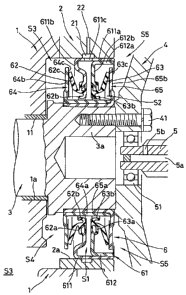
In Fig. 1, a reference code 1 is a crank case of
the wet type engine. A reference code 2 is a housing
attached to an outer periphery of an opening part of
a shaft hole la in the crank case 1. A reference code
3 is a crank shaft which is inserted into the shaft
hole la of the crank case 1 in the approximately
horizontal direction and rotatably and axially
17
CA 02572899 2007-01-04
supported by a bearing 11. A reference code 4 is a
flywheel attached to a rear end part 3a of the crank
shaft 3 by a bolt 41. A reference code 5 is a
transmission shaft having one end rotatably supported
by an inner periphery of the flywheel 4 through a
bearing 51. The crank shaft 3 corresponds to a rotary
shaft described in the first aspect. A lip type end
face sealing device 6 according to a first embodiment
of the present invention is mounted between an inner
peripheral face of the housing 2 and an outer
peripheral face of the rear end part 3a of the crank
shaft 3 which is projected from the shaft hole la of
the crank case 1.
The lip type end face sealing device 6 includes
an annular case 61 tight fitted to an inner peripheral
face 2a of the housing 2; a pair of seal lips (first
and second seal lips) 62 and 63, which are integrally
fitted to an inner periphery of the case 61; and a pair
of slingers (first and second slingers) 64 and 65,
which are attached to an outer peripheral face of the
rear end part 3a of the crank shaft 3.
As illustrated in Figs. 1 and 2, the case 61
includes a pair of case members (first and second case
members) 611 and 612, which are formed by punching and
pressing a metal plate such as a steel plate or the
18
CA 02572899 2007-01-04
like. More particularly, the first case member 611
includes a fitting cylindrical part 611a which is
pressed-in and tight fitted to the inner peripheral
face 2a of the housing 2 having a predetermined
interference; and an inner peripheral flange part 611b
which extends from one end of the fitting cylindrical
part 611a to the inner peripheral side. Further, the
second case member 612 includes a fitting cylindrical
part 612a which is pressed-in and fitted in a tight
contacting state to an inner peripheral face of the
cylindrical part 611a in the first case member 611;
and an inner peripheral flange part 612b which extends
from one end of the fitting cylindrical part 612a to
the inner peripheral side. A vent space Sl extending
in the diameter direction is formed between the inner
peripheral flange parts 611b and 612b. Further, an
air hole 611c facing the vent space S1 is provided and
opened at the inside of a fitting part where the fitting
cylindrical part 611a of the first case member 611 is
fitted with the fitting cylindrical part 612a of the
second case member 612.
The first and second seal lips 62 and 63 are made
of a rubber like elastic material. Basic parts 62a
and 63a of these seal lips 62 and 63 are integrally
vulcanization-bonded to the inner peripheral flange
19
CA 02572899 2007-01-04
parts 611b and 612b of the first and second case members
611 and 612 in the case 61, so as to cover inner
peripheral parts of the inner peripheral flange parts
611b and 612b. The first and second seal lips 62 and
63 are formed from the basic parts 62a and 63a toward
the outer peripheral side and are positioned
oppositely to each other in the axial direction so as
to be opened in a tapered shape. Further, tongue piece
parts 62b and 63b are formed on the inner peripheries
of the basic parts 62a and 63b, and are positioned
oppositely to each other in the axial direction.
The first and second slingers 64 and 65 are formed
by punching and pressing a metal plate such as a steel
plate or the like. The slingers 64 and 65 respectively
have fitting cylindrical parts 64a and 65a on inner
peripheriesthereof, andthefittingcylindricalparts
64a and 65a are pressed-in and fitted each other in
a tight contacting state, so as to be integrated.
Further, the fitting cylindrical part 65a of the
slinger 65 at the relatively inner peripheral side is
pressed-in and fitted to an outer peripheral face of
a rear end part 3a of the crank shaft 3 in a tight
contacting state with the predetermined interference.
The first slinger 64 has a flange part 64b
positioned at the axial directionally inner side (the
CA 02572899 2007-01-04
crank case 1 side) of the inner peripheral flange part
611b of the first case member 611 in the case 61. The
second slinger 65 has a flange part 65b positioned at
the axial directionally outer side (the flywheel 4
side) of the inner peripheral flange part 612b of the
second case member 612 in the case 61. Further, the
first and second seal lips 62 and 63 have end edges
62c and 63c which are positioned oppositely to each
other. The end edges 62c and 63c is tight contacted
with end faces of the flange parts 64b and 65b which
are approximately vertical with respect to the shaft
axis, while slightly bending and deforming toward the
inner flange parts 611b and 612b sides of the first
and second case members 611 and 612.
A sliding face of the flange part 64b of the first
slinger 64 to the first seal lip 62 has a plurality
of spiral grooves (for example, four spiral grooves)
64c for having a pumping work to push out a liquid
toward the outer peripheral side by rotation. Further,
a sliding face of the flange part 65b of the second
slinger 65 to the second seal lip 63 is formed to be
a flat face. However, spiral grooves which are as
symmetrical as the spiral grooves 64c of the flange
part 64b may be formed on the sliding face of the flange
part 65b, so as to have the pumping work to push out
21
CA 02572899 2007-01-04
a liquid toward the outer peripheral side at the time
of the rotation.
The first seal lip 62 is integrally
vulcanization-formed with the first case 611 by the
steps of setting the first case member 611 into a
predetermined metal mold (not illustrated in the
drawings) in which a vulcanization adhesive is coated
on the inner peripheral flange part 611b in advance;
filling a unvulcanization rubber material for molding
into an annular cavity which is defined so as to extend
from the surrounding of the inner peripheral flange
part 611b after closing the metal mold; and heating
and pressurizing it. The second seal lip 63 is also
integrally formed with the second case member by the
same steps as the first seal lip 62. Then, the fitting
cylindrical part 612a of the second case member 612
is pressed-in and fitted to the fitting cylindrical
part 611a of the first case member 611, so as to
assemble the case 61 having integrally the first and
second seal lips 62 and 63. Further, the first and
second slingers 64 and 65 are integrated by pressing-in
and fitting the fitting cylindrical parts 64a and 65a
from the axial directionally both sides of the case
61. Thereby, these parts are made into a unit as
illustrated in Fig. 2.
22
CA 02572899 2007-01-04
The inner peripheral face 2a of the housing 2
illustrated in Fig. 1 has an annular groove 21 at the
axial directional position, which corresponds to that
of the vent hole 6llc when the case 61 of the lip type
end face sealing device 6 is pressed-in, positioned,
and fixed. A vent hole 22 is opened at a part in the
circumferencial direction of the annular groove 21.
The vent space Sl, the air hole 611c, the vent groove
21 and the vent hole 22 are for constituting the vent
passage described in the first aspect. That is, in
the mounted state in Fig. 1, the seal internal spaces
S2 formed between the sliding parts of the first and
second seal lips 62 and 63 and the first and second
slingers 64 and 65 are opened to the atmosphere through
the vent space Sl, the vent hole 611c, the vent groove
21, and the vent hole 22, which are formed between the
fist case member 611 and the second case member 612
in the case 61.
In the above-described constitution, a lower part
of a crank chamber S3 in the crank case 1 has the bearing
11 and stores a proper amount of engine oil (not
illustrated in the drawings) for lubricating a piston
or the like inside the engine. On the other hand, an
internal chamber (the right side in Fig. 1) of the
housing 2 stores clutch oil (not illustrated in the
23
CA 02572899 2007-01-04
drawings) supplied to a clutch plate from an injection
open 5b through an inner peripheral hole 5a of a
transmission shaft 5. Further, the lip type end face
sealing device 6 is for sealing to prevent that the
engine oil scattered in the crank chamber S3 and the
clutch oil scattered in the housing 2 are mixed each
other through a shaft periphery of the rear end part
3a of the crank shaft 3.
More particularly, when the crank shaft 3 is
rotated, the flange parts 64b and 65b of the first and
second slingers 64 and 65 rotated together with the
crank shaft 3 are tight contacted and slid with the
end edges 62c and 63c of the first and second seal lips
62 and 63, which are fixed on the housing 2 side through
the case (the first and second case members 611 and
612) and are not rotated. Further, when the engine
oil reaching to a space S4 between the lip type end
face sealing device 6 and the crank case 1 is going
to pass the sliding part of the flange part 64b of the
fist slinger 64 and the first seal lip 62 toward the
inner peripheral side, the engine oil is discharged
toward the outer peripheral side by centrifugal force
generated by the rotation of the flange part 64b.
Similarly, when the scattered clutch oil reaching to
a space S5 between the lip type end face sealing device
24
CA 02572899 2007-01-04
6 and the flywheel 4 is going to pass the sliding part
of the flange part 65b of the second slinger 65 and
the second seal lip 63 toward the inner peripheral side,
the clutch oil is discharged toward the outer
peripheral side by centrifugal force generated by
rotation of the flange part 65b.
At this time, an oil amount of the engine oil
reaching to the space S4 from the crank chamber S3 is
much more than an oil amount of the clutch oil scattered
toward the space S5. However, at the sliding part of
the flange part 64b of the first linger 64 and the first
seal lip 6 2 , the spiral groove 64c formed on the flange
part 64b have the pumping work to remove the liquid
toward the outer peripheral side. Thus, excellent
sealability can be exercised according to the
centrifugal force by rotation of the flange part 64b.
Further, air in the seal internal space S2 in the
lip type end face sealing device 6 is discharged from
the sliding parts, by the centrifugal force and the
pumping work generated at the spiral groove 64c in the
sliding part of the flange part 64b of the first slinger
64 and the first seal lip 62, and by the centrifugal
force generated in the sliding part of the flange part
65b of the second slinger 65 and the second seal lip
63. However, the seal internal space S2 is opened to
CA 02572899 2007-01-04
the atmosphere through the vent space Sl, the vent hole
6l1c, the vent groove 21 and the vent hole 22, which
are formed between the first case member 611 and the
second case member 612 in the case 61. So, the
pressure in the space S2 does not become negative.
Therefore, entirelycontacting of the first and second
seal lips 62 and 63 to the flange parts 64b and 65b
of the first and second slingers 64 and 65 by the
negative pressure can be prevented. Further, the
first and second seal lips 62 and 63 are different from
the radial seal lip in Fig. 5 described above, and are
tight contacted with the first and second slingers 64
and 65 by bending reaction force in the axial direction.
So, the face pressures of the first and second seal
lips 62 and 63 are low. Therefore, increasing of
sliding load and early abrasions of the first and
second seal lips 62 and 63 caused from increasing of
sliding load can be effectively prevented.
In addition, in the sliding parts of the flange
parts 64b and 65b of the first and second slingers 64
and 65 and the first and second seal lips 62 and 63,
if a slight amount of the engine oil or the clutch oil
is invaded from upper half parts toward the inner
peripheral side, the leaking liquid is pushed and
returned toward the outer peripheral side by the
26
CA 02572899 2007-01-04
centrifugal force and the pumping work at the flange
parts 64b and 65b sides. However, at the upper half
parts sides of the first and second seal lips 62 and
63, the leaking liquid flows downward along the tapered
surfaces of these lips, and the tongue piece parts 62b
and 63b receives the leaking liquid. Further, the
leaking liquid flows toward a lower half part along
the circumferencial groove between the tongue piece
parts 62b and 63b and the first and second seal lips
62 and 63, and flows and falls downward, that is, to
the outer peripheral side, along the tapered surfaces
of the lower half parts of the first and second seal
lips 62 and 63. Thus, the leaking liquid is pushed
and returned to the outer peripheral side from the
sliding parts of the flange parts 64b and 65b by the
centrifugal force and the pumping work.
Fig. 3 is a half cross sectional view illustrating
the state that a lip type end face sealing device
according to a second embodiment of the present
invention is mounted, by cutting a plane passing a
shaft axis. This lip type end face sealing device is
properly applied as a sealing means between engine oil
and clutch oil in a wet type engine of a construction
machine or the like. That is, the lip type end face
sealing device 6 includes an annular case 61 tight
27
CA 02572899 2007-01-04
fitted to an inner peripheral face 2a of a housing 2,
a pair of seal lips (first and second seal lips) 62
and 63 integrally provided at an inner periphery of
the case 61, and a pair of slingers (first and second
slingers) 64 and 65 attached to a rear end part outer
peripheral face of a crank shaft not illustrated in
the drawings.
The case 61 is formed by punching and pressing
a metal plate such a steel plate or the like. The case
61 includes a fitting cylindrical part 61a pressed into
the inner peripheral face 2a of the housing 2 with a
predetermined interference and an inner peripheral
flange part 6lb extending from one end of the fitting
cylindrical part 61a toward the inner peripheral side.
The first and second seal lips 62 and 63 are made
of a rubber like elastic material. The first and
second seal lips 62 and 63 are connected each other
through a basic part 66 which is shared by the lips
62 and 63. The first and second seal lips 62 and 63
are positioned oppositely to each other in the axial
direction and opened in a tapered shape. Further, the
basic part 66 is integrally vulcanization-bonded to
the case 61. An outer peripheral part of the basic
part 66 surrounds the outer peripheral side of the
fitting cylindrical part 61a of the case 61 so as to
28
CA 02572899 2007-01-04
constitute a gasket part 66a tight contacted with the
inner peripheral face 2a of the housing 2 with a
predetermined margin.
The first and second slingers 64 and 65 are
similar to the slingers in the embodiments in Figs.
1 and 2 described above. A sliding face of a flange
part 64b of the first slinger 64 to the first seal lip
62 has a plurality of spiral grooves (for example, four
spiral grooves) 64c having a pumping work to push out
liquid toward the outer peripheral side by rotation.
Further, also in this embodiment, although a sliding
face of the flange part 65b of the second slinger 65
to the second seal lip 63 is a flat face, spiral grooves
which are symmetrical with the spiral grooves 64c of
the flange part 64b may be formed.
Further, the first and second seal lips 62 and
63 have end edges 62c and 63c which are positioned
oppositely to each other. The end edges 62c and 63c
are tight contacted with flange parts 64b and 65b of
the first and second slingers 64 and 65, which are
vertical with respect to the shaft axis. These end
edges are slightly bent and deformed to the inner
flange parts 611b and 612b sides of the first and second
case members 611 and 612.
A vent tube 67 is inserted into an inner
29
CA 02572899 2007-01-04
peripheral part of the basic part 66 of the first and
second seal lips 62 and 63. An outer peripheral face
of the vent tube 67 and the basic part 66 are tight
contacted each other. One end 67a of the vent tube
67 is opened on an inner periphery of the basic part
66, and another end 67b can be tight connected to the
vent hole 22 opened on the inner peripheral face 2a
of the housing 2. That is, in the mounting state of
the lip type end face sealing device 6, the seal
internal spaces S2 between the sliding parts of the
first and second seal lips 62 and 63 and the flange
parts 64b and 65b of the first and second slingers 64
and 65 are opened to the atmosphere through the vent
tube 67 and the vent hole 22.
In the lip type end face sealing device 6
according to the second embodiment having the
above-described structure, similarly to the first
embodiment, the case 61 is attached to the inner
peripheral face 2a of the housing 2, and the first and
second slingers 64 and 65 are attached to the outer
peripheral face of the rear end part 3a of the crank
shaft 3. Then, to prevent the engine oil scattered
in the crank chamber S3 shown in Fig. 1 and the clutch
oil scattered in the housing 2 from being mixed each
other through a shaft periphery of the rear end part
CA 02572899 2007-01-04
3a of the crank shaft 3, sealing is carried out by the
sliding parts of the first and second seal lips 62 and
63 and the flange parts 64b and 65b of the first and
second slingers 64 and 65.
Further, also in this case, the engirie oil
reaching to the sliding parts of the first seal lip
62 and the flange part 64b of the first slinger 64 is
discharged toward the outer peripheral side by the
centrifugal force by the rotation of the flange part
64b and the pumping work of the spiral groove 64c.
Further, the scattered clutch oil reaching to the
sliding parts of the second seal lip 63 and the flange
part 65b of the second slinger 65 is discharged by the
centrifugal force by the rotation of the flange part
65b.
Further, the seal internal spaces S2 between the
sliding parts of the first and second seal lips 62 and
63 and the flange parts 64b and 65b of the first and
second slingers 64 and 65 are opened to the atmosphere
through the vent tube 67 and the vent hole 22. Thus,
the pressure in the spaces S2 does not become negative
by the centrifugal force and the pumping work occurring
at the sliding parts of the flange part 64b of the first
slinger 64 and the first seal lip 62, and by the
centrifugal force occurring at the sliding parts of
31
CA 02572899 2007-01-04
the flange part 65b of the second slinger 65 and the
second seal lip 63. Therefore, entirely contacting
of the first and second seal lips 62 and 63 to the flange
parts 64b and 65b of the first and second slingers 64
and 65 by the negative pressure can be prevented.
Further, the first and second seal lips 62 and 63 are
tight contacted with the flange parts 64b and 65b by
bending reaction force in the axial direction, so that
the face pressures of the seal lips 62 and 63 are low.
Thus, increasing of sliding load and early abrasions
of the first and second seal lips 62 and 63 caused from
increasing of the sliding load can be effectively
prevented.
In both of the first embodiment illustrated in
Figs. 1 and 2 and the second embodiment illustrated
in Fig. 3, the first and second seal lips 62 and 63
are integrated, and the first and second slingers 64
and 65 are integrally fitted. However, the first
sealing lip 62 and the first slinger 64 for sealing
the engine oil, and the second seal lip 63 and the
second slinger 65 for sealing the clutch oil, may be
structured as separate members each other. Fig. 4 is
a half cross sectional view illustrating a lip type
end face sealing device according to a third embodiment
of the present invention having such the structure,
32
CA 02572899 2007-01-04
by cutting a plane passing a shaft center.
That is, the lip type end face sealing device 6
comprises a pair of end face seals 6A and 6B. The first
end face seal 6A includes an annular case 61A tight
fitted at a crank case side (the left side in Fig. 4)
on an inner peripheral face 2a of a housing 2, a seal
lip 62 integrally provided with the case 61A, and a
first slinger 64 attached at the crank case side (the
left side in Fig. 4) on a rear end outer peripheral
face of a crank shaft 3. Similarly, the second end
face seal 6B includes, an annular case 61B tight fitted
at a flywheel side (the right side in Fig. 4) on the
inner peripheral face 2a of the housing 2, a seal lip
63 integrally provided with the case 61B, and a second
slinger 65 attached at the flywheel side (the right
side in Fig. 4) on the rear end part outer peripheral
face of the crank shaft 3.
The cases 61A and 61B are formed by punching and
pressing a metal plate such a steel plate or the like.
The cases 61A and 61B include a fitting cylindrical
part 61a pressed-in and tight fitted to the inner
peripheral face 2a of the housing 2 with a
predetermined interference and an inner peripheral
flange part 61b extending from one end of the fitting
cylindrical part 61a toward the inner peripheral side.
33
CA 02572899 2007-01-04
The inner peripheral flange parts 61b are positioned
oppositely and separately to each other.
The first seal lip 62 in the first end face seal
6A is made of a rubber like elastic material. The
first seal lip 62 is opened in a tapered shape toward
the crank case side (the left side in Fig. 4) . A basic
part 62a of the first seal lip 62 is integrally
vulcanization-bonded to the case 61A. An outer
peripheral part of the basic part 62a surrounds the
outer peripheral side of the fitting cylindrical part
61a of the case 61A, so as to constitute a gasket part
62d tight contacted with the inner peripheral face 2a
of the housing 2 with a predetermined margin. Further,
an inner periphery of the basic part 62a has a tongue
piece part 62b directed to the crank case side (the
left side in Fig. 4).
The second seal lip 63 in the second end face seal
6B is similar to the first seal lip 62, and is provided
symmetrically with the first seal lip 62. That is,
the second seal lip 63 is formed so as to be opened
in a tapered shape toward the flywheel side (the right
side in Fig. 4). A basic part 63a of the second seal
lip 63 is integrally vulcanization-bonded to the case
61B. An outer peripheral part of the basic part 63a
surrounds the outer peripheral side of the fitting
34
CA 02572899 2007-01-04
cylindrical part 61a of the case 61B, so as to
constitute a gasket part 63d tight contacted with the
inner peripheral face 2a of the housing 2 with a
predetermined margin. Further, an inner periphery of
the basic part 63a has a tongue piece part 63b directed
to the flywheel side (the right side in Fig. 4).
The first slinger 64 in the first end face seal
6A is formed by punching and pressing a metal plate
such a steel plate or the like, and includes a fitting
cylindrical part 64a tight pressed-in and fitted to
the rear end part outer peripheral face of the crank
shaft 3 with a predetermined interference. An outer
peripheral end edge 62c of the first seal lip 62 is
tight contacted with the flange part 64b which is
approximately vertical to a shaft axis, while being
slightly bent and deformed to the inner peripheral
flange part 61b side of the case 61A. Further, a
sliding face of the flange part 64b of the first slinger
64 to the first seal lip 62 has a plurality of spiral
grooves (for example, four spiral grooves) 64c having
a pumping work to push out liquid toward the outer
peripheral side by rotation.
On the other hand, the second slinger 65 in the
second end face seal 6B is similar to the first slinger
64, and is formed by punching and pressing a metal plate
CA 02572899 2007-01-04
such a steel plate or the like. Further, the slinger
65 includes a fitting cylindrical part 65a tight
pressed-in and fitted to the rear end part outer
peripheral face of the crank shaft 3 with a
predetermined interference, and is provided
symmetrically with the first slinger 64. An outer
peripheral end edge 63c of the second seal lip 63 is
tight contacted with the flange part 65b which is
approximately vertical to a shaft axis, while slightly
bent and deformed to the inner peripheral flange part
6lb side of the case 61B. Further, although a sliding
face of the flange part 65b of the second slinger 65
with the second seal lip 63 is formed to be a flat,
spiral grooves which are symmetrical with the spiral
grooves 64c of the first slinger 64 may be formed.
The inner peripheral face 2a of the housing 2 has
a vent hole 22 opened and positioned between a mounting
position of the case 61A in the first end face seal
6A and a mounting position of the case 6lB in the second
end face seal 6B. That is, when the first end face
seal 6A and the second end face seal 6B are mounted,
the seal internal spaces S2 between the sliding parts
of the first and second seal lips 62 and 63, and the
first and the second slingers 64 and 65 are opened to
atmosphere through the vent hole 22.
36
CA 02572899 2007-01-04
Therefore, also in the lip type end face sealing
device 6 according to the third embodiment, the effects
similar to those in the first and second embodiments
described above can be obtained. That is, since the
seal internal space S2 defined between the first end
face seal 6A and the second end face seal 6B is opened
to atmosphere through the vent hole 22, the pressure
in the space S2 does not become negative, by the
centrifugal force and pumping work occurring at the
sliding parts of the flange part 64b of the first
slinger 64 and the first seal lip 62, and by the
centrifugal force occurring at the sliding parts of
the flange part 65b of the second slinger 65 and the
second seal lip 63. Thus, increasing of sliding load
and early abrasions of the first and second seal lips
62 and 63 caused by increasing of sliding load can be
effectively prevented. Further, the tongue piece
parts 62b and 63b have functions similar to those in
the first embodiment described above.
Fig. 5 is a half cross sectional view illustrating
a lip type end face sealing device according to a fourth
embodiment of the present invention by cutting a plane
passing a shaft axis. This lip type end face sealing
device is applied as a sealing means between engine
oil and atmosphere in an engine having severe external
37
CA 02572899 2007-01-04
dust conditions, such as an engine of a construction
machine or the like. That is, the lip type end face
sealing device 6, similarly to that of the second
embodiment (Fig. 3) described above, includes an
annular case 61 pressed into an inner peripheral face
2a of a housing 2 at a fitting cylindrical part 61a,
a pair of seal lips (first and second seal lips) 62
and 63 integrally provided at an inner periphery of
the case 61, and a pair of slingers (first and second
slingers) 64 and 65 attached to a rear end part outer
peripheral face of a crank shaft 3. The first seal
lip 62 is for sealing engine oil at the left side in
Fig. 5 and the second seal lip 63 is for sealing dusts
in the atmosphere at the left side in Fig. 5
Difference from the second embodiment is
described concretely as follows. The first slinger
64 is tight pressed-in and fitted to an outer
peripheral face of a rear end part 3a of the crank shaft
3 with a predetermined interference at a fitting
cylindrical part 64a. The first slinger is tight
contacted with an end edge 62c of the first seal lip
62 at a flange part 64b which is approximate vertical
to a shaft axis. On the other hand, the second slinger
65 has a holding cylindrical part 65c extending from
a fitting cylindrical part 65a toward the axial
38
CA 02572899 2007-01-04
directional external side (the left side in Fig. 5)
The fitting cylindrical part 65a is pressed-in and
fitted to an outer peripheral face of a fitting
cylindrical part 64a of the first slinger 64, at the
crank case side (the right side in Fig. 5) with a
predetermined interference. The flange part 65b
which is approximately vertical to a shaft axis is
extended from an end part of the holding cylindrical
part 65c.
The first and second slingers 64 and 65
respectively have a plurality of spiral grooves (for
example, four grooves) 64c and 65d, and the spiral
grooves 64c and 65d have a pumping function to push
out liquid at the outer peripheral side by rotation,
and are symmetrically formed each other. Further, a
grease (not illustrated in the drawings) for
lubricating is filled to the sliding parts of the
flange part 65b of the second slinger 65 at atmosphere
side and the second seal lip 63.
An inner peripheral face of the holding
cylindrical part 65c in the second slinger 65 has a
larger diameter than that of an outer peripheral face
of the fitting cylindrical part 64a of the first
slinger 64. That is, a vent space S6 is formed between
the holding cylindrical part 65c of the second slinger
39
CA 02572899 2007-01-04
65 and fitting cylindrical part 64a of the first
slinger 64. Further an air hole 65e is opened at a
position at the fitting cylindrical part 65a side of
the holding cylindrical part 65c. The air hole 65e
and the vent space S6 constitute a vent passage,
through which the seal internal spaces S2 formed
between the sliding parts of the first and second seal
lips 62 and 63 and the first and second slingers 64
and 65 is opened to the atmosphere side (the right side
in Fig. 5).
The vent space S6 is filled with a dust filter
68, and is caulked by a caulked part 64d formed at an
end of the fitting cylindrical part 64a of the first
slinger 64. The dust filter 68 is made of a fiber
aggregate such as a synthetic fabric and cotton, and
has permeability due to fine spaces among fibers.
In the lip type end face sealing device 6
according to the fourth embodiment having the
constitution mentioned above, the case 61 is attached
to the inner peripheral face 2a of the housing 2, and
the first and second slingers 64 and 65 are attached
to the outer peripheral face of the rear end part 3a
of the crank shaft 3. Thereby, leakage of engine oil
in the crank chamber of the engine from the sliding
parts of the first seal lip 62 and the flange part 64b
CA 02572899 2007-01-04
of the first slinger 64 can be prevented. Further,
invasion of dusts in the atmosphere into the crank
chamber of the engine from the sliding parts of the
second seal lip 63 and the flange part 65b of the second
slinger 65 can be prevented. Furthermore, a part
between the inner peripheral face 2a of the housing
2 and the fitting cylindrical part 61a of the case 61
is sealed by the gasket part 66a extending from the
basic part 66, which is shared by the first and second
seal lips 62 and 63.
Further, as for the sliding parts of the flange
parts 64b and 65b of the first and second slinqers 64
and 65 and the first and second seal lips 62 and 63,
the spiral grooves 64c and 64d formed at the flange
parts 64b and 65b have the pumping work to discharge
liquid toward the outer peripheral side by rotation.
Thus, excellent sealability can be exercised according
to the centrifugal force by rotations of the flange
parts 64b and 65b. In addition, the tongue piece part
62b has functions similar to that of the first
embodiment described above.
Further, the air in the seal internal spaces S2
in the lip type end face sealing device 6 is discharged
to the outer peripheral side from the sliding parts
of the flange parts 64b and 65b and the first and second
41
CA 02572899 2007-01-04
seal lips 62 and 63, by the pumping work and the
centrifugal force. Thus, air outside the device is
sucked into the seal internal spaces S2 through the
dust filter 68 and the air hole 65e in the vent space
S6. Therefore, entirely contacting of the first and
second seal lips 62 and 63 to the flange parts 64b and
65b of the first and second slingers 64 and 65 by
negative pressure can be prevented. Further, since
the first and second seal lips 62 and 63 are tight
contacted with the first and second slingers 64 and
65 by bending reaction force in the axial direction,
the face pressures of the seal lips 62 and 63 are low.
Thus, increasing of sliding load and early abrasions
of the first and second seal lips 62 and 63 caused
thereby can be effectively prevented.
Further, the dusts contained in atmosphere
outside the device, which are sucked into the seal
internal spaces S2 through the vent space S6 and the
air hole 65e, are separated by the dust filter 68 filled
in the vent space S6. Thus, clean air is sucked into
the seal internal spaces S2. Therefore, invasion of
the dusts into the engine oil in the crank chamber from
the sliding parts of the flange part 64b of the first
slinger 64 and the first seal lip 62 can be prevented.
Further, according to the above-described
42
CA 02572899 2007-01-04
constitution, the dust filter 68 is not abraded by
sliding, unlike a filter put between a stationary side
and a rotation side. Further, there is no generation
of a space by eccentricity of the housing 2 and the
crank shaft 3. Further, like the embodiment in the
drawing, the dust filter 68 is formed in a cylindrical
shape, and the air hole 65e is formed at the end part
of the dust filter 68. Thus, the filtrating route of
air is lengthened, so that excellent removability to
dusts can be obtained. Furthermore, according to this
embodiment, the vent passage including the vent space
S6 and the air hole 65e is formed only in the lip type
end face sealing device 6, so that a vent hole does
not need to be formed at the housing 2.
Figs. 6 and 7 are half cross sectional views
illustrating an example that a shape of the lip type
end face sealing device according to the fourth
embodiment illustrated in Fig. 5 is varied, by cutting
a plane passing a shaft axis.
The lip type end face sealing device 6 illustrated
in Fig. 6 is basically similar to that in Fig. S. The
device 6 includes an annular case 61 pressed into an
inner peripheral face 2a of a housing 2, first and
second seal lips 62 and 63 integrally provided on an
inner periphery of the case 61, and first and second
43
CA 02572899 2007-01-04
slingers 64 and 65 attached at a crank shaft 3 side.
The first seal lip 62 is for sealing engine oil at the
left side in Fig. 6, and the second seal lip 63 is for
sealing dusts in atmosphere at the right side in Fig.
6.
Difference from the embodiment in Fig. 5 is
described concretely as follows. An annular holder
69 is pressed-in and fitted to an outer peripheral face
of a fitting cylindrical part 64a of the first slinger
64. A fitting cylindrical part 65a of the second
slinger 65 is pressed-in and fitted to an outer
peripheral face of a fitting cylindrical part 69a in
the annular holder 69. The annular holder 69 is formed
by punching and pressing a metal plate such as a steel
plate or the like. The annular holder 69 includes a
flange part 69b which is approximately vertical to a
shaft axis like the second slinger 65. A vent space
S7 is formed between the flange part 69b and the flange
part 65b of the second slinger 65. Further, an air
hole 65e is opened at a position of an inner periphery
side in the flange part 65b of the second slinger 65.
The air hole 65e and the vent space S7 constitute a
vent passage, through which the seal internal spaces
S2 between the sliding parts of the first and second
seal lips 62 and 63 and the first and second slingers
44
CA 02572899 2007-01-04
64 and 65 is opened to the atmosphere side (the right
side in Fig. 6).
The vent space S7 is filled with a dust filter
68. The dust filter 68 has an annular shape which is
flat in the axial direction, that is, has a disc shape.
Further, the dust filter 68 is made of a fiber aggregate
such as a synthetic fabric and cotton, and has
permeability due to fine spaces among fibers, like that
of the embodiment in Fig. 5.
The lip type end face sealing device 6 in Fig.
6 having the above-described structure basically has
functions similar to the embodiment in Fig. S. That
is, air in the seal internal spaces S2 is discharged
from the sliding part of the flange parts 64b and 65b
of the first and second slingers 64 and 65 and the first
and second seal lips 62 and 63 at the time of rotating.
According to discharging of the air, air outside the
device is sucked through the vent space S7 between the
flange part 69b of the annular holder 69 and the flange
part 65b of the second slinger 65 and the air hole 65e.
Thus, generation of the negative pressure in the seal
internal spaces S2 can be prevented, and dusts
contained in the sucked air outside the device can be
removed by the dust filter 68 filled in the vent space
S7.
CA 02572899 2007-01-04
Further, according to this embodiment, the dust
filter 68 is formed in the disc shape. So, when the
air hole 65e is opened in the flange part 65b of the
second slinger 65 so as to be positioned at an inner
peripheral part of the dust filter 68, the filtrating
route of the air is lengthened, so that excellent
removability to the dusts can be obtained. Further,
a vent hole or the like is unnecessary to be formed
at the housing 2, like the embodiment in Fig. 5.
Furthermore, according to this embodiment, the dust
filter 68 is held between the flange parts 65b and 69b,
so that the dust filter 68 is not moved from the exact
position, and is not damaged when assembling.
On the other hand, the lip type end face sealing
device 6 illustrated in Fig. 7 basically has a similar
structure to the embodiment of Fig. 5. A first seal
lip 62 is for sealing engine oil at the left side in
Fig. 7, and a second seal lip 63 is for sealing dusts
in atmosphere at the right side in Fig. 7.
Difference from the embodiments in Fig. 5 and 6
is described concretely as follows. A fitting
cylindrical part 65a of a second slinger 65 is
pressed-in and fitted to an outer peripheral face of
a fitting cylindrical part 64a of a first slinger 64.
An air hole 65e is opened in an inner peripheral part
46
CA 02572899 2007-01-04
of a flange part 65b in the second slinger 65. Further,
an annular dust filter 68 is added to an inner face
of the inner peripheral part of the flange part 65b
so as to close the air hole 65e. The dust filter 68
is also made of a fiber aggregate such as a synthetic
fabric and cotton, and has permeability due to fine
spaces among fibers. The dust filter 68 is fixed by
a proper adhesive agent.
The lip type end face sealing device 6 in Fig.
7 having the above-described constitution basically
has similar functions to those of the embodiment in
Fig. 5. Further, air in the seal internal spaces S2
is discharged from the sliding part of the flange parts
64b and 65b of the first and second slingers 64 and
65 and the first and second seal lips 62 and 63 at the
time of rotating by centrifugal force or pumping work
of spiral grooves 64c and 65d. According to
discharging of the air, air outside the device is
sucked through the air hole 65e opened in the flange
part 65b of the second slinger 65. Thus, generation
of the negative pressure in the seal internal spaces
S2 can be prevented, and dusts contained in the sucked
air outside the device can be removed by the dust filter
68 provided at the air hole 65e.
Further, according to this embodiment, the vent
47
CA 02572899 2007-01-04
passage for releasing the pressure in the seal internal
spaces S2 toward the atmosphere side is constituted
by only the air hole 65e opened in the flange part 65b
of the second slinger 65. Further, the dust filter
68 is only adhered to the flange part 65b of the second
slinger 65. So, the number of parts can be decreased,
and the structure can be simplified.
Fig. 8 is a half cross sectional view illustrating
a lip type end face sealing device according to a fifth
embodiment of the present invention, by cutting a plane
passing a shaft axis, where the lip type end face
sealing device is properly applied as a sealing means
between engine oil and atmosphere in an engine having
severe external dust conditions.
The lip type end face sealing device 6 comprises
an end face seal 6C and a dust cover 6D. The end face
seal 6C includes an annular case 61 pressed into an
inner peripheral face 2a of a housing 2 at a fitting
cylindrical part 61a, a seal lip 62 integrally provided
on an inner periphery of the case 61, a slinger 64
attached to an outer peripheral face of a crank shaft
3, and a first dust filter 68A.
The case 61 in the end face seal 6C is formed by
punching and pressing a metal plate such as a steel
plate or the like. The case 61 includes the fitting
48
CA 02572899 2007-01-04
cylindrical part 61a pressed-in and tight fitted to
the inner peripheral face 2a of the housing 2 with a
predetermined interference, an outer peripheral
flange part 6lc extending from one end of the fitting
cylindrical part 61a toward the inner peripheral side,
and an inner peripheral flange part 61b extending from
an inner periphery of the outer peripheral flange part
6lc toward the inner peripheral side through an
intermediate part 61d extending toward the crank case
side (the left side in Fig. 8).
The seal lip 62 in the end seal 6C is made of a
rubber like elastic material, and is opened in a
tapered shape toward the crank case side (the left side
in Fig. 8). A basic part 62a of the seal lip 62 is
integrally vulcanization-bonded to the case 61. An
outer peripheral part of the basic part 62a surrounds
the outer peripheral side of the fitting cylindrical
part 61a of the case 61, so as to constitute a gasket
part 62d tight contacted with the inner peripheral face
2a of the housing 2 with a predetermined margin.
Further, the inner periphery of the basic part 62a has
a tongue piece part 62b directed to the crank case side.
Furthermore, the end face of the outer peripheral
flange part 61c of the case 61 directed to the
atmosphere side is exposed from a rubber layer
49
CA 02572899 2007-01-04
extending from the basic part 62a of the seal lip 62.
The slinger 64 in the end face seal 6C is formed
by punching and pressing a metal plate such as a steel
plate or the like. The slinger 64 includes the fitting
cylindrical part 64a tight pressed-in and fitted to
an outer peripheral face of the crank shaft 3 with a
predetermined interference. Further, an outer
peripheral end edge 62c of the seal. lip 62 is slidably
tight contacted with a flange part 64b which is
approximate vertical to a shaft axis, while the seal
lip 62 is bent and deformed so as to be slightly opened.
Further, a sliding face of the flange part 64b of the
slinger 64 to the seal lip 62 may have a plurality of
spiral grooves having pumping work to push out liquid
toward the outer peripheral side by rotation.
The first dust filter 68A is attached to the inner
peripheral part of the end face seal 6C while
positioning at the atmosphere side of the tongue piece
part 62b. The first dust filter 68A is made of a fiber
aggregate such as a synthetic fabric and cotton, and
has permeability due to fine spaces among fibers.
Further, an inner peripheral part of the first dust
filter 68A is slidably contacted with the outer
peripheral face of the fitting cylindrical part 64a
of the slinger 64.
CA 02572899 2007-01-04
The dust cover 6D comprises a dust lip 70 made
of a rubber like elastic material, a reinforcement ring
71 which is formed by punching and pressing a metal
plate such as a steel plate or the like and embedded
in an inner peripheral basic part 70c of the dust lip
70, and a second dust filter 68B. As for the dust lip
70, a lip main body part 70a is formed so as to be opened
in a tapered shape toward the crank case side (the left
side in Fig. 8), and a top end face 70b is slidably
tight contacted with an end face of the outer
peripheral flange part 6lc of the case 61 in the end
face seal 6C, while being properly bent and deformed.
Further, the inner peripheral basic part 70c is tight
fitted to the outer peripheral face of the crank shaft
3 while positioning at the atmosphere side of the
slinger 64.
An air hole 70d is opened between the lip main
body part 70a and the inner peripheral basic part 70c
in the dust cover 6D (the dust lip 70) . The air hole
70d is formed at one part or plural parts in the
circumferencial direction of the dust cover 6D. The
air hole 70d passes through a rubber layer of the inner
peripheral part of the dust lip 70 and the
reinforcement ring 71 embedded in the dust lip 70. The
air hole 70d is for releasing pressures in the seal
51
CA 02572899 2007-01-04
internal spaces S2 and S8 between a sliding part of
the seal lip 62 in the end face seal 6C and a sliding
part of the dust lip 70 in the dust cover 6D, toward
the atmosphere side. The air hole 70d corresponds to
the vent passage described the sixth aspect of the
invention and is formed at one part or plural parts
in the circumferencial direction of the dust cover 6D.
The second dust filter 68B is made of a fiber
aggregate such as a synthetic fabric and cotton, and
has permeability due tofine spaces among fibers. The
second dust filter 68B is formed in annular shape, and
is fixed by an adhesive agent or the like, so as to
close the air hole 70d at the inner peripheral side
of the dust lip 70.
Therefore, according to the above-described
structure, the end face seal 6C is to prevent leakage
of engine oil in the crank chamber of an engine toward
the external of the device through the sliding parts
of the seal lip 62 and the flange part 64b of the slinger
64. The dust cover 6D is to prevent to invasion of
dusts in the atmosphere into the crank chamber of an
engine through the sliding parts of the outer
peripheral flange part 6lc of the case 61 in the end
face seal 6C and the dust lip 70. In addition, the
tongue piece part 62b has functions similar to those
52
CA 02572899 2007-01-04
of the first embodiment described above.
Further, air in the seal internal space S2 of the
end face seal 6C is discharged from the sliding parts
of the flange part 64b of the slinger 64 and the seal
lip 62 toward the outer peripheral side, by centrifugal
force occurring at the sliding parts by rotation or
by the pumping work of the spiral groove. Further,
air in the seal internal space S8 between the end face
seal 6C and the dust cover 6D is discharged toward the
outer peripheral side by centrifugal force occurring
at the sliding part of the dust lip 70 by rotation.
However, according to such the air discharging
operation, air outside of the device is sucked into
the seal internal space S8 through the air hole 70d
and the second dust filter 68B. Further, a part of
the air sucked into the seal internal space S8 is sucked
into the seal internal space S2 of the end face seal
6C through the first dust filter 68A.
Therefore, entirely contacting of the seal lip
62 and the dust lip 70 to the flange part 64b of the
slinger 64 and the outer peripheral flange part 6lc
of the case 61 by the negative pressure can be prevented.
Further, since the seal lip 62 and the dust lip 70 have
tight contacting force by only bending reaction force
in the axial direction, the face pressures are low.
53
CA 02572899 2007-01-04
Thus, increasing of sliding load, and early abrasions
of the seal lip 62 and the dust lip 70 caused by the
increasing of sliding load can be effectively
prevented. Further, according to this embodiment,
the vent passage is consisted of only the air hole 70d
of the dust cover 6D, so that the vent hole or the like
is unnecessary to be formed at the housing 2.
Further, dusts in the atmosphere outside of the
device, which are sucked into the seal internal spaces
S8 and S2, are separated by the second dust filter 68B
and the first dust filter 68A during the sucking
process. Thus, clean air is sucked into the seal
internal spaces S8 and S2. Therefore, invasion of
dusts into engine oil in the crank chamber through the
sliding parts of the flange part of the slinger 64 and
the seal lip 62 can be prevented.
The f irst dust filter 68A is abraded with passage
of time by sliding with the fitting cylindrical part
64a of the rotating slinger 64. However, the second
dust filter 68B is not abraded because of being not
slid. Therefore, excellent dust removability can be
kept.
Fig. 9 is a half cross sectional view illustrating
an example that a shape of the lip type end face sealing
device according to the fifth embodiment illustrated
54
CA 02572899 2007-01-04
in Fig. 8 is varied, by cutting a plane passing a shaft
axis. Fig. 10 is a view seen is the X direction in
Fig. 9.
In the lip type end face sealing device 6, an air
hole 70d of a dust cover 6D is formed in a slit shape
as illustrated in Fig. 10, and other portions are
similarly constituted as those of Fig. 8. More
particularly, as for a rubber layer forming a dust lip
70, a part for covering the atmosphere side of a
reinforcement ring 71 is formed to be a comparatively
thin film. As for the air hole 70d, although an
internal air hole 70d1 passing through the
reinforcement ring 71 embedded in the dust cover 6D
is formed, for example, in a circular hole shape as
illustrated with short dashed lines in Fig. 10, an
external air hole 70d2 passing through a film shaped
rubber layer 70e at the atmosphere side is formed in
a slit shape.
According to this embodiment, in the air hole 70d
of the dust cover 6D, the external air hole 70dz formed
at the rubber layer 70e is ordinary closed because of
being formed in a slit shape. The external air hole
70d2 is operated to be slightly opened when the rubber
layer is deformed by the pressure difference between
the internal space side and the atmosphere side, which
CA 02572899 2007-01-04
is generated when the pressures in the seal internal
spaces S8 and S2 becomes negative. That is, the second
dust filter 68B positioned at the inner side of the
air hole 70d is not always exposed to external dusts,
and invasion of dusts having large particles can be
prevented. Therefore, in addition to effects by the
embodiment illustrated in Fig. 8, the effects that dust
removability can be increased more and the second dust
filter 68B is hardly clogged, can be obtained.
Fig. 11 is a half cross sectional view
illustrating another example that a shape of the lip
type end face sealing device according to the fifth
embodiment illustrated in Fig. 8 is varied, by cutting
a plane passing a shaft axis.
As for this lip type end face sealing device 6,
an inner peripheral basic part 70c of a dust lip 70
in a dust cover 6D is directed to the fitting
cylindrical part 64a side of a slinger 64 in an end
face seal 6C, and other portions are similarly
constituted as those of Fig. 8. The inner peripheral
basic part 70c corresponds to the inner peripheral part
of the dust cover described in the ninth aspect of the
invention.
More particularly, the inner peripheral basic
part 70c of the dust lip 70 is tight fitted to an outer
56
CA 02572899 2007-01-04
peripheral face of a crank shaft 3, and is extended
in a cylindrical shape toward the fitting cylindrical
part 64a together with an inner peripheral cylindrical
part 71a of a reinforcement ring 71 embedded in the
dust lip 70. When a top end part of the inner
peripheral basic part 70c is contacted with an end part
of the fitting cylindrical part 64a, a top end face
70b of a lip main body part 70a of the dust lip 70 is
tight contacted with an end face of an outer peripheral
flange part 61c of a case 61 in an end face seal 6C
with proper face pressure. Further, as for the end
face seal 6C, when the device is not mounted, the case
61 (the seal lip 62) and slinger 64 are relatively
positioned in the axial direction by a proper auxiliary
metal fitting (not illustrated in the drawings) which
is detachable.
Further, an outer peripheral face of the inner
peripheral basic part 70c of the dust lip 70 has a
fitting groove 70f, and an inner peripheral part of
a second dust filter 68B is fitted to the fitting groove
70f. That is, the second dust filter 68B is fitted
to the fitting groove 70f, so as to be attached to an
inner side of an air hole 70d without using an adhesive
agent.
Therefore, according to this embodiment, when
57
CA 02572899 2007-01-04
mounting the dust cover 6D on an outer peripheral face
of a crank shaft 3, a top end part of the inner
peripheral basic part 70c of the dust lip 70 in the
dust cover 6D is contacted with the fitting cylindrical
part 64a of the slinger 64. Thereby, the dust cover
6D can be easily positioned so as to make the top end
face 70b of the dust lip 70 to be tight contacted with
the outer peripheral flange part 61c of the case 6lwith
the proper face pressure.
Further, also in the embodiment illustrated in
Fig. 11, the air hole 70d can be similarly constituted
as the embodiment in Figs. 9 and 10.
Fig. 12 is a half cross sectional view
illustrating another example that a shape of the lip
type end face sealing device according to the fifth
embodiment illustrated in Fig. 8 is varied, by cutting
a plane passing a shaft axis. Fig. 13 is a half cross
sectional view illustrating a dust cover in Fig. 12
by cutting a plane crossing a shaft axis.
In the lip type end face sealing device 6, the
air hole 70d is spirally extended along a fitting part
of an inner peripheral basic part 70c of a dust cover
6D to a crank shaft 3, and other portions are basically
constituted similarly to those in Fig. 8.
More particularly, as illustrated in Fig. 13, the
58
CA 02572899 2007-01-04
dust cover 6D has grooves (hereinafter, it is said to
as spiral grooves) on an inner peripheral face of the
inner peripheral basic part 70c tight fitted to an
outer peripheral face of the crank shaft 3, where the
grooves are spirally continued between an end part at
the atmosphere side and an end part at the seal internal
space S8 side. The spiral grooves 72 are filled with
a second dust filter 68B. The second dust filter 68B
is made of a fiber aggregate such as a synthetic fabric
and cotton or a felt, and has permeability due to fine
spaces amongfibers. Further, the second dust filter
68B is fixed with an adhesive agent or the like.
The end face seal 6C has the same structure as
that in Fig. 8, and is to prevent leakage of engine
oil in a crank chamber of an engine toward the outside
of the device through sliding parts of a seal lip 62
and a flange part 64b of a slinger 64. Air in the seal
internal space S2 of the end face seal 6C is discharged
from the sliding parts of the flange part 64b of the
slinger 64 and the seal lip 62 toward the outer
peripheral side, by centrifugal force occurring at the
sliding parts by rotation and pumping work of the
spiral grooves formed at the sliding parts. Further,
air in the seal internal space S8 between the end face
seal 6C and the dust cover 6D is discharged toward the
59
CA 02572899 2007-01-04
outer peripheral side by centrifugal force occurring
at the sliding part of the dust lip 70 by rotation.
Further, according to such the air discharge operation,
air outside the device is sucked into the seal internal
space S8 through an air hole 70d including the spiral
grooves 72 and the second dust filter 68B filled in
the spiral grooves 72. Furthermore, a part of the air
sucked into the seal internal space S8 is sucked into
the seal internal space S2 of the end face seal 6C
through the first dust filter 68A.
Therefore, entirely contacting of the seal lip
62 and the dust lip 70 to the flange part 64b of the
slinger 64 and the outer peripheral flange part 61c
of the case 61 by negative pressure can be prevented,
and increasing of sliding load and early abrasions of
the seal lip 62 and the dust lip 70 caused by the
increasing of sliding load can be effectively
prevented.
Further, dusts in the atmosphere outside of the
device, which are sucked into the seal internal spaces
S8 and S2, are separated by the second dust filter 68B
and the first dust filter 68A during the sucking
process. In addition, the air hole 70d formed at the
inner peripheral basic part 70c of the dust cover 6D
and the second dust filter 68B filled in the air hole
CA 02572899 2007-01-04
70d are spirally extended long, so that dust removing
effect is increased. Thus, only clean air is sucked
into the seal internal spaces S8 and S2. Therefore,
invasion of dusts into engine oil in the crank chamber
through the sliding parts of the flange part of the
slinger 64 and the seal lip 62 can be prevented.
In addition, the second dust filter 68B is
properly compressed by an interference of the inner
peripheral basic part 70c of the dust cover 6D with
respect to the crank shaft 3, so that the density of
the fibers may be somewhat rough.
Fig. 14 is a half cross sectional view
illustrating a lip type end face sealing device
according to a sixth embodiment of the present
invention, by cutting a plane passing a shaft axis,
where the lip type end face sealing device is applied
as a sealing means between engine oil in an engine and
atmosphere under severe external dust conditions. An
end face seal 6C is similarly constituted to that of
Fig. 8.
A dust cover 6D is similar to the seal lip 62 in
the end face seal 6C, and made of a rubber like elastic
material in an annular shape. An inner peripheral
face of a thick basic part 70c of the dust cover 6D
is tight fitted to an outer peripheral face of a crank
61
CA 02572899 2007-01-04
shaft 3 at the atmosphere side from a fitting
cylindrical part 64a in a slinger 64. Further, a top
end face 70b of a dust lip 70 opened toward the end
face seal 6C side in a tapered shape is slidably tight
contacted with an end face of an outer peripheral
flange part 61c of a case 61 in the end face seal 6C.
Centrifugal force by rotation applied to the dust
cover 6D rotated with the crank shaft 3 so as to deform
the dust lip 70 to enlarge a diameter thereof. Further,
rigidity and mass of the dust lip 70 is set so as to
separate the top end face 70b of the dust lip 70, which
the dust lip is deformed to have the enlarged diameter
by increasing of centrifugal force, from the end face
of the outer peripheral flange part 61c of the case
61 in the end face seal 6C when the rotation reaches
a predetermined rotation rate or more. This state is
illustrated with dashed lines in Fig. 14.
According to the above-described structure, the
end face seal 6C is to prevent leakage of engine oil
in a crank chamber of an engine toward the outside of
the device through sliding parts of the seal lip 62
and a flange part 64b of the slinger 64, like the
embodiment of Fig. 8. In this case, at the low
rotation rate, the centrifugal force, which is applied
so as to deform to enlarge the diameter of the dust
62
CA 02572899 2007-01-04
lip 70 of the dust cover 6D rotated with the crank shaft
3, is small and centrifugal force applied to air in
seal internal spaces S2 and S8 is small. Therefore,
large air discharging force to push and open the seal
lip 62 and the dust lip 70 does not occur, so that the
pressures in seal internal spaces S2 and S8 become
hardly negative. Further, the dust lip 70 is slidably
tight contacted with the end face of the outer
peripheral flange part 61c of the case 61 in the end
face seal 6C, so as to prevent invasion of dusts from
the atmosphere side.
Further, when the rotation rate of the crank shaft
3 is increased from this state, the air discharging
force at the sliding parts of the seal lip 62 and the
flange part 64b of the slinger 64 is increased by the
centrifugal force applied to air, or by pumping work
of spiral grooves formed at the sliding parts. The
centrifugal force applied to the dust lip 70 of the
dust cover 6D rotated with the crank shaft 3 is also
increased. Thus, the dust lip 70 is deformed as
illustrated with dashed lines in Fig. 14, and the top
end face 70b is slightly separated from the end face
of the outer peripheral flange part 6lc of the case
61 in the end face seal 6C, so that the pressures in
the seal internal spaces S2 and S8 are prevented to
63
CA 02572899 2007-01-04
become negative. Therefore, entirely contacting of
the seal lip 62 and the dust lip 70 to the flange part
64b of the slinger 64 and the outer peripheral flange
part 6lc of the case 61 by the negative pressure can
be prevented. So, increasing of sliding load and
early abrasions of the seal lip 62 and the dust lip
70 caused by the increasinq of sliding load can be
effectively prevented.
Further, in this state, air outside the device
is sucked into the seal internal space S8 through a
slight space formed between the top end face 70b of
the dust lip 70 and the outer peripheral flange part
61c of the case 61, and is sucked into the seal internal
space S2 of the end face seal 6C. However, dusts
contained in the air are separated by a dust filter
68. Therefore, only clean air is sucked into the seal
internal space S2, so that invasion of dusts into
engine oil in the crank chamber through the sliding
parts of the flange part 64b of the slinger 64 and the
seal lip 62 can be prevented.
In addition, in order to certainly generate the
above-described operation for the dust lip 70, for
example, it is considered to employ means that
weights for increasing diameter enlarging force by
centrifugal force are embedded in the outer peripheral
64
CA 02572899 2007-01-04
part of the dust lip 70 at equal intervals in the
circumferencial direction, or that thin parts for
easily enlarging the diameter of the dust lip 70 are
formed at the dust lip 70 at predetermined intervals
in the circumferencial direction.
Fig. 15 is a half cross sectional view
illustrating a lip type end face sealing device
according to a seventh embodiment of the present
invention, by cutting a plane passing a shaft axis,
where the lip type end face sealing device is applied
as a sealing means between engine oil and atmosphere
in an engine under severe external dust conditions.
An end face seal 6C is constituted similarly to that
of Fig. 8.
A dust cover 6D is basically similar to that in
Fig. 14. An inner peripheral face of a thick basic
part 70c is positioned at the atmosphere side from a
fitting cylindrical part 64a in a slinger 64, and is
tight fitted to an outer peripheral face of a crank
shaft 3. A top end face 70b of a dust lip 70 opened
toward the end face seal 6C side in a tapered shape
is slidably tight contacted with an end face of an outer
peripheral flange part 61c of the case 61 in the end
face seal 6C. Further, the dust lip 70 is thicker than
that in Fig. 14 described above. Therefore, sliding
CA 02572899 2007-01-04
width of an end face 61e of the outer peripheral flange
part 61c of the case 61 in the end face seal 6C, that
is, a diameter directional width of the top end face
70b of the dust lip 70 is comparatively large.
Any one or both of the end face 61e of the outer
peripheral flange part 61c of the case 61 in the end
face seal 6C and the top end face 70b of the dust lip
70 slidably contacted with the end face 6le are
processed with a surface roughening treatment by
embossing. Therefore, countless fine
labyrinth-shapedventpassages (not illustrated in the
drawings) are formed between the end face 61e and the
top end face 70b contacted each other.
According to the above-described structure, the
end face seal 6C is to prevent leakage of engine oil
in a crank chamber of an engine toward the outside of
the device through sliding parts of the seal lip 62
and a flange part 64b of the slinger 64, like the
embodiment of Fig. B. Further, air in a seal internal
space S2 is discharged toward the outer peripheral side
from the sliding parts of the flange part 64b of the
slinger 64 and the seal lip 62, by centrifugal force
working at the sliding parts by rotation, or by pumping
work of spiral grooves formed at the sliding parts.
However, the seal internal space S2 is opened to the
66
CA 02572899 2007-01-04
atmosphere side through a dust filter 68, the seal
internal space S8 at the inner side of the dust cover
6D, and the countless labyrinth-shaped vent passages,
which is formed by the surface roughening treatment
at the sliding parts of the end face 60e of the outer
peripheral flange part 61c of the case 61 and the top
end face 70b of the dust lip 70. Thus, the remarkably
negative pressure is not generated in the seal internal
spaces S2 and S8 by the air discharging operation.
Therefore, entirely contacting of the seal lip 62 and
the dust lip 70 to the flange part 64b of the slinger
64 and the outer peripheral flange part 6lc of the case
61 by the negative pressure can be prevented. So,
increasing of sliding load and early abrasions of the
seal lip 62 and the dust lip 70 caused by the increasing
of sliding load can be effectively prevented.
Further, according to the above-described air
discharging operation, air outside the device is
sucked into the seal internal space S8 at the inner
side of the dust cover 6D through the countless
labyrinth-shaped vent passages at the sliding parts
of the end face 61e of the outer peripheral flange part
61c of the case 61 and the top end face 70b of the dust
lip 70. In this case, the vent passages are formed
by the embossing treatment to be fine, and are formed
67
CA 02572899 2007-01-04
in the labyrinth shape. So, dusts contained in the
sucked air cannot easily pass to the seal internal
space S8. Further, even if dusts are contained in the
air sucked into the seal internal space S8, the dusts
are separated by the dust filter 68 during a process
of sucking the air into the seal internal space S2 of
the end face seal 6C. Therefore, only clean air is
sucked into the seal internal space S2, so that
invasion of dusts into engine oil in the crank chamber
through the sliding parts of the flange part 64b of
the slinger 64 and the seal lip 62 can be prevented.
The present invention can be preferably carried
out in a lip type end face sealing device for sealing
by tight contact of a seal lip to an end face, such
as a sealing device for sealing between engine oil and
clutch oil in a wet type engine.
68