Note: Descriptions are shown in the official language in which they were submitted.
CA 02572966 2007-O1-05
WO 2006/033783 PCT/US2005/030806
CONFIGURABLE MULTI-LEVEL THERMOSTAT BACKLIGHTING
BACKGROUND OF THE INVENTION
[0001] This invention relates to thermostats. More particularly this invention
relates to a thermostat including configurable mufti-Ieve1 backlighting.
[0002] Typically a thermostat is provided for controlling a heating and
cooling
system within a building. The thermostat selectively actuates the heating and
cooling system
to provide a desired temperature. Conventional thermostats include a
temperature sensitive
device for indicating the temperature and activating the heating and cooling
system.
Typically, such devices are sensitive to relatively small changes of
temperature.
[0003] A known feature for a thermostat is to include a backlight display such
that
the thermostat can be read and adjusted at night without turning on lights.
Typically, the
backlight is either continuously on, or is actuated at the first touch of a
button on the
thermostat and maintained for a reasonable amount of time following the
release of the
button. Both configurations have certain disadvantages. Continuous
backlighting generates
heat that can affect the accuracy of the temperature-sensing device within the
thermostat.
Backlighting that engages when a control button is pushed prevents the simple
monitoring of
the thermostat without interacting with the thermostat. Additionally,
actuating lighting in
response to a button being pressed complicates the programming and operation
of the
thermostat. Determining whether an operator merely wishes to observe current
conditions, or
actually change a setting complicates programming and most often results in a
compromise
that does not fully accommodate either instance fully.
1
CA 02572966 2007-O1-05
WO 2006/033783 PCT/US2005/030806
[0004] For these reasons, it is desirable to develop a thermostat that
includes
configurable lighting that does not adversely affect thermostat functions.
SUMMARY OF THE INVENTION
[0005] This invention is a thermostat including configurable multi-level
lighting.
The thermostat assembly of this invention includes a display device that is
illuminated
according to several specific modes. The illumination modes include a non-
illuminated
mode, a partial illumination mode and a full illumination mode.
[0006] The partial illumination mode illuminates the display device to a
degree
that allows a user to observe current settings of the thermostat without
having to interact with
a user interface. This partial illumination mode provides minimal heating of
the thermostat
that minimizes any possible detrimental effects to the accuracy of the
thermostat. Further, the
partial illumination mode allows the thermostat to be read from a distance
even in poor
conditions such as a darkened room at night.
[0007] The desired illumination mode is fully configurable and selectable by
the
user such that the thermostat can go completely dark or be left in a partially
illuminated
mode. The thermostat can be operated with a default condition including the
partial
illumination mode where the thermostat remains partially illuminated until a
user interacts
with a user interface. In response to actuation the user interface, the
display device will
switch to full illumination. Further, the thermostat of this invention also
provides a no-
illumination mode. While in the no-illumination default mode, the first
interaction with the
user interface triggers full illumination of the display device.
2
CA 02572966 2007-O1-05
WO 2006/033783 PCT/US2005/030806
[0008] Accordingly, the thermostat assembly of this invention includes a
display
device that is illuminated according to user selectable criteria to allow
review of thermostat
settings without interaction.
[0009] These and other features of the present invention can be best
understood
from the following specification and drawings, the following of which is a
brief description.
BRIEF DESCRIPTION OF THE DRAWINGS
[0010] Figure 1 is a schematic view of the component parts of the thermostat.
[0011] Figure 2 is a schematic view of a thermostat only partially
illuminated.
[0012] Figure 3 is a schematic view of a thermostat fully illuminated.
[0013] Figure 4 is a flow diagram illustrating the steps of periodic
assessment
of the backlight level.
[0014] Figure 5 is a flow diagram illustrating initial user configuration of
the
backlight level.
[0015] Figure 6, is a schematic view of another thermostat according to this
invention including a Lumen sensor.
[0016] Figure 7 is a flow diagram illustrating the steps of periodic
assessment
of the backlight level with the Lumen sensor.
DETAILED DESCRIPTION OF THE PREFERRED EMBODIMENT
[0017] Referring to Figure 1, a thermostat 10 includes a display device 12
that
provides operational information 14 such as temperature, set point, and
additional
information relevant to operation of a heating and cooling system 38.
Although, a thermostat
3
CA 02572966 2007-O1-05
WO 2006/033783 PCT/US2005/030806
is shown and discussed by way of example, a worker with the benefit of this
disclosure
would understand the application of this invention to other display devices
such as for
example a security control panel, or a keyless entry device. The thermostat 10
includes an
illumination device 28 for lighting the display device 12 during low light
conditions. The
illumination device 28 of the example thermostat is a Light Emitting Diode
(LED), however
other known illumination devices are also within the contemplation of this
invention. The
illumination device 28 of this invention operates according to different and
configurable
modes with differing and selectable illumination levels.
[0018] The example display device 12 is a liquid crystal display device LCD as
is
known, however, a worker versed in the art with the benefit of this disclosure
would
understand the application to other types of display devices. The display
device 12 includes
temperature information along with other information on the status of the
heating and cooling
equipment that is controlled by the thermostat 10. Such information can
include the current
temperature, time, set temperature, whether the heating and cooling equipment
is operating
and the location of the thermostat.
[0019] The thermostat 10 includes a microprocessor 30 that is programmed to
operate the heating and cooling system 38. The microprocessor 30 communicates
with
sensors 40 to obtain temperature information. A series of switch inputs 42
communicate
instructions input through a user interface 16. The microprocessor 30 is
further supported by
a random access memory 32, a read only memory 34 and an erasable programmable
read-
only memory 36. The component parts of the thermostat 10 are illustrated
schematically and
a worker versed in the art would recognize that other configurations for a
thermostat are
within the contemplation of this invention.
4
CA 02572966 2007-O1-05
WO 2006/033783 PCT/US2005/030806
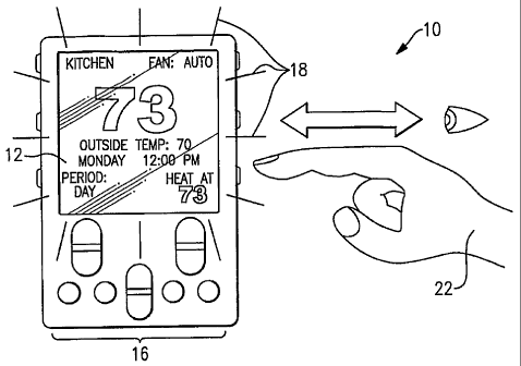
[0020] Referring to Figure 2, the thermostat 10 is shown schematically with
the
display device 12 illuminated by the illumination device 28 in a partially
illuminated mode
schematically shown by lines 18. In the partially illuminated mode 18 the
display device 12
can be viewed without interacting with any of the user interface controls 16.
A user 22 is
therefore able to determine and review the thermostat setting in a darkened
environment a
distance from the thermostat 10. Further, the partially illuminated mode 18
provided by this
invention generates substantially low levels of heat that does not affect
thermostat operation.
[0021] Referring to Figure 3, the thermostat 10 is shown in a fully
illuminated
state schematically shown by lines 20. This is a full-illumination mode 20
where the
illumination device 28 provides illumination greater than the partially
illuminated condition,
but only after actuation of the user interface 16 is detected. The full
illumination mode 20
provides for the actuation of the illumination device 28 in response to
actuation of the user
interface 16. Without user input, the normal or default condition of the
illumination device
28 is off or no-illumination. In the example thermostat 10, the full
illumination mode 20
actuates the illumination device 28 to provide maximum illumination responsive
to use of the
user interface 16. However, other illumination levels are within the scope of
this invention.
As appreciated, the illumination provided in the partial illumination
condition and the full
illumination condition is configurable and selectable by the user.
[0022] Full illumination of the display device 12 is initiated once the user
interface control 16 is actuated by the user 22. At such time as interaction
is detected, the
display device 12 is fully illuminated according to the full illumination mode
20. Once
interaction with the user interface 16 has terminated for a sufficient wait
period the fully
illuminated condition is ended and the display device 12 is no longer
illuminated. That is
CA 02572966 2007-O1-05
WO 2006/033783 PCT/US2005/030806
once the user 22 has completed programming or adjusting the parameters of the
thermostat
10, the illumination device 28 is simply turned off after a predetermined
time. As
appreciated, if interaction is required to cause actuation of the illumination
device 28 it is not
possible to view thermostat settings in a darkened environment until the user
interface 16 is
engaged. In some instances it is desirable to operate the thermostat in a mode
where the
display device 12 is not illuminated.
[0023] The example thermostat 10 has been described with a partially
illuminated
condition as one of two default conditions. The partially illuminated
condition and the fully
illuminated condition provide different light levels relative to one another.
Further although
two light modes are described, the levels of light emitted onto the display
device 12 can vary
as desired. The light level for the partially illuminated condition can
include a plurality of
modes and light levels. Further, the fully illuminated condition as pertains
to this description
and this invention is a light level greater than that of the partially
illuminated condition and
may also be varied as is desired according to application specific
requirements.
[0024] Referring to Figure 4, operation of the thermostat 10 occurs as is
shown in
the flow diagram illustrated at 48. The diagram 48 illustrates the process by
which the
microprocessor 30 operates the configurable illumination of the example
thermostat 10. This
set of decisions and actions is repeated consecutively during operation of the
thermostat 10.
An assessment begins with determining whether a key of the user interface
controls 16 has
been pressed as is indicated at 50. If a key has been pressed or any other
user interface
controls 16 have been pressed, the backlight timer will be initiated as is
shown at step 52 and
the illumination device 28 turned on. The backlight timer maintains
illumination for a
specific wait period responsive to interaction with the user interface control
16. The
6
CA 02572966 2007-O1-05
WO 2006/033783 PCT/US2005/030806
backlight timer will turn off the illumination device after a predetermined
wait period once no
interaction with the user interface 16 is detected. However, it the user
interface 16 is actuated
again the wait period is renewed. If operation continues the timer is
continually reset. It is
only after interaction with the user interface controls 16 stops that the wait
period expires and
operation proceeds to return the illumination device 28 to the default
condition.
[0025] If no interaction with the user interface is detected, the wait period
does
not begin and the illumination device 28 remains off as indicated at step 54.
An indication of
the current state of the back light timer is determined as is indicated at 56.
If the backlight
timer is active, the illumination device 28 will be engaged to the fully
illuminated condition
as is schematically indicated at 58. If the backlight timer is not actuated, a
determination of
whether the partial illumination mode 18 has been set as the default condition
is made as
schematically indicated at 60.
[0026] When the backlight timer is no longer active the microprocessor 30
determines what the current programmed default condition is and returns the
illumination
device 28 to the desired condition. If the partial illumination mode 18 is set
then the
illumination device 28 will return to the partially illuminated condition as
is indicated at 62.
If no backlighting is indicated and no illumination is the default condition,
the illumination
device is turned off as indicated at 64.
[0027] Once the default condition is restored, the thermostat 10 begins the
process
48 again from the return block 66. In this way the microprocessor 30 of the
thermostat 10
constantly updates the condition of the illumination device 28.
[0028] Referring to Figure 5, the thermostat 10 is initially set at a default
setting
where the illumination device 28 will fully illuminate the display device 12
for a
7
CA 02572966 2007-O1-05
WO 2006/033783 PCT/US2005/030806
predetermined amount of time. Full illumination is initially actuated because
programming
most often will follow initial installation of the thermostat I0. During
initial installation the
v° user 22 will select a default Lighting mode for the thermostat 10.
The initial user
configuration is schematically shown at 68.
[0029] The microprocessor 30 queries whether the initial backlighting setting
has
been initiated as is indicated by the decision block 70. If the partial
illumination mode 18 has
been indicated it will proceed to the partial backlighting configuration with
the new user
setting as is indicated by block 72. Then the microprocessor 30 will store the
current selected
modes within memory such that the memory reflects that the partial
illumination mode 18 has
been set by the user as the desired default condition as is schematically
shown at block 74. A
return 76 provides for continually updating to consider subsequent changes
made by the user
22.
[0030] Refernng to Figure 6, another thermostat 80 according to this invention
includes a lumen sensor 82. The lumen sensor 82 detects,a level of lighting
within a room or
the surrounding enviromnent. The lumen sensor 82 is as known, and provides a
signal
indicative of a light level surrounding the thermostat 80. As appreciated, in
some conditions,
lighting of the thermostat display device is not necessary, such as during the
day, or when the
surrounding area is illuminated by other lights. Accordingly, operation of the
therniostat 80
can be adjusted in accordance with current Lighting conditions. Operation of
the thermostat
80 according to the partial illumination mode 18 and the full illumination
mode 20 is then
modified according to light levels detected by the lumens sensor 82.
[0031] Referring to Figure 7, a block diagram 84 illustrates operation
responsive
to detection of light conditions with the lumen sensor 82. In a darkened
environment,
8
CA 02572966 2007-O1-05
WO 2006/033783 PCT/US2005/030806
operation would proceed normally according to the pre-selected default
condition. However,
operation is modified to account for a surrounding light level. In response to
the lumens
sensor 82 detecting light above a predetermined threshold value as is indicted
by decision
block 86, the illumination device is turned off.
[0032] Further, if the lumen sensor 82 detects light above the threshold
value, the
partial illumination condition can be deactivated. Once the light level drops
below the
threshold value, the lumen sensor no longer is active and partial illumination
condition is
engaged according to predetermined criteria. As appreciated, operation of the
illumination
device 28 with a lumens sensor 82 can include other modes of operation
according to desired
criteria, such as adjusting a level of illumination in a variable manner
according to light levels
surrounding the thermostat 10. Such operation may include increasing
illumination in a
lighted room to provide for greater contrast on the display device 12, or
lowering the light
levels for both the fully illuminated condition and the partially illuminated
condition for low
light conditions required less contrast to read the display device 12. A
worker with the
benefit of this disclosure will recognize that other operating modes utilizing
the lmnens
sensor 82 are within the scope and contemplation of this invention.
[0033] The thermostat 10 of this invention includes a configurable
illumination
device 28 that provides the user with selectable illumination modes. In the
partially
illuminated mode 18 the display device 12 is illuminated to a level that
allows for viewing of
thermostat information while not generating sufficient heat as to disrupt
measurement of
current ambient conditions. Further, upon actuation of any of the user
interface control 16
the illumination device 28 actuates to full illumination mode to provide the
user full visibility
during the setting of desired parameters. However, once the user has completed
any changes
9
CA 02572966 2007-O1-05
WO 2006/033783 PCT/US2005/030806
to the thermostat parameters the illumination device 28 returns to the
partially illuminated
default condition.
[0034] In the partially illuminated condition the user can review the status
of the
thermostat without engaging the thermostat. Further, the partially illuminated
mode 18
provides a nightlight to provide sufficient illumination in which to monitor
the thermostat and
walk through a darkened room without the need of turning other lighting.
[0035] Although a preferred embodiment of this invention has been disclosed, a
worker of ordinary skill in this art would recognize that certain
modifications would come
within the scope of this invention. For that reason, the following claims
should be studied to
determine the true scope and content of this invention.