Note: Descriptions are shown in the official language in which they were submitted.
CA 02573079 2007-01-05
WO 2006/002291 PCT/US2005/022173
METHOD AND SYSTEM FOR
POWER GENERATION
STATEMENT OF RELATED PATENT APPLICATION
This non-provisional patent application claims priority under 35 U.S.C. 119
to U.S.
Provisional Patent Application No. 60/582,314, titled Power Generator, filed
June 23, 2004.
The provisional application is hereby fully incorporated herein by reference.
FIELD OF THE INVENTION
The present invention relates to the field of power generation. More
particularly, the
present invention relates to a system comprising a flywheel magneto generator
having turbine
fan blades for increased power generation.
BACKGROUND OF THE .INVENTION
As the world's population expands and its economy increases, increased use of
fossil
fuels has raised atrnospheric concentrations of carbon dioxide, threatening
habitats and
causing climate changes. Even with improvements in efficiency and
environmental
protection, some experts say that atmospheric levels of carbon dioxide may be
double that of
the pre-industrial era by the end of the twenty-first century. While fossil
fuels are the basis
for many nations' economies, fossil fuels are a non-renewable resource that
will, at some
point, become harder and harder to obtain.
In an effort to discover sources of renewable energy, a great deal of research
has been
conducted into ways of generating electricity using wind, water, and solar
power. While
wind, water, and solar power have found limited application in specific areas
of the world,
none of these provides a cost-efficient power source in all areas of the U.S.,
much less the
world. In order to produce cost-efficient energy using wind-generated
electricity, a consistent
wind at speeds that can only be found in portions of California and certain
parts of the
Midwest is required. Hydro-electric power is only cost efficient in areas
where large dams
and sufficient water-sources are currently in place. Solar power cells have
never been able to
generate enough energy to reach the efficiency or scale many had hoped.
Automobiles are another source of carbon monoxide and carbon dioxide levels in
our
atmosphere. Some of the largest polluters are commercial vehicles operating
diesel engines.
CA 02573079 2007-01-05
WO 2006/002291 PCT/US2005/022173
In an effort to reduce pollution caused by some of these commercial vehicles,
some states are
instituting laws restricting the ability of commercial vehicles to idle for
hours at truck-stops
and rest areas. Absent having a power substation next door, most truck-stops
are not able to
provide sufficient power to the commercial vehicles in order to allow drivers
to get the
legislated amount of rest in their vehicles, while keeping the vehicle powered
at the truck or
rest stops.
In view of the foregoing, there is a need for a system of generating
electrical power on
both a small and large scale. There is a need for a power generating system
that is not
dependent on fossil fuels, sustainable winds, abundant water sources, or solar
technology.
There is also a need for a power generating system based on a power source
that is constant,
renewable, and reusable.
SUMMARY OF THE INVENTION
The present invention overcomes the problems of fossil-fuel use and the
deficiencies
of other renewable energy sources by providing a self contained power
generating system
that combines the power generating capabilities of a magneto flywheel and a
turbine system.
The magneto flywheel generates an initial level of electricity, capable of
starting one or more
blowers that can be used to generate high-velocity air pressure. The high
velocity air
pressure can be directed at a series of turbine fan blades, increasing the
power generating
levels of the system by increasing the rate at which a shaft of an alternator
is turned. The
alternator can then provide enough energy not only for the system but can also
act as an
energy source for external power systems. Because the source of electricity is
magnets and
air, the source of the electricity is clean, re-usable and is of an unlimited
supply.
For one aspect of the present invention, a horsepower accelerator wheel can be
attached to a drive shaft. The horsepower accelerator wheel can comprise
multiple magnets
along the circumference of the wheel and multiple turbine fan blades along the
outside of the
wheel, running from the circumference of the wheel towards the center-point of
the wheel.
The drive shaft can be attached to a motor, acting as a load balancer, and an
alternator, which
generates energy based on the speed of rotation of the drive shaft. A series
of blowers can be
positioned to provide high velocity air against the turbine fan blades and
large stationary
magnets can be positioned adjacent to the magnets on the circumference of the
wheel to
initiate the rotation of the wheel and the initial generation of electricity.
Another aspect of the present invention comprises a method of generating
electricity,
wherein stationary magnets are positioned adjacent to the rotational magnets
coupled to the
2
CA 02573079 2007-01-05
WO 2006/002291 PCT/US2005/022173
horsepower accelerator wheel in such a way as to induce rotation of the wheel.
The wheel
drives a shaft coupled to an alternator that generates a first level of
electricity. A portion of
the first level of electricity can be transmitted to a first blower to
generate high-velocity air
against a first set of turbine fan blades coupled to the wheel. The operation
of the first blower
against the first set of turbine blades increases the rotational speed of the
wheel, thereby
generating a second level of electricity at the alternator that is greater
than the first level. A
portion of the second level of electricity can be transmitted to the first
blower and a second
blower, wherein the second blower generates high-velocity air against a second
set of turbine
fan blades coupled to the wheel. The operation of the first blower and the
second blower
against the turbine blades further increases the rotational speed of the
wheel, thereby
generating a third level of electricity at the alternator that is greater than
the second level. A
portion of the third level of electricity can then be transmitted to extexnal
electrical
consumers.
BRIEF DESCRIPTION OF DRAWINGS
For a more complete understanding of the present invention and the advantages
thereof, reference is now made to the following description in conjunction
with the
accompanying drawings in that:
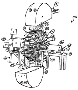
Fig. 1 depicts an angled view of an electrical power generation system in
accordance with an exemplary embodiment of the present invention;
Fig. 2 depicts a frontal view of the electrical power generation system in
accordance with an exemplary embodiment of the present invention; and
Fig. 3 depicts a section view of a horsepower accelerator wheel in accordance
with an exemplary embodiment of the present invention.
DETAILED DESCRIPTION OF THE EXEMPLARY EMBODIMENTS
The present invention supports the generation of electrical power through the
use of a
horsepower accelerator wheel as can be more readily understood by reference to
the
representative system illustrated in Figs. 1 and 2. Fig. 1 is a angled view of
an electrical
power generation system ("generator system") 100, in accordance with an
exemplary
embodiment of the present invention. Fig. 2 is a frontal view of the generator
system 100 in
accordance with an exemplary embodiment of the present invention. The
generator system
100 can include a motor 1 comprising a singe-phase or three-phase motor. The
motor 1 can
be designed to receive standard American (60 Hz.) or European (50 Hz.)
electricity. The size
3
CA 02573079 2007-01-05
WO 2006/002291 PCT/US2005/022173
of the motor 1 is generally determined based on the application or amount of
power that must
be generated by the system, however, any size motor 1 can be used. The motor 1
typically
acts as a load balancer for the generator system 100. In one exemplary
embodiment, the
motor 1 is a 3 horsepower, 110 volt, 60 hertz motor.
The motor 1 can be attached to a mounting platform 19 with fasteners, such as
nuts,
bolts, or screws, or can be welded, r'iveted, or attached using any other
attachment method
known in the art (not shown). The mounting platform 19 can comprise a table or
any other
stationary surface that allows a drive shaft of the motor 1(not shown) to be
substantially
parallel with a drive shaft 27. The motor drive shaft (not shown) can be
attached to the drive
shaft 27 with a coupling, welding, or other attachment methods known in the
art (not shown).
In one exemplary embodiment, the motor drive shaft (not shown) is attached to
the drive
shaft 27 using a spider coupling (not shown). In another exemplary embodiment,
the motor 1
can be directly attached to a horsepower accelerator wheel 3 with a coupling
(not shown) or
other attachment method known in the art.
The drive shaft 27 typically comprises a solid cylindrical shaft that is
attached to the
motor 1, horsepower accelerator wheel 3 and an alternator 6. The drive shaft
27 can
comprise a metal, alloy, plastic, or other element having characteristics of
high strength and
durability. In one exemplary embodiment, the drive shaft 27 comprises a
hardened stainless
steel shaft. The diameter of the drive shaft 27 is typically based on the size
of the horsepower
accelerator wheel 3 and the application the generator system 100 is being used
to power. The
length of the drive shaft 27 is typically dependent on the distance between
the motor 1 and
the alternator 6. In situations where the drive shaft length between the motor
1 and the
horsepower accelerator wheel 3 is more than insubstantial, the drive shaft 27
can pass
through a pillow block bearing 25 placed between the motor 1 and the
horsepower accelerator
wheel 3. The pillow block bearing 25 can be attached to a mounting bracket 20
with
fasteners, such as nuts, bolts, or screws, or can be welded, riveted, or
attached using any other
attachment method known in the art (not shown). The mounting bracket 20 can
comprise two
pieces of steel square tubing, running in the vertical direction attached
orthogonally to a
horizontal piece of steel square tubing at the top of the two vertical pieces.
The vertical and
horizontal pieces of the mounting bracket 20 can be attached to one another
with fasteners,
such as nuts, bolts, or screws, or can be welded, riveted, or attached using
any other
attachment method known in the art (not shown).
The drive shaft 27 is typically attached orthogonally to and passes through
the center-
point of the horsepower accelerator wheel 3 in such way that the horsepower
accelerator
4
CA 02573079 2007-01-05
WO 2006/002291 PCT/US2005/022173
wheel 3 will rotate about the axis of the drive shaft 27. The drive shaft 27
can be attached to
the horsepower accelerator wheel 3 with fasteners, such as nuts, bolts, or
screws, or can be
welded, riveted, or attached using any other attachment method known in the
art (not shown).
In one exemplary embodiment, a metal sleeve 28 is welded to the drive shaft
27. The drive
shaft 27 and metal sleeve 28 are then slid into and through the horsepower
accelerator wheel
3 and the metal sleeve 28 is welded to the horsepower accelerator wheel 3 to
provide the axis
of rotation.
As shown in Figs. 1 and 2, the horsepower accelerator wheel 3 can comprise a
right-
side wheel plate 3A, a left-side wheel plate 3B, multiple right-side turbine
fan blades 2
("right-side blades"), multiple left-side turbine fan blades 5 (left-side
blades"), multiple
gussets 26, and multiple rotational magnets 4. The overall radius of the
horsepower
accelerator wheel 3 is typically based on the load level of the alternator 6
and the amount of
power to be generated. The right-side wheel plate 3A and the left-side wheel
plate 3B can
each comprise a flat, circular, metallic plate having a circular hole bored at
the center-point of
the plate for accepting the drive shaft 27 and the sleeve 28. In one exemplary
embodiment,
the right-side wheel plate 3A and the left-side wheel plate 3B comprise 3/16
inch solid steel
plate, however other metal, alloys or plastics could be used in creating wheel
plates 3A and
3B.
Multiple magnet mounts 29 are attached orthogonally between and along the
circumference of wheel plates 3A and 3B. In one exemplary embodiment, the
magnet
mounts 29 are made of angle iron and faced together in pairs to create a U-
shaped cavity just
below the circumference of the horsepower accelerator wheel 3 so that when a
rotational
magnet 4 is placed into the cavity created by the mounts 29, the top of the
rotational magnet 4
is substantially equal with the circumference of the horsepower accelerator
wheel 3. Each
magnet mount 29 can be attached to wheel plates 3A and 3B with fasteners, such
as nuts,
bolts, or screws, or can be welded, riveted, or attached using any other
attachment method
known in the art (not shown).
Multiple rotational magnets 4 are attached to the magnet mounts 29 with
fasteners,
such as nuts, bolts, or screws (not shown). In one exemplary embodiment, the
rotational
magnets 4 are attached to a stainless steel plate (not shown) on the side of
the magnet 4
facing towards the center-point of the wheel 3. The stainless steel plate is
then bolted to the
magnet mounts 29. The rotational magnets 4 are placed along the circumference
of the
horsepower accelerator wheel 3 and spaced substantially equidistant from one
another. The
length of the rotational magnet 4 is typically greater than its width, with
the length being
CA 02573079 2007-01-05
WO 2006/002291 PCT/US2005/022173
considered the direction parallel to the drive shaft 27. Each rotational
magnet 4 typically
comprises a leading edge 38 having a polarity that is opposite from the
trailing edge 37 of the
rotational magnet 4, with the leading edge 38 comprising the edge of the
rotational magnet 4
that passes a point first based on rotation of the wheel 3. In one exemplary
embodiment, the
rotational magnet 4 has a leading edge 38 having a south polarity and a
trailing edge 37
having a north polarity. The rotational magnet 4 can be comprised of ceramic,
an earth
magnet, an electro-magnet, or any other type of magnet known in the art. In
one exemplary
embodiment the rotational magnets 4 comprise earth magnets made of load stone
based on
their ability to hold a consistent magnetic permeability. The rotational
magnets 4 can have a
flat surface or be machined to have a curvature substantially equal to the
circumference of the
horsepower accelerator wheel 3. In one exemplary embodiment, the distance
between
rotational magnets 4 is one inch, however, this distance can be greater or
less based on the
overall circumference of the horsepower accelerator wheel 3 and the strength
of the rotational
magnets 4 and/or the stationary magnets 18.
As shown in Fig. 1, multiple right-side blades 2 are attached substantially
orthogonally to the outside of wheel plate 3A. Multiple left-side blades 5 are
attached
substantially orthogonally to the outside of wheel plate 3B. The right-side
blades 2 and the
left-side blades 5 can be tapered in such a way that the blades 2 and 5 are
wider at the
circumference of the horsepower accelerator wheel 3 and get narrower as the
blades 2 and 5
get closer to the hub or center-point of the horsepower accelerator wheel 3.
The blades 2 and
can comprise any metal, alloy, plastic, or carbon-fiber element. In one
exemplary
embodiment, the blades 2 and 5 are comprised of sheet metal. The blades 2 and
5 are
designed to operate much like the sail of a sailing ship by catching air
generated by one or
more blowers 9, 10, 11, and 12. In one exemplary embodiment, the blades 2 and
5 are
cupped in the direction of the air flow to allow the blades 2 and 5 to catch
more air and
increase the speed of the horsepower accelerator wheel 3. The top of the
blades 2 and 5 can
be substantially equal to the circumference of the horsepower accelerator
wheel 3, however,
this is not necessary for proper operation of the generator system 100.
The blades 2 and 5 can be attached to the right-side wheel plate 3A and left-
side
wheel plate 3B with fasteners, such as nuts, bolts, or screws, or can be
welded, riveted, or
attached using any other attachment method known in the art (not shown). In
one exemplary
embodiment the blades 2 and 5 are each attached to a piece of sheet metal (not
shown) that is
substantially in the shape of the left-side 3B and right-side 3A wheel plates.
The sheet metal
piece can then be attached to the outer sides of the left-side 3B and right-
side 3A wheel plates
6
CA 02573079 2007-01-05
WO 2006/002291 PCT/US2005/022173
with fasteners, such as nuts, bolts, or screws, or can be welded, riveted, or
attached using any
other attachment method known in the art (not shown). In another exemplary
embodiment,
the right-side wheel plate 3A and the right-side blades 2 and the left-side
wheel plate 3B and
left-side blades 5 can comprise a single piece of metal, plastic, or other
material created from
a cast or mold. The space between each left-side blade 5 or right-side blade 2
typically
depends on the total circumference of the horsepower accelerator wheel 3. The
space
between blades 2 or 5 should generally be enough to allow air generated by
blowers 9, 10, 11,
and 12 to compress itself. In one exemplary embodiment, the right-side blades
2 are three-
inches apart and the left-side blades 5 are three-inches apart along the
circumference of the
horsepower accelerator wheel 3. The left-side blades 5 and the right-side
blades 2 are
typically positioned at the same points along the circumference of the
horsepower accelerator
wheel 3 so that there is substantially no offset, which could cause the
horsepower accelerator
wheel 3 to become imbalanced.
As shown in Fig. 1, a gusset 26 can be orthogonally attached between each
right-side
blade 2 and/or left side blade 5. The gusset 26 typically extends from the
trailing edge of one
blade 2 or 5 to the leading edge of the next blade 2 or 5. The gusset 26 also
can extend from
the outer-side of the right-side 3A or left-side 3B wheel plate to a point
substantially equal
with the outer edge of the tapered right-side blade 2 or left-side blade 5.
The gusset 26
provides increased strength for the blades 2 and 5. The gusset 26 can also
help to maintain
air pressure on the blades 2 and 5. The gusset 26 can be attached to the
blades 2 and 5 and/or
the right-side 3A or left-side 3B wheel plate with fasteners, such as nuts,
bolts, or screws, or
can be welded, riveted, or attached using any other attachment method known in
the art (not
shown). The gusset 26 can be attached to the blades 2 and 5 at any point along
the radius of
the right-side 3A and left-side 3B wheel plates. The gusset 26 can comprise
any metal, alloy,
plastic, or carbon-fiber element. In one exemplary embodiment, the gusset 26
comprises
sheet metal attached to the leading and trailing edge of the blades 2 or 5
with spot welds.
One or more covers 8 and 13 can be designed in such a way as to enclose the
horsepower accelerator wheel 3, one or more stationary magnets 17 and 18, and
one or more
blowers 9, 10, 11, and 12. The covers 8 and 13 can be mounted to the mounting
brackets 20
and 21 with fasteners, such as nuts, bolts, or screws, or can be welded,
riveted, or attached
using any other attachment method known in the art (not shown). Enclosing the
horsepower
accelerator wheel 3 with the covers 8 and 13 helps ensure that the only air
pressure the blades
2 and 5 receive is from the blowers 9, 10, 11, and 12. The covers 8 and 13
typically comprise
materials that have very low or no magnetic permeability, thereby limiting the
affect of
7
CA 02573079 2007-01-05
WO 2006/002291 PCT/US2005/022173
magnetic pull on objects outside of the covers 8 and 13. In one exemplary
embodiment, the
covers 8 and 13 comprise aluminum, however plastic, LEXAN, or other products
known to
one of ordinary skill in the art could be used. It should be noted that power
generated by the
generator system 100 is improved when the covers 8 and 13 are positioned as
close to the
horsepower accelerator wheel 3 as possible without making contact with and
causing drag on
the horsepower accelerator wheel 3. In one exemplary embodiment, the covers 8
and 13
comprise a two-piece design whereby each cover piece covers substantially half
of the
horsepower accelerator wheel 3. The two covers 8 and 13 can be attached
together with
fasteners, such as nuts, bolts, or screws, or can be welded, riveted, or
attached using any other
attaclnnent method known in the art (not shown). Furthermore, a gasket (not
shown) made of
neoprene or other material can be placed between the two covers 8 and 13 to
create an
improved seal.
As shown in Figs. 1 and 3, one or more blowers 9, 10, 11, and 12 can be
mounted (not
shown) inside of covers 8 or 13. The blowers 9, 10. 11, and 12 comprise a
motor 30 and an
output vent 31 (See Fig. 3). The blower motor 30 typically comprises an
electrical motor
capable of outputting air at a high velocity. The output vent 31 is typically
designed to
distribute the high velocity air along the width of the blades 2 and 5 at a
point substantially
equal to the circumference of the horsepower accelerator wheel 3, thereby
generating the
greatest amount of force against the blades 2 and 5 to cause the horsepower
accelerator wheel
3 to rotate at the highest possible speed. The blower motor 30 is electrically
coupled to a
breaker box 7, which provides electrical power to the blower motor 30 for
blowers 9, 10, 11,
and 12. In one exemplary embodiment, the blowers 9, 10, 11, and 12 are 5000
rpm blowers
operating at 110 volts. Furthermore, in the exemplary embodiment, four blowers
can be used
to generate air pressure against the blades 2 and 5. In this exemplary
embodiment, two
blowers 9 and 11 are positioned to provide air pressure against the left-side
blades 5 and two
blowers 10 and 12 are positioned to provide air pressure against the right-
side blades 2.
As shown in Figs. 1 and 3, one or more exhaust ports 14 can be attached to the
covers
8 and 13. The exhaust port 14 is mounted in such a way as to generate a vacuum
to pull and
remove the air from the backside of the right-side blades 2 and left-side
blades 5. By
removing all or substantially all of the air from the backside of the blades 2
and 5, drag on the
blades 2 and 5 is reduced. The number and positioning of exhaust ports 14 is
typically
determined by the application or use of the generator system 100 and the
positioning of the
blowers 9, 10, 11, and 12. The exhaust port 14 is typically the same width as
the blades 2 and
at the circumference of the horsepower accelerator wheel 3. A hole the width
of the
8
CA 02573079 2007-01-05
WO 2006/002291 PCT/US2005/022173
exhaust port 14 and approximately one-inch in height can be made in the cover
8 or 13. The
exhaust port 14 can be attached to the hole in the cover 8 or 13 with
fasteners, such as nuts,
bolts, or screws, or can be welded, riveted, or attached using any other
attachment method
known in the art (not shown). Further, a gasket (not shown) made of neoprene
or other
material can be placed between the cover 8 or 13 and the exhaust port 14.
As shown in Figs. 1 and 3, the exhaust port 14 is typically located above the
right-side
2 or left-side 5 blades in a position along the circumference of the
horsepower accelerator
wheel 3 between blowers 9 and 11 or 10 and 12 depending on which side of the
cover the
exhaust port is attached to. In one exemplary embodiment, an exhaust port 14
is attached to
the cover after each blower 9, 10, 11, and 12 in the generator system 100. The
exhaust port
14 is typically made of materials that very low or no magnetic permeability.
In one
exemplary embodiment, the exhaust port 14 comprises aluminum tubing extending
orthogonally away from the cover 8 or 13. In another exemplary embodiment, the
air pulled
away from the blades 2 or 5 by the exhaust port 14 can be piped back inside
the covers 8 and
13 and directed against the blades 2 and 5 to act substantially like a blower
9, 10, 11, and 12
using air piping that is well known in the art.
As shown in Figs. 1 and 3, one or more exhaust system tubes 15 can be attached
to the
covers 8 and 13 on one end and the exhaust port 14 on the other. The exhaust
system tube 15
typically comprises materials that have very low or no magnetic permeability.
In one
exemplary embodiment, the exhaust system tube 15 comprises aluminum tubing.
The
exhaust system tube 15 is typically the same width as the blades 2 and 5 at
the circumference
of the horsepower accelerator wheel 3. A hole the width of the exhaust system
tube 15 and
approximately one-inch in height can be made in the cover 8 or 13. The exhaust
system tube
15 can be attached to the hole in the cover 8 or 13 with fasteners, such as
nuts, bolts, or
screws, or can be welded, riveted, or attached using any other attachment
method known in
the art (not shown). Further, a gasket (not shown) made of neoprene or other
material can be
placed between the cover 8 or 13 and the exhaust system tube 15. A hole the
width of
exhaust system tube 15 and approximately one-inch in height can also be made
in the exhaust
port 14. The exhaust system tube 15 can be attached to the hole in the exhaust
port 14 with
fasteners, such as nuts, bolts, or screws, or can be welded, riveted, or
attached using any other
attachment method known in the art (not shown). Furthermore, a gasket (not
shown) made of
neoprene or other material can be placed between the exhaust port 14 and the
exhaust system
tube 15 to create an improved seal and further reduce the amount of air
escaping from the
wheel 3.
9
CA 02573079 2007-01-05
WO 2006/002291 PCT/US2005/022173
The exhaust system tube 15 is typically located above the right-side 2 or left-
side 5
blades in a position along the circumference of the horsepower accelerator
wheel 3 between
blowers 9 and 11 or 10 and 12 depending on which side of the cover the exhaust
port is
attached to. In the exemplary embodiment there is one exhaust tube 15 for each
blower 9, 10,
11, and 12. The exhaust tube 15 is typically located before the exhaust port
14, based on
direction or rotation of the horsepower accelerator wheel 3. The exhaust tube
15 can use the
vacuum generated by the exhaust port 14 to assist the exhaust tube 15 in
pulling air from the
backside of each blade 2 and 5.
As shown in Figs. 1, 2, and 3, stationary magnets 17 and 18 can be located
outside of
the circumference of the horsepower accelerator wheel 3. The stationary
magnets 17 and 18
can be ceramic, earth, electro-magnets, or any other type of magnet known in
the art. In one
exemplary embodiment earth magnets are used as stationary magnets 17 and 18
based on
their ability to maintain magnetic permeability for a longer period of time
than ceramic
magnets. The stationary magnets 17 and 18 typically have a stronger magnetic
force than the
rotational magnets 4. While two stationary magnets 17 and 18 are shown in Fig.
3, those
skilled in the art will understand that the actual number of stationary
magnets 17 and 18 can
be more or less based on factors such as the spacing between rotational
magnets 4, the
circumference of the horsepower accelerator wheel 3, and, the strength of the
stationary
magnets 17 and 18. In one exemplary embodiment, all stationary magnets 17 and
18 have the
same polarity. The stationary 17 and 18 magnets can have a north or south
polarity, and the
rotation of the wheel 3 can be reversed by changing the polarity of the
stationary magnets 17
and 18. The stationary magnets 17 and 18 are positioned above the
circumference of the
horsepower accelerator wheel 3 so that when stationary magnet 17 is creating a
magnetic pull
with the rotational magnet 4 closest to stationary magnet 17, stationary
magnet 18 is creating
a magnetic push with the rotational magnet closest to stationary magnet 18.
The stationary
magnets 17 and 18 are typically positioned within one-inch of the
circumference of the
horsepower accelerator wheel 3 and, as shown in Fig. 2, are typically as long
as the rotational
magnets 4.
As shown in Fig. 3, the stationary magnets 17 and 18 can be mounted in a
cradle 36,
inside the covers 8 and 13 and just outside the circumference of the
horsepower accelerator
wheel 3. The cradle 36 is orthogonally attached to vertical adjustment screws
34. The
vertical adjustment screws are threaded through a steel threaded plate 33,
which can be
mounted to the exterior of the covers 8 and 13. In one exemplary embodiment, a
gasket 35 of
neoprene or other like material is positioned between the steel threaded plate
33 and the cover
CA 02573079 2007-01-05
WO 2006/002291 PCT/US2005/022173
8 or 13 to reduce air lost inside the covers 8 and 13. The steel threaded
plate 33 can be
attached to the covers 8 and 13 with fasteners, such as nuts, bolts, or
screws, or can be
welded, riveted, or attached using any other attachment method known in the
art (not shown).
The cradle 36 can also be attached to horizontal adjustment screws (not
shown). The
horizontal adjustment screws can be threaded through a horizontal threaded
plate (not
shown). The horizontal threaded plate can be located outside of and attached
to the cover 8
or 13 with fasteners, such as nuts, bolts, or screws, or can be welded,
riveted, or attached
using any other attaclunent method known in the art (not shown). A gasket (not
shown) of
neoprene or other like material can be positioned between the horizontal
threaded plate (not
shown) and the cover 8 or 13 to reduce air lost inside the covers 8 and 13.
The cradle 36 typically comprises rubber, however other materials having low
or no
magnetic permeability could also be used. The cradle 36 can be adjusted in the
vertical
direction using the vertical adjustment screws 34 to move the stationary
magnets 17 and 18
closer to or further away from the circumference of the horsepower accelerator
wheel 3. The
horizontal adjustment screws (not shown) can be adjusted to move the
stationary magnets 17
and 18 in or against the direction of rotation. The adjustment of the position
of the stationary
magnets 17 and 18 increases the efficiency and starting capability of the
horsepower
accelerator wheel 3.
Returning to Figs. 1 and 2, as the drive shaft 27 exits the horsepower
accelerator
wheel 3 opposite the motor 1, the drive shaft 27 is attached to the alternator
6. In one
exemplary embodiment the alternator 6 is attached to drive shaft 27 through
the use of a
spider coupling (not shown), however one of ordinary skill in the art would
realize that other
methods of attachment, such as welding would be equally satisfactory. Through
the rotation
of the horsepower accelerator wheel 3 and the drive shaft 27, the alternator 6
generates
electrical power to power the blowers 9, 10, 11, and 12, the motor 1, and
additional
applications needing electrical power, such as a house or the cabs of
commercial vehicles.
The alternator 6 can be single-phase, three-phase or European. Exemplary
alternators 6 can
be used to generate amounts of electricity having a range in excess of 5,000
to 400,000 watts.
In one exemplary embodiment, a single-phase, 12 kilowatt alternator 6 is used
in the
generator system 100.
The alternator 6 can be attached to a mounting platform 22 with fasteners,
such as
nuts, bolts, or screws, or can be welded, riveted, or attached using any other
attachment
method known in the art (not shown). The mounting platform 22 can comprise a
table or any
other stationary surface that allows a shaft of the alternator 6 (not shown)
to be substantially
11
CA 02573079 2007-01-05
WO 2006/002291 PCT/US2005/022173
parallel with the drive shaft 27. The alternator 6 can be electrically coupled
to a voltmeter
39. The voltmeter 39 typically displays the amount of electrical voltage being
generated by
the alternator 6. In one exemplary embodiment, the voltmeter 39 is
electrically coupled to
the alternator 6 via three-phase wire encased in conduit 40.
The alternator 6 is electrically coupled to a breaker box 7. The breaker box 7
can be
attached to any surface with fasteners, such as nuts, bolts, or screws, or can
be welded,
riveted, or attached using any other attachment method known in the art (not
shown). The
breaker box 7 typically comprises a main breaker (not shown), a load box (not
shown), and
one or more semi-conductors (not shown). In one exemplary embodiment, the
alternator 6 is
electrically coupled to a breaker box 7 via three-phase wire encased in
conduit 24.
The breaker box 7 is electrically coupled to the blowers 9, 10, 11, and 12
(coupling
not shown) and the magnetic switch box 16 (coupling not shown). In one
exemplary
embodiment, the breaker box 7 is electrically coupled to the blowers 9, 10,
11, and 12 and the
magnetic switch box 16 with three-phase wiring encased in electrical conduit
(not shown).
The breaker box provides electrical power generated by the alternator for
blowers 9, 10, 11,
and 12 and the motor 1. The magnetic switch box 16 typically comprises one or
more
magnetic switches and capacitors to assist in starting the motor 1. In one
exemplary
embodiment, the magnetic switch box 16 is electrically coupled to the motor 1
via three-
phase wire encased in conduit 23.
It will be understood by those or ordinary skill in the art that while the
exemplary
embodiments have shown a generator system 100 wherein the horsepower
accelerator wheel
3 rotates in the vertical direction, it is well within the purview of this
invention to make minor
modifications so that the horsepower accelerator wheel 3 could rotate in the
horizontal or any
other direction based on needs of the user and space available.
In one exemplary embodiment, a method of generating power using the generator
system 100 typically begins by adjusting the horizontal (not shown) and
vertical adjustment
screws 34 to position the stationary magnets 17 and 18 in such a way that the
horsepower
accelerator wheel 3 begins to rotate. The horsepower accelerator wheel 3
typically begins to
rotate when the stationary magnets are moved closer to the circumference of
the wheel 3.
The rotation of the horsepower accelerator wheel 3 turns the drive shaft 27,
which turns the
shaft on the alternator 6 generating a minimum level of electricity.. Once a
minimum level of
electricity is being generated by use of magnets alone, a circuit breaker (not
shown) for one
of the blowers 9, 10, 11, and 12 at the breaker box 7 can be closed, allowing
the electricity
generated by the alternator 6 to be sent through the breaker box 7 to one of
the blowers 9, 10,
12
CA 02573079 2007-01-05
WO 2006/002291 PCT/US2005/022173
11, or 12. In one exemplary embodiment, once the voltmeter 39 displays a
reading of
approximately 80 volts, the first circuit breaker is closed. Electrical power
to the blower
motor 30 generates high velocity air which is, pushed through the blower vent
31 to drive the
right-side or left side turbine fan blades 2 or 5. The air being released
against the blades 2 or
increases the speed of the horsepower accelerator wheel 3, which in turn
increases the
rpm's of the drive shaft 27 and the total electricity generated by the
alternator 6. A second
circuit breaker for the blowers 9, 10, 11, and 12 at the breaker box 7 can be
closed allowing
the excess electricity to pass from the alternator 6 through the breaker box 7
to another
blower 9, 10, 11, or 12 that is not yet receiving electrical power. By adding
electrical power
to another blower 9, 10, 11, or 12, additional force is placed against the
turbine fan blades 2
and 5 and the speed of the horsepower accelerator wheel 3 increases. The
increase in speed
of the horsepower accelerator wheel 3 increases the rpm's of the drive shaft
27, thereby
increasing the amount of electricity generated by the alternator 6. The
circular process
continues until enough electricity is generated by the alternator 6 to power
all of the blowers
9, 10, 11, and 12. Once all of the blowers 9, 10, 11, and 12 are receiving
electricity, a circuit
breaker (not shown) for the motor 1 at the breaker box 7 can be closed,
allowing excess
electricity from the alternator 6 to pass through the breaker box 7 to the
motor 1. The motor
1 can be used for load balancing. In one exemplary embodiment, the horsepower
of the
motor 1 is substantially equal to eighteen percent of load. In alternative
embodiments, the
circuit breaker for the motor 1 can be closed before any of the circuit
breakers for the blowers
9, 10, 11, and 12, or after one or more circuit breakers for the blowers 9,
10, 11, and 12 have
been closed. Once all blowers 9, 10, 11, and 12 and the motor 1 are receiving
electricity, a
circuit breaker (not shown) can be closed at the breaker box 7 allowing excess
electricity,
generated by the alternator 6, to be passed through the breaker box 7 to
external systems as a
power source. In one exemplary embodiment, the circuit breakers can be closed
and opened
manually. In another exemplary embodiment, the passing of electricity to the
blowers 9, 10,
11, and 12, the motor 1, and to external systems can be controlled by a
programmable logic
controller of other control devices known the those of ordinary skill in the
art. In one
exemplary embodiment, the generator system 100 uses less than thirty percent
of the
generating head, allowing over seventy percent of the electricity generated by
the generator
system 100 to be used for external power needs.
In conclusion, the present invention comprises a completely self-contained
power
generating system 100. The invention allows for the generation of excess
electrical power
through the use of a horsepower accelerator wheel 3, a system of blowers 9,
10, 11, and 12,
13
CA 02573079 2007-01-05
WO 2006/002291 PCT/US2005/022173
stationary magnets 17 and 18, rotational magnets 4, and an alternator 6. The
excess
electricity generated by the generator system 100 can then be passed to
external systems
requiring electrical power without the need for fossil fuels or nuclear waste
from fission
reactors.
It will be appreciated that the present invention fulfills the needs of the
prior art
described herein and meets the above-stated objectives. While there have been
shown and
described several exemplary embodiments of the present invention, it will be
evident to those
skilled in the art that various modifications and changes may be made thereto
without
departing from the spirit and the scope of the present invention as set forth
in the appended
claims and equivalence thereof.
14