Note: Descriptions are shown in the official language in which they were submitted.
CA 02573089 2010-06-02
A ROTARY ELECTRICAL MACHINE BASED ON THE PRINCIPLE OF A
LINEAR MACHINE
The present invention relates to a machine that works like a permanent-
magnet radial-flux synchronous electric machine, having a stator consisting
of stator segments that function like linear machines.
In prior-art wind power stations, a wind rotor drives one or seldom two gen-
erators, generally via a gear system. As the wind rotor in larger wind power
plants typically rotates at 10 - 20 rpm, the gear system has a transmission
ratio close to 100 to give the generator a rotational speed of e.g. 1500 rpm.
In
wind mills provided with single-gear planetary gear systems, the transmission
ratio is close to 10, so the generator typically rotates at 150 - 250 rpm. An-
other type of generator known today is the so-called direct-driven generator,
which means that no gear system Is used at all and the wind rotor is con-
nected directly to the rotor of the electric machine.
A direct-driven radial-flux generator is disclosed in specification WO-Al-
00/60719, which describes a wind power generator that can be directly cou-
pled to the shaft of a wind rotor. The generator has a stator consisting of a
number of separate stator modules, which can be mounted, repaired and
removed separately and independently of the others. This allows easier in-
stallation of the wind power station and especially the generator, because the
stator can be transported and also mounted in place in smaller parts.
Specification WO-A1-03/073583 discloses a modular synchronous wind
power generator having a stator and rotor provided with windings, wherein
both the rotor and the stator consist of separate modules. In the modules,
both the stator and the rotor are composed from mutually superimposed
segment plates.
In the above-mentioned specification WO 03/073583, a method of building a
continuous stator ring is described. According to the claim, the stator ring
is
divided into at least two parts. Fig. 4 illustrates in particular how the ring
seg-
ments are locked together so as to form a continuous ring. The ring seg-
ments have at each end exactly a half tooth, so that these together form a
whole tooth. With this solution, the wind power generator can be assembled
from segments on site and wound with cable, and therefore a normal large
engineering works is not necessarily needed.
CA 02573089 2007-01-08
WO 2006/008331 PCT/F12005/000321
2
A drawback with prior-art wind power generators is their relatively complex
and weighty structure. Moreover, thermal expansion of the separate stator
and rotor modules and other similar factors cause difficulties in the installa-
tion and operation of the generator.
The object of the present invention is to overcome the drawbacks of prior art
and to achieve a solution which uses linear machines that are in principle
independent and, when connected mechanically in series, form a structure
1o which looks like a traditional segmental structure but which functionally
differs
significantly from the machine according to patent application WO 03/073583
representing a continuous stator structure.
The present invention is based on a principle whereby the stator of the elec-
tric machine consists of two or more separate independent segments resem-
bling a linear machine, which do not form a continuous ring that would be
part of the supporting structure of the machine. Therefore, the forces appear-
ing in the machine are compensated by a special supporting structure. In
prior-art solutions, the stator core is assembled from plates by laminating
them to form a continuous ring structure that functions as an "arch" bearing
part of the magnetic forces.
According to the invention, the linear machines are implemented using e.g.
five parallel stator plate packs, which form the magnetic circuit of a linear
machine.
The linear machine of the invention is secured e.g. with a T-bar to a support-
ing structure that bears all the forces. In prior-art solutions, the stator
seg-
ments are assembled by imbricating them so as to form a continuous ring,
which is generally welded by its back part to the frame structure of the ma-
chine. Thus, the stator pack forms an "arch" that is involved in supporting
the
magnetic forces.
As the magnetic cores of linear machines, unlike the magnetic cores of ordi-
nary machines, are not involved in supporting the magnetic forces of the
electric machine, we can therefore assemble the whole stator around a per-
manent magnet rotor already magnetized. Since the stator in a way consists
CA 02573089 2007-01-08
WO 2006/008331 PCT/F12005/000321
3
of independent linear machines, each of these can be deactivated or re-
placed when desirable.
In addition, a light structure and efficient cooling are achieved, and the
disad-
vantages caused by differences in the thermal expansion of separate stator
segments can be eliminated.
The features of the wind power generator of the invention are presented in
detail in the claims below.
In the following, the invention will be described in detail with reference to
an
example and the attached drawings, wherein
Fig. 1 presents a direct-driven wind power generator according to the
invention,
Fig. 2 presents the direct-driven wind power generator according to the
invention as a cross-section,
Fig. 3 presents a rotor,
Fig. 4 presents a stator segment and its supporting structure,
Fig. 5 presents a possible magnetic flux bridge,
Fig. 6 presents the frame of the magnetic circuit of the stator pack,
Fig. 7 presents permanent magnets,
Fig. 8 illustrates an arrangement according to the invention for imple-
menting the windings of the stator segment of e.g. a permanent-
magnet radial-flux generator so as to make each segment inde-
pendent and to allow them to be placed at small distances from
each other, and
Fig. 9 presents a possible other alternative for implementing the struc-
ture of the ends of the segment.
Figures 1 and 2 present a direct-driven three-phase generator functioning
substantially like a permanent-magnet radial-flux synchronous electric ma-
chine and designed for use in a wind power station, wherein the magnetic
flux flows in the radial direction between the stator and the rotor as in the
case of a permanent-magnet radial-flux synchronous electric machine, and
wherein the external arched stator consists of segments which in practice
work independently and which, when ready wound, can be called linear ma-
chines. The stator comprises e.g. 12 linear machines connected one after the
CA 02573089 2007-01-08
WO 2006/008331 PCT/F12005/000321
4
other in series, and the generator has a cylindrical casing 8 provided with
end
plates 3, a stator 2 and a rotor I and an external cabling 7 and a cooling sys-
tem 6 with piping arranged in the end of the generator. The rotor I can be
coupled directly to the shaft (not shown) of a wind rotor.
The generator is permanent-magnet synchronous generator in which the ro-
tor comprises a cylindrical outer part 31 and in which the frame is of
cellular
structure, consisting of plate-like end plate parts 32 and flange parts 33 be-
tween them, and a tubular central shaft 34 for connection to the shaft of the
wind rotor. The cylindrical rotor I is fitted inside the stator and provided
with
permanent magnets 35 fastened to its surface (Fig. 7), so it need not be pro-
vided with windings at all.
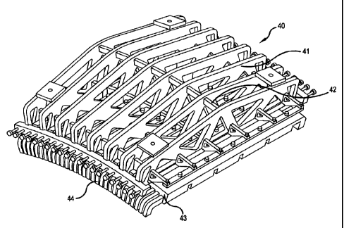
The stator has a number of linear machine segments 2, e.g. 12 segments
(Fig. 4), each of which segments is arranged at a small distance from the
others, and which have above them a cellular supporting frame structure 40
consisting of a plurality of perforated ribs 41 resembling bridge beams laid
in
the longitudinal direction of the generator and parts 42 placed between them,
wherein the stator segments are provided with successive stator winding
cores 43 provided with profiled copper windings 44 fitted in each stator seg-
ment, said cores having slots 47 and slot wedges 48 for the windings, and
wherein the stator packs thus formed are secured to the frame by a simple
moveable restraint, e.g. with a T-bar 45 comprised in the pack and counter-
parts 46 provided in its frame (Fig. 5 and 6).
In the solution of the invention, a magnetic flux bridge is provided between
the segments to connect the linear machines along the above-described
overhead frame structure to the generator when necessary by fastening a
downward-opening longitudinal U-channel beam 51 to the overhead frame
structure with a screw 52, in which channel beam is placed a magnetic flux
bridge bar 53 (Fig. 5) which maintains a rotary field even across the gap be-
tween the stator segments. The discontinuity between the linear machines
can also be alleviated by using a structure as illustrated in Fig. 9, wherein
the
iron part of the magnetic circuit is widened 49 at both ends of the linear ma-
chine so that the reluctance between the machines is reduced. The linear
machines are thus better coupled in series and the assembly begins to re-
semble a large rotary-field machine.
CA 02573089 2007-01-08
WO 2006/008331 PCT/F12005/000321
In the solution of the invention presented in Fig. 8, the winding at the edge
of
the stator segment 81 only fills part of the slot 82. This can be arranged
e.g.
by leaving the first and last slots 2 for each phase U, V, W half-filled, in
other
words, the last coils, which should return from the last slots back to the
slots
5 at the starting end, are left unmounted. By using a half-coil diamond
winding
arrangement 3, the end of the winding will be symmetrical between different
phases, and therefore no significant differences occur in phase inductance.
The coil end can be easily shaped in comparison with edgewise winding, and
no return leads are needed in the first slots at the starting end of the seg-
ment, space being thus saved at the coil end; in addition, the windings con-
tain no intersecting conductors, so the coil end can be made short.
The solution of the invention reduces the intensity of the magnetic field in
the
end areas of the linear machines - a magnetic discontinuity is present be-
tween the machines - so the end phenomena of the linear machines are
damped out.
The machine is assembled as follows:
1. The bearings and plates are mounted on the rotor.
2. The permanent magnets are mounted in the rotor, using special tools
by means of which the forces can be controlled.
3. The stator segments are carefully deposited one at a time into position
near the rotor, restraining them hydraulically or in some other suitable
controlled manner.
4. The supporting structures of the stator are fastened to the end shields.
This structure and this assembly procedure make it possible to build the ma-
chine almost anywhere. No separate machine factory is needed.
It is obvious to the person skilled in the art that different embodiments of
the
invention are not limited to the example described above, but that they may
be varied within the scope of the claims presented below. Besides a segment
consisting of successive packs, the stator segment can also be assembled
from a single part. In addition, some of the linear machines of the stator can
be removed from the machine or disconnected to deactivate them e.g. during
partial loads, in which case the machine will work without one or more seg-
ments.