Note: Descriptions are shown in the official language in which they were submitted.
CA 02573280 2007-01-04
6744P198 5 January 2006
Seal with support device
Description
The present invention relates to a closure for a container, having a support
device for the fillers.
Containers of the type under consideration here include in particular
cylindrical containers made
of plastic or glass, used for example as tubes for tablets. Therefore, the
present invention will be
explained in relation to the example of containers of this sort. However, the
description should
not for this reason be understood as limiting; rather, the present invention
can also be used for
any other containers, e.g. those having non-cylindrical cross-sections.
Such closures have long been known in the prior art, and are widely used for
example for closing
containers of vitamin tablets or food supplement tablets, as well as
pharmaceutical products,
whose fragility requires that there be support devices in the container or at
the closure in order to
ensure delivery of an undamaged product to the consumer. Such support devices
according to the
prior art generally use elastic elements that, in the delivered state of the
closed container, are
clamped between the closing cap and the contents and that exert a force on the
fillers in the
manner of a spring, damping externally caused agitation of the fillers and
thus preventing damage
to it.
DE 199 36 808 C2 discloses such an elastic element in the form of a bellows
that provides
segments between the closing cap and the fillers that expand radially and are
pushed together
axially when the elastic element is deformed, creating an elastic tension.
Such a bellows-type hold-down device is also described in DE-GM 79 29 377 Ul.
The
CA 02573280 2007-01-04
2
disadvantages of such a construction include comparatively high material and
manufacturing
costs. Another disadvantageous property of the bellows construction is that it
takes up a
relatively large volume inside the container, solely for the purpose of its
supporting function. The
occupation of such a large volume results in a comparatively high material
requirement, and thus
in higher costs. In addition, the container volume occupied by the elastic
element results in less
space for additional devices, such as for example a desiccating capsule for
placing desiccating
agents in the container.
Another construction of a support device that is widely used, e.g. in stopper
closures for vitamin
and food supplement tablet tubes, and that is proposed for example in DE-GM 83
37 183.4 Ul,
as well as in DE 196 33 495 Al, provides a holding down of the fillers in the
container via
elastically deformable spiral arms. Anchored on the inside of the closing cap,
a number of spiral
arms, uniformly distributed, wind down to a particular support depth, where
usually an annular
hold-down device is fastened. The advantage of such a construction is that the
interior volume is
available for additional functions, such as e.g. a desiccating capsule for
introducing a desiccating
agent into the container. A further disadvantage is the high material outlay
connected with the
use of a plurality of spiral arms and an annular hold-down device, resulting
in comparatively high
material costs.
The present invention is based on the object of creating a closure having a
support device that
removes the above-named disadvantages of the prior art, and in particular
offers a high degree of
user convenience and protection of contents.
According to the present invention, this object is achieved by the subject
matter of Claim 1.
Preferred developments of the present invention are subject matter of the
subclaims.
The closure according to the present invention achieves the object of the
invention by providing,
for holding down the fillers of a container having a container mid-axis, a
support device having
an elastically deformable support element that is capable of being brought
from a first position,
CA 02573280 2007-01-04
3
in which the support element is undeformed, into a second position in which
the support element
is deformed, whereas the support element has a contact area that, in the
second position,
transmits a supporting force to the fillers, and, in the second position, said
contact area of the
support element being situated closer to the container mid-axis than is the
case in said first
position. Here, the position of the support element in which it is still
undeformed, e.g. when the
closure is first placed into the completely filled container, is designated
the first position.
In the undeformed state, the support element is preferably geometrically
oriented in such a way
that it at least partly surrounds an imagined geometrical body, in particular
a cylinder, the
cylinder axis preferably being situated perpendicular to the upper side of the
closure.
In the closed state of the container, the cylinder axis preferably coincides
with the container mid-
axis.
The support element is advantageously constructed of one or more elastically
deformable struts
that are connected to the inside of the upper part of the closure. Thereby it
is possible that the
struts are connected to one another.
In order to achieve a low material requirement, a small number of struts is
preferably used,
additionally preferably having a small material thickness.
Moreover, it is preferably provided to define a directional dependency and
overall amount of the
elastic deformability of the support element through a material thickness that
can be changed
dependent on direction, and through the relative position of the struts to one
another. Particularly
preferably, essentially strip-shaped struts are used whose direction of
maximum deformability is
essentially perpendicular to the strip surface, this direction preferably
being, in the undeformed
state, essentially parallel to the surface of the imagined body, in particular
of the cylinder.
The struts can have a constant cross-section or can have an outer cross-
section that changes along
CA 02573280 2007-01-04
4
the strut, having a shape selected from a group of shapes including a
triangle, a rectangle, a
pentagon, a hexagon, or an n-gon, n being any number, and this group of shapes
can also include
an elliptical structure, an oval structure, or any other structure formed with
a curved outer line. In
particular for the contact area of the supporting element, a strut cross-
section is preferably
provided having a curved outer cross-section, in order for example to prevent
tilting of the
support element in contact with the fillers.
In a preferred embodiment of the closure, the support element has essentially
two struts,
designated the main support element and the auxiliary support element.
The main support element is essentially formed as an annular loop that is
preferably integrally
formed in one piece on the inside of the upper part of the closure in a first
connecting area, and
from there extends out in a plane parallel to the upper part of the closure.
The main support
element extending outward in this way is supported by the auxiliary support
element, which is
essentially formed as a two-armed partially annular loop integrally formed in
one piece to the
inside of the upper part of the closure in the area of a second connecting
area and in the plane of
the first connecting area, and whose arms extending out from there are each
integrally formed in
supporting fashion to one side of the annular loop of the main support
element. Here, the second
connecting area is preferably situated in the position of the first connecting
area, mirrored about
the axis of the imagined cylinder, and, in the undeformed state of the support
element, is
preferably situated perpendicular over the contact area of the annular loop of
the main support
element.
The deformability of the support element in the direction of the cylinder axis
is determined at
least partly by the deformability of the annular loop in the plane of the
surface that it spans. In
addition, the deformability in the contact area of the support element has a
component pointing in
the direction of the cylinder axis. These preferred directions of deformation
are supported by the
positioning of the auxiliary support element, which makes deformation of the
annular loop in a
direction parallel to the cylinder axis more difficult and allows its
deformation in the plane of the
CA 02573280 2007-01-04
annular loop and perpendicular to the cylinder axis. If a force now acts
parallel to the cylinder
axis on the contact area of the annular loop, e.g. due to pressing against the
surface of a tablet,
this annular loop is deformed in the annular loop plane, going out from the
contact area in the
direction towards the cylinder axis. In the example of the tablet surface, the
contact area slides in
the direction of the cylinder axis, and beginning from a particular point the
strip surface enters
into an angle to the cylinder axis that reinforces a sliding away of the
contact area in the direction
of the cylinder axis. In the closed position of the delivery state of the
closure for a container, the
support element is preferably in a position in which the contact area is
situated essentially on or
at least near the cylinder axis.
It is preferably provided that the support element can be integrally connected
to the inner surface
of the front wall of the upper part of the closure via a spacing element
situated essentially parallel
to the upper part of the closure. This spacing element preferably has a hollow
area; in particular,
the spacing element can be constructed essentially as a hollow cylinder.
The hollow area can be used in particular for fastening an additional device.
Here, locking means
are preferably provided on the interior wall of the spacing element, via which
the additional
device can be connected form closed and/or force closed to the spacing element
and thus to the
upper part of the closure. In particular, the locking means on the inner wall
of the spacing
element can be fashioned as a horizontally circumferential annular rib, and in
a number of ribs at
a distance running parallel to the cylinder. In addition, in particular the
horizontal circumferential
rib can be fashioned as a projection on the inner wall of the end of the
spacing element facing
away from the closure.
The additional device can in particular be a desiccating capsule containing a
desiccating agent
that acts hygroscopically, and that can counteract an absorption of water by
the fillers, e.g. in the
delivery state of a container closed by the closure according to the present
invention. In
particular, the locking means of the spacing element are constructed in such a
way that in its
hollow area desiccating capsules can be snapped in that are already
commercially available, e.g.
CA 02573280 2007-01-04
6
standard desiccating capsules having corresponding suitable locking means.
In addition, it is preferably provided that the closure be realized in the
manner of a stopper
closure, but other closure types may also be provided, e.g. screw closures or
bayonet closures.
The stopper closure preferred in the embodiment has, in the closed position of
the container, a
circumferential stopper wall that runs concentrically to the inner wall of the
container, and
protrudes from the inner surface of the front wall of the upper part of the
closure and is situated
between the spacer element, or support element, and the outer edge of the
upper part of the
closure. Due to the force-locked engagement of the stopper wall in the outlet
opening, the
container can preferably be closed in sealing fashion in such a way that under
normal conditions
of use the penetration of water vapor, gases, or liquids into the container is
largely prevented.
The outlet opening of the container preferably has a curved inner line that
can preferably be
ellipsoid, and more preferably circular. The container preferably has a curved
wall, and can in
particular have a hollow cylindrical construction.
In another preferred embodiment, the closure has a lower part that can be
fashioned as an
essentially annular container shoulder, the lower part of the closure
preferably concentrically
surrounding the outlet opening of the container. On the inside of the lower
part of the closure,
locking means are preferably provided by means of which the closure can be
connected form
closed and/or force closed to containers that have complementary locking
means. In particular,
these locking means can be provided on the lower part of the closure in the
form of a
circumferential groove and in the area of the outlet opening around the outer
wall of the container
in the form of a circumferential rib.
In addition, it is preferably provided that the closure has on its upper part
and on its lower part
means for forming a tamper-evident closure. These means can in particular be
fashioned in such
a way that on the upper part of the closure there is integrally formed a
radially outward-pointing
tongue that engages in a window, the window being formed by the opening
between a tear-off
CA 02573280 2007-01-04
7
ring segment situated concentrically around the outside of the lower part of
the closure and
connected thereto by connecting webs, and the connecting webs. The connecting
webs are
fashioned as the intended breakpoint, which break when the closure is brought
from the original
state into the state of use by detaching the tear-off ring segment from the
lower part of the
closure.
Advantageously, in the closed state of the closure the tongue pointing outward
from the upper
part of the closure can be used as an opening aid.
In addition, it is provided that preferably a plurality of such tongues and
windows, situated
concentrically around the upper part of the closure or around the lower part
of the closure, are
provided in order to form a tamper-evident closure, the tongues preferably
being capable of being
used as opening aids.
In a particularly preferred embodiment, the closure is constructed in the form
of a collapsible
closure, in which the upper part of the closure is connected pivotably with
the lower part of the
closure via a hinge.
In particular for the mostly preferred embodiment of the closure according to
the present
invention as a collapsible closure, the technical teaching of the present
invention proves to be
advantageous according to which the support area of the support element is
displaced in the
direction of the cylinder axis not until in its second position. Because this
area close to the axis
remains essentially accessible in the first position, more space is available
for pivoting the
closure and its support device into the outlet opening of the container. Here,
the support element
is preferably situated with the side of the contact area (i.e., the area
protruding furthest from the
plane of the upper part of the closure) close to the hinge and therefore close
to the outlet opening,
so that a large part of the outlet opening at the level of the hinge can be
used for the pivoting of
the contact area into the outlet opening. This arrangement results in an
advantageous
maximization of the support depth of the support device, i.e., a maximum
possible distance of
CA 02573280 2007-01-04
8
the contact area from the inner surface of the upper side of the closure.
The hinge of such a collapsible closure is preferably fashioned as a film
hinge, i.e., as a
connecting web having a low material thickness that connects the two parts of
the closure. This
connecting web is preferably elastically deformable, so that when the
connecting web is
deformed a reset force exists that can move the upper part of the closure
relative to the lower part
of the closure, back into its initial position, which can for example be the
position of the
completely opened closure.
The technical solution presented above for a closure having a support device
provides a
construction that can be used flexibly and that saves material and costs. It
is also economical if
the components of the closure can be manufactured in particular but not
exclusively in one piece,
from thermoplastic material, for example polyethylene or polypropylene, in the
known injection
molding method.
Additional advantages and features of the present invention result from the
following description
of the exemplary embodiment, in connection with the Figures.
Figure 1 shows the exemplary embodiment of the closure according to the
present invention in
the opened state, on a container that is realized as a hollow cylindrical
tablet tube.
Figure 2 shows the exemplary embodiment of the closure according to the
present invention in
the first position of the supporting element on a container realized as a
hollow cylindrical tablet
tube.
Figure 3 shows the exemplary embodiment of the closure according to the
present invention with
the second position of the supporting element on a container that is realized
as a hollow
cylindrical tablet tube.
CA 02573280 2007-01-04
9
Figure 4 shows the perspective view of the exemplary embodiment of the closure
according to
the present invention in the open state.
In the Figures, identical reference characters designate identical or similar
parts.
Figures 1 to 4 show the exemplary embodiment of a closure according to the
present invention
having a support device, in the preferred embodiment of the collapsible
closure.
Figure 1 shows the exemplary embodiment of the closure according to the
present invention in its
particularly preferred specific embodiment as a collapsible closure, having a
stopper sealing of
the closure and a tamper-evident closure system.
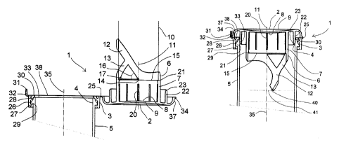
Closure 1 according to the present invention, made up of a closure upper part
2 having an
essentially circular outer cross-section and a closure lower part 3, is
connected to container 5 by
closure lower part 3 at the level of circular outlet opening 4. The closure
upper part has a support
element 6 that is connected to inner side 8 of front side 9 of the closure
upper part via a spacing
element 7.
In the exemplary embodiment, the front side is curved slightly in the
direction of the support
element, in the shape of a funnel. In the exemplary embodiment, the support
element partially
surrounds an imaginary cylinder 10 having a cylinder axis 11 that stands
perpendicular to inner
side 8 in the center of the upper part of the closure.
Support element 6 according to the present invention is preferably a
construction of struts having
a small material thickness that can be connected to one another; in the
exemplary embodiment
shown in the Figures, essentially two struts are provided, designated main
support element 12
and auxiliary support element 13.
As can be seen in particular in the perspective view shown in Figure 4, in the
exemplary
CA 02573280 2007-01-04
. ' r
embodiment main support element 12 is realized as an essentially strip-shaped
annular loop that
is integrally formed on spacing element 7 and that protrudes at two oppositely
situated sides of
the spacing element, extending from a first connecting area 14 at an angle 16
from a plane 15 that
is situated parallel to the upper side of the closure. The loop, protruding in
this way of main
support element 12 is supported by an essentially strip-shaped two-armed
partially annular loop,
the auxiliary support element 13, which, going out from a second connecting
area 17 on both
sides of the spacing element, is connected in one piece thereto and is
connected to the annular
loop of the main support element at the upper end of each of the loop arms.
Both the annular loop
of the main support element and also the partially annular loop of the
auxiliary support element
can have areas having different material thicknesses. These areas of different
material
thicknesses influence the deformability or rigidity of the support element
according to the present
invention.
Spacing element 7 preferably has in the exemplary embodiment locking means in
the form of
ribs 20 that are situated at a distance from one another in the direction
parallel to cylinder axis
11, and has a circumferential rib 21 that runs concentrically around the
inside of the end of
spacing element 7 facing away from the upper part of the closure. With the
spacing element,
realized in the exemplary embodiment as a hollow cylinder, a form closed
and/or force closed
connection can be formed to an additional device, in particular a desiccating
capsule. Such a
desiccating capsule is used in the original state of the container to protect
the fillers from
absorbing water.
In the exemplary embodiment, upper part 2 of the closure according to the
present invention also
has a stopper wa1122 that is fashioned essentially in the shape of a hollow
cylinder in order to
form a stopper-type seal on inner side 8 of the upper side of the closure, and
that has, on its side
facing away from the upper part of the closure, a beveling 23 that facilitates
the engagement of
the stopper wall in outlet opening 4 of container 5. Through the engagement of
the stopper wall
in the outlet opening, in the closed state the container is sealed in such a
way that it is protected
against the entry of, for example, water vapor, gases, or liquids.
CA 02573280 2007-01-04
I1
In addition, the upper part of the closure has a stepped area 37 by which the
front side 9 of the
upper part of the closure is offset in relation to support plane 38.
Closure upper part 2 is connected to closure lower part 3 by a hinge; in the
exemplary
embodiment, the hinge is realized as a film hinge 25 that is formed by a
connecting web made
from the elastic production material having a small thickness. In the
exemplary embodiment, this
connecting web is elastically deformed when the closure is closed, so that a
reset force acts on it
that, when the container is opened, effects or at least supports a guiding of
the upper part of the
closure back into the initial position of Figure 1.
Lower part 3 of the closure according to the present invention, having an
essentially circular
outer cross-section, has a circumferential groove 26 that runs concentrically
on the inner side of
the lower part of the closure, formed on the inner side of the lower part of
the closure by
protrusions 27 and 28 that run concentrically on the inner surface. In the
exemplary embodiment,
the container has on its upper edge a circumferential rib 29 by means of which
the lower part of
the closure, and thus the closure as a whole, can be connected to the
container with form closed
and/or force closed connection. In addition, the lower part of the closure has
on its inner surface
on the upper edge a projection 30 by means of which the lower part of the
closure can lie against
the upper edge of the container, and that defines on its upper side support
surface 38.
In addition, in the exemplary embodiment a device is provided for the tamper-
evident closure of
the closure according to the present invention. For this purpose, on the
outside of the lower part
of the closure a window 32 is fashioned in a position that corresponds
approximately to the
position of film hinge 25 mirrored about container mid-axis 35; this window is
formed by the
opening between the closure lower part 3 and a tear-off ring segment 31
situated concentrically
around the outer side of closure lower part 3 and connected thereto by
connecting webs 36. In the
closed original state of the container, this opening is sealed in that tongue
34 on the outside of
closure upper part 2 engages in window 32, and in that in this original state
the closure can be
CA 02573280 2007-01-04
12
opened only by breaking the connecting webs, which are formed as intended
breakpoints. Tongue
34, which in the closed state extends from the outer side of the closure, can
also be used as an
opening aid, in that it offers a starting point for grasping the upper part of
the closure in the
closed state, and acts as a force-amplifying lever during opening.
In the exemplary embodiment, this tamper-evident closure system is made up of
one window and
one tongue. However, it is possible for a plurality of windows and tongues to
be fashioned in
order to form the tamper-evident closure system.
In Figure 2, the first position of the support element is illustrated in the
exemplary embodiment
having the closure according to the present invention realized as a
collapsible closure. The
support element has a contact area 40 that in the undeformed state of the
support element defines
the point of maximum distance of the support device perpendicular to the
support plane 38, and
thus defines the maximum support depth of the support device. In this first
position of the
support element, in the exemplary embodiment contact area 40 impinges on upper
surface 41 of a
stack of tablets.
As the process of closing the container continues, the pressure force of the
stack of tablets
deforms annular loop 12 at least partly in the direction of cylinder axis 11,
so that at least a
partial displacement or sliding of contact area 40 in the direction of
container axis 35 takes place.
In the completely closed state of the container, e.g. in the original state,
in the exemplary
embodiment contact area 40 is situated close to container mid-axis 35. In this
second position of
the support element, main support element 12 of support element 6 is maximally
deformed and is
deflected in the direction of container mid-axis 35 or cylinder axis 11. This
is shown in Figure 3.
Figure 4 shows a perspective view of the exemplary embodiment of the closure
according to the
present invention in its specific embodiment as a collapsible closure, in the
opened state of the
container, i.e. as in Figure 1. Figure 4 illustrates the annular loop of main
support element 12, as
well as its strip shape. In addition, on the outer side of lower part 3 of the
closure, tear-off ring
CA 02573280 2007-01-04
13
segment 31 can be seen clearly, which is connected to the lower part of the
closure by connecting
webs 36 and which forms with the connecting webs a window 32 for the
engagement of tongue
34, this window and this tongue forming at least a part of the tamper-evident
closure device.