Note: Descriptions are shown in the official language in which they were submitted.
CA 02573449 2007-01-10
WO 2006/022615 PCT/US2004/023368
GOLF CLUB HEAD
Related Applications
This application is related to PCT/US 03/11085 filed on April 11, 2003, the
disclosure of which, in its entirety, is incorporated herein by reference.
Technical Field and Back2round Art
The present invention relates to golf club heads and, more particularly, to
the design
of golf club heads.
In general, golf club heads are designed as either solid bodies (for example,
persimmons), plates (for example, irons and putters with perimeter weights),
or shells with a
diaphragm face (for example, metal drivers and fairway woods). Today, the
general
consensus is that a shell with a diaphragm face provides the optimal design
solution for a
golf club head, with incremental improvements on that design helping to
improve how far
and how accurately a golfer can hit the golf ball.
For example, as discussed in U.S. Patent No. 6,348,015, the face of a "shell"
golf
club head is designed from a material having a natural frequency between 2800
Hz and 4500
Hz. Upon hitting the material, the golf ball undergoes smaller deformations
and, hence,
lower energy losses. Or, as discussed in U.S. Patent No. 6,348,013, a "shell"
golf club head
is designed with one or more recesses in one or more of the head's walls. The
recesses
increase the amount of time the face of the head remains in contact with the
ball, again
reducing energy loss.
Similarly, in U.S. Patent No. 6,267,691, the face of a "shell" golf club is
reinforced
with parallel ribs along the back side of the face, controlling how the face
bends under
impact load. The ribs help resist bending of the face in a direction parallel
to the ribs, but
permit bending of the face in a direction perpendicular to the ribs. The
reinforcing ribs help
dampen the head's vibrations and give the face a larger region in which there
is an efficient
transfer of energy from the face to the ball (known as the "sweet spot").
1
CA 02573449 2007-01-10
WO 2006/022615 PCT/US2004/023368
Summary of the Invention
In accordance with one aspect of the invention, a golf club head comprises a
face, an
inertial support system, a rear structure, and a force transfer system. Under
impact load, the
force transfer system elongates the rear structure and controls, in
cooperation with the inertial
support system, the bending of the face, the pattern of bending of the face
being a
substantially bridge-like, or substantially modified bridge-like, pattern of
bending.
In a further embodiment of the invention, the rear structure cooperates with
the force
transfer system and the inertial support system in controlling the bending of
the face, the
pattern of bending of the face being a substantially bridge-like, or a
substantially modified
bridge-like, pattern of bending. In another further embodiment of the
invention, during an
off-center impact load, a part of the face moves forward relative to the
inertial support
system. In an additional embodiment of the invention, the force transfer
system and the rear
structure control the forward movement of the face.
In still another embodiment of the invention, the golf club head further
comprises a
torsion control system, which is operatively connected to the inertial support
system. The
torsion control system may comprise a cross-brace, an insert, some combination
of a cross-
brace and an insert, or some combination of a cross-brace and a portion of an
insert. The
insert may have a wall thickness that is constant, multiple, varying or
profiled. In addition,
the torsion control system may be re-configurable or replaceable.
In alternate embodiments of the invention, the inertial support system may
include a
hosel, and the mass of the inertial support system may be at least equal to
the combined mass
of the face, the force transfer system and the rear structure. Also, the
inertial support system,
the force transfer system, the face, the rear structure or the torsion control
system may each
be an integral unit, or some combination of the inertial support system, the
force transfer
system, the face, the rear structure or the torsion control system may be an
integral unit. In
addition, the force transfer system may be separated into one or more
portions.
In further embodiments of the invention, the force transfer system may be the
crown
of the golf club head, the sole of the golf club head, or a combination of the
crown and sole
of the golf club head. Or, a part of the force transfer system may be the
crown of the golf
club head, the sole of the golf club head, or a combination of the crown and
sole of the golf
club head. In addition, the golf club head may include a conventional crown or
a
2
CA 02573449 2007-01-10
WO 2006/022615 PCT/US2004/023368
conventional sole. The conventional crown or conventional sole may be composed
of a
thermoset elastomer, a thermoplastic elastomer, or an engineering plastic. The
thermoset
elastomer, thermoplastic elastomer, or engineering plastic may be combined
with fillers or
fibers, such as glass or carbon, to form a composite structure. Also, the
conventional crown
or conventional sole may be transparent (in whole or in part) or translucent
(in whole or in
part).
In accordance with another aspect of the invention, a golf club head comprises
a face
and a substantially non-deforming mass connected to the face. Under impact
load, the
contact forces from the impact load, in connection with the resulting inertial
reaction forces
from the substantially non-deforming mass produce a pattern of bending of the
face that is a
substantially bridge-like, or substantially modified bridge-like, pattern of
bending.
In accordance with still another aspect of the invention, a golf club head
comprises a
face, an inertial support system, a rear structure, and a force transfer
system. Under on-center
impact load, the force transfer system may be placed in a state of
substantially pure axial
compression.
In a further embodiment of the invention, the rear structure may be placed in
a state
of substantially pure axial tension under on-center impact load.
In accordance with a further aspect of the invention, a golf club head
designed to act
under impact load as a bridge comprises a face, the face acting as a bridge
span; an inertial
support system, the inertial support system acting as a bridge support; a rear
structure and a
force transfer system, the force transfer system and the rear structure acting
together as a
bridge truss.
Brief Description of the Drawings
The foregoing features of the invention will be more readily understood by
reference
to the following detailed description, taken with reference to the
accompanying drawings, in
which:
Figure 1 is a schematic top view of an exemplary embodiment of a golf club
head
designed to act, under impact load, as a bridge.
Figure 2 is a schematic top view of an exemplary embodiment of a golf club
head
designed to act, under impact load, as a bridge.
3
CA 02573449 2007-01-10
WO 2006/022615 PCT/US2004/023368
Figure 3 is a schematic top view of an exemplary embodiment of a golf club
head
designed to act, under impact load, as a bridge.
Figure 4 is a schematic top view of an exemplary embodiment of a golf club
head
designed to act, under impact load, as a bridge.
Figure 5 is a schematic top view of an exemplary embodiment of a golf club
head
designed to act, under impact load, as a bridge.
Figure 6 is a schematic side view of an exemplary embodiment of a golf club
head
designed to act, under impact load, as a bridge.
Figure 7a is a schematic top view, and Figure 7b is a sectional view, of an
exemplary
embodiment of a golf club head designed to act, under impact load, as a
bridge.
Figure 8 is a schematic top view of an exemplary embodiment of a golf club
head
with an exemplary embodiment of a torsion control system, the golf club head
designed to
act, under impact load, as a bridge.
Figure 9 is a schematic top view of an exemplary embodiment of a golf club
head
with an exemplary embodiment of a torsion control system, the golf club head
designed to
act, under impact load, as a bridge.
Figure 10 is a schematic top view of an exemplary embodiment of a golf club
head
with an exemplary embodiment of a torsion control system, the golf club head
designed to
act, under impact load, as a bridge.
Figure 11 a and Figure 1 lb are schematic side views of an exemplary
embodiment for
a torsion control system used in a golf club head designed to act, under
impact load, as a
bridge.
Figure 12a and Figure 12b are graphs showing the pattern of bending in golf
club
heads according to embodiments of the invention in comparison to diaphragm
golf club
heads.
Detailed Description of Specii:ic Embodiments
In accordance with one embodiment of the invention, a golf club head is
designed to
act as a "bridge" when the golf club head impacts a golf ball during game play
(referred to
hereinafter as "under impact load"). In general, the face of the golf club
head corresponds to
the bridge span, with the bridge truss and the bridge inertial supports
located behind the face.
4
CA 02573449 2007-01-10
WO 2006/022615 PCT/US2004/023368
As such, the bridge-like golf club head designs described herein are minimum
weight
structures that are inertially-supported under dynamic loading.
For ease of reference, the term "bridge" is used herein to refer to both a
bridge
structure and a modified bridge structure. In a bridge structure, most, if not
all, of the
characteristics of the structure are similar to the characteristics of a
bridge-with few, if any,
of the characteristics of other structures, such as a solid body, a plate, or
a shell with a
diaphragm face. In a modified bridge structure, some, but not all, of the
characteristics of the
structure are similar to the characteristics of a bridge-with additional
characteristics of other
structures, such as a solid body, a plate, or a shell with a diaphragm face.
In general, a golf club head designed to act, under impact load, as a bridge
may have
a sweet spot that extends across the height of the face of the golf club head
and a center of
mass that may be closer to the face of the golf club head. The bridge truss,
located behind the
face, may be tailored to provide a particular rate of deflection under impact
load, and the
bridge inertial supports may be tailored to provide a particular moment of
inertia.
Furthermore, the mass of the golf club head needed to support the impact load
may be less
than the mass needed in a "shell" golf club head. This leaves more mass
available to
optimize the inertial performance of the golf club head.
Figure 1 is a schematic of an exemplary embodiment of a golf club head
designed to
act, under impact load, as a bridge. In golf club head 100, face 110 is
connected to inertial
support system 120 and force transfer system 130. In turn, rear structure 140
is connected to
force transfer system 130 and face 110. Force transfer system 130 comprises
two component
parts, inner structure 130a and radial structure 130b.
For ease of reference, the term "connection" is used herein to refer to
physical
connections between structures, as well as operational connections between
structures. For
example, the statement that structure A is connected to structure B may mean:
(1) structure A
is physically attached to structure B; (2) structure A interacts with
structure B under
operational conditions; or (3) structure A is physically attached to structure
B and structure A
interacts with structure B under operational conditions.
Inertial support system 120, connected to the left side edge and right side
edge of face
110, provides support for the "bridge structure" of golf club head 100. The
bridge structure is
that part of golf club head 100 required to support the impact load of a golf
ball-face 110,
5
CA 02573449 2007-01-10
WO 2006/022615 PCT/US2004/023368
force transfer system 130 and rear structure 140. Under impact load, the
bridge structure
transfers load to inertial support system 120.
Under an off-center impact load, inertial support system 120 also opposes the
"rotation" of golf club head 100 resulting from the off-center impact load.
For example,
when a golf club head hits a golf ball somewhere between the center of the
face and the toe
of the golf club head, the golf club head will rotate about a vertical axis.
In turn, the golf ball
will travel in an unintended direction. With opposition, such as that provided
with inertial
support system 120, the rotation of the golf club head is reduced. In other
words, inertial
support system 120 produces high moments of inertia for golf club head 100.
In general, under impact load, force transfer system 130, in connection with
inertial
support system 120, elongates rear structure 140, controls the "bending" of
face 110 (and
thus the deflection of face 110), and controls the rate of deflection of face
110. For example,
force transfer system 130 and inertial support system 120 may control the rate
of deflection
of face 110 at the same rate of deflection of a golf ball hit at a particular
swing velocity,
thereby achieving a good dynamic response and an impedance match between face
110 and
the golf ball. In golfer parlance, a good impedance match means a good driving
distance for
the golf ball. In an alternate embodiment of golf club head 100, rear
structure 140 may also,
in connection with force transfer system 130 and inertial support system 120,
control the
bending of face 110 and control the rate of deflection of face 110.
In addition, under an on-center impact load, with force transfer system 130
and rear
structure 140 acting substantially in the manner of a bridge truss, force
transfer system 130
and rear structure 140 are placed in a state of either substantial axial
compression or
substantial axial tension. In particular, inner structure 130a and radial
structure 130b are
placed in a state of substantial axial compression (a "push" along the length
of a structure)
and rear structure 140 is placed in a state of substantial axial tension (a
"pull" along the
length of a structure).
Under all impact loads, on-center and off-center, face 110 bends under the
impact. As
shown in Figure 12a, however, the pattern of bending differs from the pattern
of bending
seen in the face of a"drum" golf club head. In a drum golf club head, also
referred to herein
as a diaphragm golf club head, the pattern of bending of the face as measured
along a vertical
line (in relation to the horizon) from the top edge of the face to the bottom
edge of the face is
6
CA 02573449 2007-01-10
WO 2006/022615 PCT/US2004/023368
not uniform. In other words, along a vertical line Ao to Alo, the rearward
deflection of Ao
may not equal the rearward deflection of Al, the rearward deflection of AI may
not equal the
rearward deflection of A2, the rearward deflection of A2 may not equal the
rearward
deflection of A3, etc. The reason for the non-uniform bending is inherent in
the diaphragm
golf club head's design, which requires rigid connections of the face along
its top, bottom
and side edges.
In golf club head 100, the pattern of bending of face 110 is substantially
uniform
from the top edge of the face to the bottom edge of the face, as measured
along a vertical line
(in relation to the horizon) (hereinafter referred to as "bridge-like pattern
of bending"). In
other words, along a vertical line Bo to Blo, the rearward deflection of Bo is
substantially
equal to the rearward deflection of B 1, the rearward deflection of B 1 is
substantially equal to
the rearward deflection of B2, the rearward deflection of B2 is substantially
equal to the
rearward deflection of B3, etc. Thus, in comparison to a diaphragm golf club
head, which has
a sweet "spot" (defined as a single point on the face of the diaphragm golf
club head), face
110 has a sweet "line" (defined as a series of points on face 110 of golf club
head 100). The
"sweet" region on the face of a golf club head is, in part, the region
optimized to have
efficient transfer of energy from the face of the golf club head to the golf
ball.
A person of skill in the art understands that the phrase "along a vertical
line (in
relation to the horizon)" is used for ease of reference. In operation, in many
golf club heads,
the vertical axis of the club face may not be perpendicular to the horizon.
Instead, the vertical
axis of the club face may be angled in relation to the horizon (for example,
oriented in
relation to a particular "hit" distribution). Thus, in such a club face, the
bridge-like pattern of
bending may occur along a line substantially parallel to the vertical axis of
the club face. In
addition, in many golf club heads, the face of the golf club head may not be
planar (for
example, the face may have a roll). In such a club face, the bridge-like
pattern of bending
may occur along a line substantially tangential to the curved face of the golf
club head. In
other words, a bridge-like pattern of bending is a pattern of bending of face
110 that is
substantially uniform from near the top edge of face 110 to near the bottom
edge of face 110,
as measured along a vertical line (in relation to the horizon), as measured
along a line
substantially parallel to the vertical axis of face 110 (which may not be
perpendicular to the
horizon) or as measured along a line substantially tangential to a curve in
face 110.
7
CA 02573449 2007-01-10
WO 2006/022615 PCT/US2004/023368
In an alternate embodiment of golf club head 100, the pattern of bending of
face 110
is a "modified" bridge-like pattern of bending. In a modified bridge-like
pattern of bending
the maximum deflections (and rates of deflection) at various points of impact
for various
impacts, which occur over a substantial area of the face, have approximately
the same value.
In other words, in an area C of the face, the rearward deflection Zl from
impact Il (which
occurs at point [Xl, Yl] on the face) is substantially equal to the rearward
deflection Z2 from
impact I2 (which occurs at point [X2, Y2] on the face), the rearward
deflection Z2 from impact
I2 is substantially equal to the rearward deflection Z3 from impact 13 (which
occurs at point
[X3, Y3] on the face), the rearward deflection Z3 from impact 13 is
substantially equal to the
rearward deflection Z4 of impact I4 (which occurs at point [X4, Y4] on the
face), etc. Thus,
despite the fact that impacts Il, I2, 13 and 14 are all at different points on
face 110, the
deflections from the impacts are substantially equal, such that Zl ;Z~ Z2 z Z3
z Z4 ...z Zn.
In addition, the rates of deflections from the impacts are also substantially
equal, such that
Z1~Z2 Z Z3= Z4...= Zn.
In contrast, as shown in Figure 12b, in a diaphragm golf club head, the
maximum
deflections (and rates of deflection) at various points of impact for various
impacts, which
occur over a substantial area of the face, do not have approximately the same
value. In other
words, in an area D on the face, the rearward deflection Zl from impact Il
(which occurs at
point [X1,Y1] on the face) is not substantially equal to the rearward
deflection Z2 from impact
12 (which occurs at point [X2, Y2] on the face), the rearward deflection Z2
from impact I2 is
not substantially equal to the rearward deflection Z3 from impact 13 (which
occurs at point
[X3, Y3] on the face), the rearward deflection Z3 from impact 13 is not
substantially equal to
the rearward deflection Z4 of impact Iq (which occurs at point [X4, Y4] on the
face), etc.
Thus, in a diaphragm golf club head, the deflections from the impacts are not
substantially
equal, such that Zl ~ Z2 ~ Z3 ~ Z4 ...;6 Z. In addition, the rates of
deflection from the
impacts are also not substantially equal, such that Zl ~ Z2 ~ Z3 ;4 Z4 ...~6
Zn.
In one embodiment of the invention, the "sweet" area of face 110 is more than
approximately 25% of the area of face 110. In all embodiments for the sweet
regions (both
lines and areas) of face 110, the regions may be angled to better match the
golf impact
distribution for a particular golfer (or a group of golfers). For example, the
sweet regions of
face 110 may be angled at 30 from the horizontal.
8
CA 02573449 2007-01-10
WO 2006/022615 PCT/US2004/023368
As discussed, under an off-center impact load, face 110 bends with the bridge-
like
pattern of bending. In addition, during an off-center impact load, a part of
face 110 moves
forward relative to inertial support system 120. Typically, the part of face
110 that moves
forward relative to inertial support system 120 is opposite from the side of
face 110 impacted
by the golf ball. It is believed that the forward movement of face 110 under
an off-center
impact load, which the force transfer system and the rear structure control,
accounts for one
of the great characteristics of a bridge-like golf club head-the ability to
drive the golf ball in
its intended direction even though the golfer hit the golf ball off the center
line of face 110.
In an alternate embodiment of golf club head 100, face 110 includes a "hinged"
portion (or portions) that flex(es), acting as a hinge. The hinged portion,
typically located to
the right side edge or left side edge of face 110, flexes under impact load.
In other words, the
hinged portion of face 110 rotates about the connection of face 110 and
inertial support
system 120.
In a further alternate embodiment of golf club head 100, the mass of inertial
support
system 120 is greater than, or equal to, the combined mass of face 110, force
transfer system
130 and rear structure 140. Thus, in this alternate embodiment of golf club
head 100, at least
50% of the mass of golf club head 100 may be used to optimize moment of
inertia values for
golf club head 100.
In still further alternate embodiments of golf club head 100, face 110 may not
be
physically connected to inertial support system 120 (see corresponding golf
club elements in
Figure 5) or face 110 may not be physically connected to rear structure 140
(not shown).
However, under impact load, these alternate embodiments of golf club head 100
react the
same as golf club head 100. For example, inertial support system 120 provides
support for
the bridge structure of golf club head 100, receiving the load during impact
and, under off-
center impact loads, opposing rotation of golf club head 100. In addition, in
connection with
other systems, force transfer system 130 controls the bending of face 110 (and
thus the
deflection of face 110) and controls the rate of deflection of face 110.
Figure 2 is a schematic of an exemplary embodiment of a golf club head
designed to
act, under impact load, as a bridge. In golf club head 200, force transfer
system 230
comprises three radial structures, notated as 230b, rather than one radial
structure. Under
impact load, radial structures 230b react in the same manner as radial
structure 130b. In other
9
CA 02573449 2007-01-10
WO 2006/022615 PCT/US2004/023368
words, under an on-center impact load, radial structures 230b are each placed
in a state of
substantially pure axial compression, exhibiting minimal bending. While the
disclosed
exemplary embodiments describe a force transfer system with either one radial
structure or
three radial structures, the force transfer system may comprise any number of
radial
structures. For example, the force transfer system may appear to the naked eye
to be a "solid"
structure but, on a microscopic level, is comprised of some number of radial
structures. A
person of skill in the art understands that, as the number of radial
structures increases, the
more closely the force transfer system approximates a minimum weight
structure.
Figure 3 is a schematic of an exemplary embodiment of a golf club head
designed to
act, under impact load, as a bridge. In golf club head 300, face 310 is
connected to inertial
support system 320, force transfer system 330, and back 350. In turn, rear
structure 340 is
connected to force transfer system 330 and face 310. Force transfer system 330
comprises
two component parts, inner structure 330a and radial structure 330b.
However, unlike the inertial support systems for golf club head 100 and 200,
the
inertial support system for golf club head 300 is a set of concentrated mass
elements
(hereinafter referred to as "posts"). Under impact load, inertial support
system 320 reacts in
the same manner as inertial support systems 120 and 220-providing support for
the bridge
structure of golf club head 300, receiving the load during impact and, under
off-center impact
loads, opposing rotation of golf club head 300.
In an alternate embodiment of golf club head 300, inertial support system 320
is
comprised of a set of posts connected with one or more bars. The bars may
connect the posts
along any point, or points, on the posts. For example, the bars may connect
just the top of the
posts, just the bottom of the posts, just the center of the posts, or both the
top and the bottom
of the posts.
Figure 4 is a schematic of an exemplary embodiment of a golf club head
designed to
act, under impact load, as a bridge. In golf club head 400, face 410 is
connected to inertial
support system 420 (which includes hosel 450) and force transfer system 430.
In turn, rear
structure 440 is connected to force transfer system 430 and face 410. In this
exemplary golf
club head, the connection between face 410 and inertial support system 420 is
line
connection A, which is substantially perpendicular to the page. A line
connection is a
connection between two structures along a single set of points substantially
forming a line.
CA 02573449 2007-01-10
WO 2006/022615 PCT/US2004/023368
Force transfer system 430 comprises three component parts, inner structure
430a and radial
structures 430b.
As shown in Figure 4, inertial support system 420 is a set of posts, notated
as 420a,
connected with a curved bar, notated as 420b. Inertial support system 420 may
straddle radial
structures 430b, may rest on top of radial structures 430b, or may rest within
radial structures
430b. Under impact load, inertial support system 420 reacts in the same manner
as inertial
support systems 120, 220 and 320-providing support for the bridge structure of
golf club
head 400, receiving the load during impact and, under off-center impact loads,
opposing
rotation of golf club head 400.
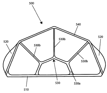
Figure 5 is a schematic of an exemplary embodiment of a golf club head
designed to
act, under impact load, as a bridge. As noted above, in Figure 5, face 510 is
not physically
connected to inertial support system 520.
Figure 6 is a schematic of an exemplary embodiment of a golf club head
designed to
act, under impact load, as a bridge. Like golf club head 500, face 610 is
connected to force
transfer system 630 and rear structure 640, but is not physically connected to
inertial support
system 620. Force transfer system 630 comprises eight component parts, inner
structures
630a and radial structures 630b.
In addition, force transfer system 630 is separated into a top portion and a
bottom
portion. The separation may occur at any point along the height of force
transfer system 630,
with the height of the top portion being equal to, less than, or greater than,
the height of the
bottom portion. Under impact load, golf club head 600 reacts the same as golf
club heads 100
through 500. In particular, force transfer system 630 produces the same effect
produced in
force transfer systems 130 through 530-that is, in connection with inertial
support system
620 (or, in an alternate embodiment, in connection with inertial support
system 620 and rear
structure 640), elongating rear structure 640, controlling the bending of face
610 (and thus
the deflection of face 610), and controlling the rate of deflection of face
610.
In alternate embodiments of golf club head 600, force transfer system 630 may
be
separated into a left portion and a right portion. The separation may occur at
any point along
the length of force transfer system 630, with the length of the left portion
being equal to, less
than, or greater than, the length of the right portion. In addition, force
transfer system 630
may be separated into more than two portions, with the height (or length) of
each portion
11
CA 02573449 2007-01-10
WO 2006/022615 PCT/US2004/023368
being equal to, less than, or greater than the height (or length) of any other
portion. In
addition, the separate portions of force transfer system 630 may not be
"mirror images" of
each other. In other words, the separate portions of force transfer system 630
may have
different structures. For example, in a force transfer system with a top
portion and a bottom
portion, the top portion may be structured similar to force transfer system
430 (in Figure 4)
and the bottom portion may be structured similar to force transfer system 230
(in Figure 2).
Also, the separate portions of force transfer system 630 may be "misaligned"
with one or
more of the separate portions in a different plane than one or more of the
other portions.
Figures 7a and 7b are schematics of an exemplary embodiment of a golf club
head
designed to act, under impact load, as a bridge. In golf club head 700, face
710 connects to
inertial support system 720 and force transfer system 730. In turn, rear
structure 740 is
connected to force transfer system 730 and face 710.
Unlike force transfer systems 130 through 630, force transfer system 730
comprises
the crown of golf club head 700. In particular, force transfer system 730 is a
crown of
varying thickness that acts as part of the bridge structure. For example, as
shown in Figure
7b, force transfer system 730 may have a single region, in which the thickness
varies from
the front of the region to the back of the region. Or, force transfer system
730 may have more
than one region, in which the thickness of each region varies in the same
manner or in
different manners. For example, in each region the thickness may vary from the
front of each
region to the back of each region. Or, in a first region, the thickness may
vary from the front
of that region to the back of that region, in a second region, the thickness
may vary from the
center of that region to the edges of that region, etc. Under impact load,
force transfer system
730 produces the same effect produced in force transfer systems 130 through
630-that is, in
connection with inertial support system 720 (or, in an alternate embodiment,
in connection
with inertial support system 720 and rear structure 740), elongating rear
structure 740,
controlling the bending of face 710 (and thus the deflection of face 710), and
controlling the
rate of deflection of face 710.
In an alternate embodiment of golf club head 700, force transfer system 730
comprises the sole of golf club head 700. In another alternate embodiment of
golf club head
700, force transfer system 730 comprises both the crown and the sole of golf
club head 700.
12
CA 02573449 2007-01-10
WO 2006/022615 PCT/US2004/023368
In another alternate embodiment of golf club head 700, force transfer system
730 may
comprise a part of the crown of golf club head 700, the remaining part of
force transfer
system configured in a manner similar to the force transfer systems shown in
Figures 1- 6.
Or, force transfer system 730 may comprise a part of the sole of golf club
head 700, the
remaining part of force transfer system configured in a manner similar to the
force transfer
systems shown in Figures 1- 6. Likewise, force transfer system 730 may
comprise a part of
the crown and a part of the sole of golf club head 700, the remaining part of
force transfer
system configured in a manner similar to the force transfer systems shown in
Figures 1- 6.
Figure 8 is a schematic of an exemplary embodiment of a golf club head
designed to
act, under impact load, as a bridge. In golf club head 800 (which is similar
in structure to golf
club head 100), a torsion control system, identified as cross-brace 850, is
connected to rear
structure 840 and force transfer system 830. Under off-center impact load,
cross-brace 850
provides torsional resistance to force transfer system 830. In other words, in
connection with
inertial support system 820, cross-brace 850 opposes the internal "rotation"
(relative to
inertial support system 820) of force transfer system 830 resulting from an
off-center impact
load. In addition, in an off-center impact load, approximately one-half (left
side or right side)
of cross-brace 850 is placed in a state of substantially pure axial
compression and
approximately one-half (right side or left side) is placed in a state of
substantially pure axial
tension.
In an alternate embodiment of golf club head 800, the mass of inertial support
system
820 is no less than 30% of the combined mass of face 810, force transfer
system 830, rear
structure 840 and torsion control system 850. Thus, in this alternate
embodiment of golf club
head 800, a large portion of the mass of golf club head 800 may be used to
optimize moment
of inertia values for golf club head 800.
Figure 9 is a schematic of an exemplary embodiment of a golf club head
designed to
act, under impact load, as a bridge. In golf club head 900 (which is similar
in structure to golf
club head 200), a torsion control system, identified as cross-brace 950, is
connected between
the various approximate intersections of rear structure 940, and/or inner
structure 930a,
and/or radial structure 930b, and/or face 910. Like cross-brace 850, cross-
brace 950 provides
torsional resistance to force transfer system 930. In other words, in
connection with inertial
13
CA 02573449 2007-01-10
WO 2006/022615 PCT/US2004/023368
support system 920, cross-brace 950 opposes the internal "rotation" (relative
to inertial
support system 920) of force transfer system 930 resulting from an off-center
impact load.
Figure 10 is a schematic of an exemplary embodiment of a golf club head
designed to
act, under impact load, as a bridge. In golf club head 1000 (which is similar
in structure to
golf club head 500), a torsion control system, identified as insert 1050, is
placed in the
"opening" between force transfer system 1030 and rear structure 1040 and/or in
the
"opening" between force transfer system 1030, rear structure 1040 and face
1010, and/or in
the "opening" between force transfer system 1030 and face 1010. As shown in
Figure 11a,
insert 1050 is a "cored out" structure that comprises two component parts, web
1052 and
flange 1054. In contrast, insert 1050 may be a solid structure (not shown). In
an alternate
embodiment, as shown in Figure 11b, insert 1050 may further comprise a cross-
brace, such
as cross-brace 1056. Insert 1050 may also comprise a flange, such as flange
1054, and a
cross-brace, such as cross-brace 1056. Insert 1050 may be composed of an
assembly of
multiple elements, the elements composed of metal, plastic or composite
materials. Insert
1050 may also be composed, in whole or in part, of foam.
In addition, web 1052 may have constant wall thicknesses, multiple wall
thicknesses,
varying wall thicknesses or profiled wall thicknesses. For example, the inner
edge of web
1052 (near inner structure 1030a) may be thicker than the outer edge of web
1052 (near rear
structure 1040 or inertial support system 1020). In another alternate
embodiment, the
thickness of web 1052 may mirror the thickness of radial structure 1030b. It
may also be
profiled to conform with the deformation of radial structure 1030b under
center impact
loading.
Like cross-braces 850 and 950, insert 1050 provides torsional resistance to
force
transfer system 1030. Thus, in connection with inertial support system 1020,
insert 1050
opposes the internal "rotation" (relative to inertial support system 1020) of
force transfer
system 1030 resulting from an off-center impact load.
In tuning performance of the golf club head, the torsion control system
(whether a
cross-brace, an insert, or some combination of both) may be positioned at any
point along the
height of the force transfer system. In addition, the torsion control system
may be positioned
at different points along the height of the force transfer system for each
"opening" in the golf
club head. Further, one or more "openings" in the golf club head may contain
more than one
14
CA 02573449 2007-01-10
WO 2006/022615 PCT/US2004/023368
component of the torsion control system or, in the alternative, contain no
component of the
torsion control system. A person of skill in the art understands that tuning
the torsion control
system "tunes" the rate of deflection of the face and, in turn, the impedance
match between
the face of the golf club head and the ball.
The geometry and/or material property and/or attachment method of the torsion
control system may also be varied to tune the performance of the golf club
head. The
performance tuning may occur at the time of manufacture, at the time of sale,
or "in the
field"-making the torsion control system re-configurable and/or replaceable.
These "sets"
of torsion control systems may be designed for the needs of a particular group
of golfers or
for the needs of a particular golfer.
In an alternate embodiment of each of the exemplary embodiments of golf club
heads, the golf club heads may further include a back, such as back 350 in
golf club head
300. Or, in further alternative embodiments of each of the golf club heads,
the back of the
golf club head may be the rear structure or the inertial support system. In
addition, the torsion
control system may form all (or part) of the sole or crown of the golf club
head. When
forming all (or part) of the sole or crown of the golf club head, the torsion
control system
may be composed (in whole or part) of a material that provides scuff
resistance for the golf
club head, such as a plastic, metal (for example, thin titanium) or composite
material (such as
a combination of metal and plastic).
In other alternate embodiments of each of the exemplary embodiments of golf
club
heads, the face may be convex in shape from crown to sole (for example, a
"roll") or convex
in shape from heel to toe (for example, a "bulge") or convex in shape from
crown to sole and
heel to toe (for example, a combination of a "roll" and a "bulge").
In a further alternate embodiment of each of the exemplary embodiments of golf
club
heads, the inertial support system further includes a hosel, such as hosel 450
in golf club
head 400. A hosel is a connection point on a golf club head to which a golf
club shaft is
attached. In addition, the golf club heads may include other "conventional"
design options,
such as offsets, face angles, loft angles or lie angles.
In still another embodiment of each of the exemplary embodiments of golf club
heads, the face, the inertial support system, the force transfer system, the
rear structure, and
the torsion control system may be integral units alone or in combination with
each other. For
CA 02573449 2007-01-10
WO 2006/022615 PCT/US2004/023368
example, the face and the force transfer system may be an integral unit, the
inertial support
system may be an integral unit, the face, the force transfer system and the
rear structure may
be an integral unit, or the torsion control system, the inertial support
system and the force
transfer system may be an integral unit.
In a further embodiment of each of the exemplary embodiments of golf club
heads,
the golf club head may further include a conventional crown, a conventional
sole, or a
conventional crown and a conventional sole. The term "conventional" is used
herein to
differentiate from the "crown of varying thickness" described in Figure 7. In
order to ensure
that a conventional crown or conventional sole do not negatively impact the
bridge-like
operation of the golf club heads described herein, the conventional crown or
conventional
sole may be composed of a thermoset elastomer, a thermoplastic elastomer, or
an
engineering resin. The thermoset elastomer, thermoplastic elastomer, or
engineering plastic
may be combined with fillers or fibers, such as glass or carbon, to form a
composite
structure. In addition, the conventional crown or conventional sole may be
transparent (in
whole or in part) or translucent (in whole or in part).
Although various exemplary embodiments of the invention have been disclosed,
it
should be apparent to those skilled in the art that various changes and
modifications can be
made which will achieve some of the advantages of the invention without
departing from the
true scope of the invention. These and other obvious modifications are
intended to be
covered by the appended claims.
16