Note: Descriptions are shown in the official language in which they were submitted.
CA 02573486 2007-01-09
WATER FILTRATION SYSTEM
RELATED APPLICATION
[0001] The present application is being filed as a non-provisional patent
application
claiming priority/benefit under 35 U.S.C. 119(e) from U.S. Provisional
Patent Application No.
60/757,579 filed on January 10, 2006.
FIELD
[0002] The invention relates generally to water filtration systems and, more
particularly,
to a water filtration system connected to a fal.icet.
BACKGROUND
[0003] Tap water often includes impurities such as minerals, chlorine,
particulates and
other contaminants that affect the taste, odor, appearance and health quality
of the water. To
remove such impurities, water filtration devices are becoming increasingly
utilized for filtering
tap water.
SUMMARY
[0004] In view of the above, a water filtration system is provided that
includes a faucet
assembly and a filtration assembly. The faucet assembly comprises a spout
assembly including a
first water outlet and a second water outlet; a first valve assembly for
comlecting to an unfiltered
{13CR0083 DOC;3} 1
CA 02573486 2007-01-09
Attorney Docket No. 27475/08868
Express Mailing No. EV757384678US
hot water supply and an unfiltered cold water supply and operable to control
delivery of
unfiltered water to the first water outlet of the spout assembly; and a second
valve assembly for
connecting to a filtered water outlet of the filtration assembly and operable
to control delivery of
filtered water to the second water outlet of the spout assembly. A waterway
between the first
valve assembly and the first water outlet is separate from a waterway between
the second valve
assembly and the second water outlet. Accordingly, there is no possibility of
cross
contamination between the unfiltered water and the filtered water. The
filtration assembly
comprises a filter assembly; a filter bracket or mounting assembly for
securing the filter
assembly to a support surface or structure; and a filter manifold assembly
including an unfiltered
water inlet for connecting to an unfiltered water supply and the filtered
water outlet for
conulecting to the second valve assembly.
[0005] Numerous advantages and features will become readily apparent from the
following detailed description of exeinplary embodiments, from the claims and
from the
accompanying drawings.
BRIEF DESCRIPTION OF THE DRAWINGS
[0006] The invention as well as embodiments and advantages thereof are
described
below in greater detail, by way of example, with reference to the drawings in
which:
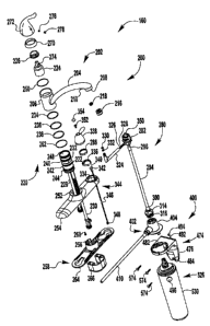
[0007] Figure 1 is an exploded perspective view of a water filtration system,
according to
an exemplary embodiment;
[0008] Figl.ire 2 is a front view of the water filtration systern of Figure 1;
[0009] Figure 3 is a right side view of the water filtration system of Figure
1;
[0010] Figure 4 is a cross-sectional view of an upper portion of a faucet
assenibly along
line A-A in Figure 2;
{ BCR0083.DOC;3 } 2
CA 02573486 2007-01-09
Attorney Docket No. 27475/08868
Express Mailing No. EV757384678US
[0011] Figure 5 is an exploded perspective view of a second valve assembly of
Figure 1;
[0012] Figure 6 is a perspective view of the second valve assembly of Figure
5;
[0013] Figure 7 is an exploded perspective view of a filter manifold assembly
of Figure
1;
[0014] Figure 8 is a cross-sectional view of the filter manifold assembly
along line B-B
of Figure 3;
[0015] Figure 9 is an exploded perspective view of a filter bracket assembly
of Figure 1;
[0016] Figure 10 is a rear view of the filter bracket assembly of Figure 9;
[0017] Figure 11 is a top plan view of the filter bracket assembly of Figure
9;
[0018] Figure 12 is a perspective view of a filter assembly of Figure 1;
[0019] Figure 13 is a side view of the filter assembly of Figure 12;
[0020] Figure 14 is a cross-sectional view of the filter assembly along line C-
C in Figure
13;
[0021] Figure 15 is a side view of a filter assembly, according to another
exemplary
embodiment;
[0022] Figure 16 is a cross-sectional view of the filter assembly along line D-
D of Figure
16;
[0023] Figure 17 is a cross-sectional view of the filter assembly along line E-
E of Figure
17; and
[0024] Figure 18 is a cross-sectional view of the asseinbled filtration
assembly of Figure
1.
{[3CR0083.DOC;3} 3
CA 02573486 2007-01-09
Attorney Docket No. 27475/08868
Express Mailing No. EV757384678US
DETAILED DESCRIPTION
[0025] While the general inventive concept is susceptible of embodiment in
many
different fonns, there are shown in the drawings and will be described herein
in detail specific
embodiments thereof with the understanding that the present disclosure is to
be considered as an
exemplification of the principles of the general inventive concept.
Accordingly, the general
inventive concept is not intended to be limited to the specific einbodiinents
illustrated herein.
[0026] Refen-ing to Fig. 1, a water filtration system 100 according to an
exemplary
embodiment is shown as an exploded view. A front view of the water filtration
system 100 is
illustrated in Fig. 2 and a right side view of the water filtration system 100
is illustrated in Fig. 3.
Fig. 4 sliows a cross-sectional view of an upper portion of the water
filtration system 100 along
line A-A of Fig. 2.
[0027] The water filtration system 100 includes a faucet assembly 200 and a
filtration
assembly 400. Preferably, but not necessarily, the filtration assembly 400 is
installed below the
faucet assembly 200. For example, the filtration assembly 400 may be installed
below a sink
deck (not sliown) on which the faucet assembly 200 is mounted.
[0028] The faucet assembly 200 includes a spout assembly 202, a first valve
assembly
220 and a second valve assembly 280.
[0029] The spout assembly 202 includes a spout 204 extending from a spout hub
206.
The spout 204 includes a spout tip 208, a filter tip 210, a spout tube 212 and
a filter tube 214.
The spout tube 212 and filter tube 214 can be seen in Fig. 4.
[0030] The spout tip 208 defines a first water outlet through which unfiltered
water may
flow out of the spout 204. The filter tip 210 defines a secoiid water outlet
tllrough which filtered
water may flow out of the spout 204. The spout tube 212 defines a first
waterway through the
{BCR0083.DOC;3} 4
CA 02573486 2007-01-09
Attorney Docket No. 27475/08868
Express Mailing No. EV757384678US
spout 204 and the filter tube 214 defines a second waterway tlu-ough the spout
204. Preferably,
but not necessarily, the filter tube 214 is disposed within the spout tube
212, as shown in Fig. 4.
In an alternative embodiment, a diverter assembly (not shown) is provided for
diverting at least
one of said unfiltered water and said filtered water from said spout assembly
202, for exainple, to
a side spray assembly (not shown).
[0031] Preferably, but not necessarily, an aerator asseinbly 216 is coimected
to the spout
tip 208 to introduce air into the unfiltered water flowing out of the spout
tip 208. The aerator
assembly 216 may reduce splashing, while increasing areas of coverage and
wetting efficiency.
[0032] Preferably, but not necessarily, a streain straightener 218 is
connected to the filter
tip 210 to straighten the flow of filtered water flowing out of the filter tip
210. For example,
filtered water flowing through the stream straightener 218 becomes laminar,
which provides a
pleasant look and feel. In one exemplary embodiment, a flow rate of the
filtered water
discharged througli the filter tip 210 is between .9 and 1.1 gallons per
minute, inclusive.
[0033] The first valve assembly 220 includes a first valve body 222, a first
valve 224 and
a first valve retaining nut 226. The first valve body 222 includes a hot water
supply tube 228, a
cold water supply tube 230 and a water outlet 232. The first valve body 222
includes a cavity
248 for receiving the first valve 224. The first valve 224 controls the amount
of hot water and
cold water to be mixed and delivered to the spout 204 via the water outlet 232
for output at the
spout tip 208. The first valve 224 may be a cartridge-type valve assembly.
[0034] The first valve body 222 containing the first valve 224 is disposed in
the spout
hub 206 of the spout assembly 202. O=rings 234, 236 and 238 are located in
grooves 240, 242
and 244, respectively, on an exterior of the first valve body 222 to fonn
seals between the
exterior surface of the first valve body 222 and an interior surface of the
spout liub 206. The first
{BCR0083.DOC;3} 5
CA 02573486 2007-01-09
Attorney Docket No. 27475/08868
Express Mailing No. EV757384678US
valve retaining nut 226 is connected (e.g., via threaded surfaces) to the
first valve body 222 to
secure the first valve 224 and the first valve body 222 within the spout hub
206. A bearing
washer 250 may be located between the spout hub 206 and the first valve
retaining nut 226.
[0035] The hot water supply tube 228 and the cold water supply tube 230 of the
first
valve body 222 are positioned through a first opening 252 of an escutcheon 254
and a first
opening 256 of a deck plate assembly 258. A valve body screw 260 may be used
to fasten the
first valve body 222 to the escutcheon 254. A bearing washer 262 may be
located between the
first valve body 222 and the escutcheori 254.
[0036] The escutcheon 254 and deck plate assembly 258 are mounted on a support
surface, for example, a sink deck (not shown). In this manner, the hot water
supply tube 228 and
the cold water supply tube 230 may pass tlirough an opening in the sinlc deck
for comiection to a
hot water supply source and a cold water supply source, respectively. The deck
plate assembly
258 includes a deck plate 264 located below the escutcheon 254 and a deck seal
(not shown)
disposed between the deck plate 264 and an upper surface of the sink deck. A
mounting/bracket
assembly 266 is disposed below the sink deck to secure the faucet assembly 200
relative to the
sink deck.
[0037] A dome 270 covers the first valve retaining nut 226 and connects (e.g.,
via
threaded surfaces) to the first valve body 222. A stem 2741ocated on a top
portion of the first
valve 224 projects tluough a central opening of the first valve retaining nut
226 and a central
opening of the dome 270 and into a lower portion of the handle 272. A handle
set screw 276 is
used to secure the handle 272 to the stem 274. Optionally, a plug button 278
may be used to
conceal the handle set screw 276 for cosmetic reasons.
( BCR0083. DOC;3 } 6
CA 02573486 2007-01-09
Attorney Docket No. 27475/08868
Express Mailing No. EV757384678US
[0038] Accordingly, a user can manipulate the handle 272 to actuate the first
valve 224.
For example, lifting the handle increases the flow rate of the water delivered
to the spout 204,
while lowering the handle decreases the flow rate of the water delivered to
the spout 204.
Additionally, lateral movement of the handle adjusts the temperature of the
water delivered to
the spout 204 by varying the amount of hot water and cold water being mixed.
[0039] As shown in Figs. 5 and 6, the second valve assembly 280 includes a
second
valve body 282, a second valve 284 and a second valve retaining nut 286. The
second valve
body 282 includes a water inlet barb 288 and a water outlet barb 290. The
second valve 284 is
disposed within a cavity 292 of the second valve body 282. The second valve
284 controls the
amount of filtered water delivered from the filtration assembly 400 to the
spout 204 for output at
the filter tip 210. The second valve 284 may be a cartridge-type valve
assembly.
[0040] The second valve assembly 280 further includes a tube 294 serving as a
waterway
between the filtration assembly 400 and the second valve 284. The tube 294 is
coimected at one
end to the water inlet barb 290, for example, via a crimp sleeve 296. The
other end of the tube
294 is coimected to a dome barb 298, for example, via a crimp sleeve 300.
[0041] The dome barb 298 serves as a filtered water outlet of the filtration
assembly 400.
The dome barb 298 has a hollow dome portion 302 that narrows into a hollow tip
portion 304.
On an exterior surface of the dome portion 302, an upper lip 306 and a lower
lip 308 fomi a
groove 310 for receiving an 0-ring 312. The 0-ring 312 forins a seal between
the dome barb
298 and an interior surface of a manifold body 404 of a filter manifold
assembly 402 (see Fig. 7),
as described below.
[0042] Furthennore, a dome barb retaining nut 314 secures the dome barb 298 to
the
filter manifold assembly 402. For example, a threaded portion 316 of the dome
barb retaining
(BCR0083.DOC;3 ) 7
CA 02573486 2007-01-09
Attoiney Docket No. 27475/08868
Express Mailing No. EV757384678US
nut 314 engages an upper threaded portion 436 of the manifold body 404 to
secure the dome
barb 298 to the manifold asseinbly 402. In this manner, the tip portion 304 of
the dome barb 298
extends through an upper central opening 318 of the dome barb retaining nut
314, so that the tip
portion 304 can be joined to the tube 294. The tip portion 304 of the dome
barb 298 defines an
outlet end 320 of the dome barb 298, while the dome portion 302 of the dome
barb 298 defines
an inlet end 322 of the dome barb 298.
[0043] Another tube 324 (see Fig. 1) is used to establish a waterway between
the second
valve 224 and the filter tube 214 in the spout 204. 0-rings 326 and 328 may be
used to fonn a
seal at the joint where the water outlet barb 288 of the second valve assembly
280 and the tube
324 are joined. 0-rings 330 and 332 maybe used to fonn a seal at the joint
where the tube 324
and the spout assembly 202 are joined.
[0044] The second valve body 282 containing the second valve 284 extends
through a
second opening 334 in the escutcheon 254. A spacer 336 may be used, for
example, to
accommodate the second valve retaining nut 286. Preferably, but not
necessarily, the spacer 336
includes a spacer opening 340 for accommodating a light-emitting diode (LED)
342 of an LED
assembly 344. In this manner, the spacer 336 provides a rigid stop for the
second valve retaining
nut 286, so that the second valve retaining nut 286 is not tightened against
the LED 342.
[0045] The LED assembly 344 includes the light-emitting diode 342 and a first
wiring
346. Preferably, but not necessarily, the first wiring 346 has a first
connector 348 at one end to
facilitate connection to another wiring. The light-emitting diode 342 may be
used to indicate that
a filter assembly 526 (see Fig. 12) should be replaced because, for example,
its filtering capacity
is spent.
{BCR0083.DOC;3} 8
CA 02573486 2007-01-09
Attoniey Docket No. 27475/08868
Express Mailing No. EV757384678US
[0046] A stem 350 located on a top portion of the second valve 284 projects
tlirough a
central opening of the second valve retaining nut 286 and a central opening of
the spacer 340 and
into a lower portion of the handle 338. A handle screw 352 is used to secure
the handle 338 to
the stem 350. Optionally, a handle cap 354 may be used to conceal the handle
screw 352 for
cosmetic reasons.
[0047] Accordingly, a user can manipulate the handle 338 to actuate the second
valve
284. For example, turning the handle clockwise increases the flow rate of the
filtered water
delivered to the spout 204, while turning the handle counterclockwise
decreases the flow rate of
the filtered water delivered to the spout 204. In another exemplary
embodiment, an actuator
(e.g., a button) is provided in lieu of the handle 338 to control delivery of
the filtered water to the
spout 204, wherein the flow rate of the filtered water may be fixed.
[0048] As described above, the faucet assembly 200 allows a user to control
delivery of
unfiltered water fiom a water supply source and filtered water from a
filtration assembly 400 to a
single spout asseinbly 202. The filtration assembly 400 shown in Figs. 1-3
will now be
described in more detail with reference to Figs. 7-14.
[0049] The filtration assembly 400 includes a filter manifold asseinbly 402, a
filter
bracket or mounting assembly 474 and a filter assenibly 526.
[0050] The filter manifold assembly 402 is shown as an exploded view in Fig. 7
and as a
cross-sectional view in Fig. 8. The filter manifold assembly 402 includes a
manifold body 404, a
water inlet barb 406 and a plunger 408. The filter manifold assembly 402
facilitates connection
of a water supply source (not shown), the filter assembly 526 and the second
valve assembly
280. The water supply source may be a separate water supply source or inay be
the
aforementioned cold water supply source.
( BCROOB3.D0C;3 } 9
CA 02573486 2007-01-09
Attorney Docket No. 27475/08868
Express Mailing No. EV757384678US
[0051] Unfiltered water is delivered from the water supply source to the water
inlet barb
406 of the filter manifold assembly 402 via a tube 410. The tube 410 may be
connected to the
water inlet barb 406 by a crimp sleeve 412.
[0052] The manifold body 404 includes a flat base 414 with a cylindrical
portion 416
formed thereon. The cylindrical portion 416 is hollow and has a cavity that
forms at least a first
inner portion 418, a second inner portion 420 and a third inner portion 422. A
lower ledge 424
separates the second inner portion 420 and the third inner portion 422. An
upper opening 426 is
fonned in the cylindrical portion 416 and a lower opening 428 is formed in the
flat base 414. A
tubular projection 430 extends from the cylindrical portion 416. The tubular
projection 430
fonns an outer side opening 432 and an inner side opening 434. The inner side
opening 434 is
formed where the tubular projection 430 and the cylindrical portion 416 meet
and forms a
waterway from the water inlet barb 406 to the second inner portion 420 of the
cylindrical portion
416 of the manifold body 404.
[0053] The upper opening 426 is for mounting the dome barb 298 to the filter
manifold
assembly 402. The lower opeiiing 428 is for inserting the filter assembly 526
therein, as
described below. The outer side opening 432 and the inner side opening 434 are
for mounting
the water inlet barb 406 and the plunger 408 therein, so as to control the
flow of unfiltered water
from the water supply source to the filtration assembly 400.
[0054] The upper tlu=eaded portion 436 of the cylindrical portion 416 of the
manifold
body 404 engages with the threaded portion 316 of the dome barb retaining nut
314 to secure the
dome barb 298 within the cylindrical portion 416 of the manifold body 404. In
particular, the
lower lip 308 of the dome barb 298 rests on an upper ledge 438 between the
first inner portion
418 and the second iimer portion 420, such that the 0-ring 3121ocated in the
groove 310 of the
{BCR0083.DOC;3 } 10
CA 02573486 2007-01-09
Attoniey Docket No. 27475/08868
Express Mailing No. EV757384678US
dome barb 298 is housed within the first inner portion 418 of the manifold
body 404. The dome
barb retaining nut 314 prevents the 0-ring 312 from exiting the first iimer
portion 418, thereby
maintaining the seal formed by the 0-ring 312. Preferably, but not
necessarily, the lower lip 308
of the dome barb 298 has a non-circular shape for fitting into the first inner
portion 418 having
the same non-circular shape. For example, a multi-lobular shape and, in
particular, a tri-lobular
shape, may be used as the non-circular shape.
[0055] The flat base 414 of the manifold body 404 is substantially circular.
The
circumference of a lower portion 440 of the flat base 414 is less than the
circumference of an
upper portion 442 of the flat base 414, so as to form a recessed lip 444
around the outer edge of
the flat base 414. A plurality of flanges 446 are disposed on the outer edge
of the lower portion
440 of the flat base 414. Each flange 446 has a tooth 448 thereon. The flanges
446 and teeth
448 are used to connect the filter manifold assembly 402 to the filter bracket
assembly 474, as
described below.
[0056] The water inlet barb 406 has a tlu-eaded portion 450 for engaging a
threaded
portion 452 of the tubular projection 430 of the manifold body 404.
Preferably, but not
necessarily, adhesive is applied to the threaded portion 450 of the water
inlet barb 406 before it
engages the tlu-eaded portion 452 of the tubular projection 430. Additionally,
an 0-ring 454 is
positioned on the water inlet barb 406 and adjacent to the threaded portion
450 of the water inlet
barb 406 to form a seal where the water inlet barb 406 and the tubular
projection 430 are joined,
[0057] A projection 456 is disposed in an interior cavity of the water inlet
barb 406 for
engaging one end 458 of a plunger spring 460. The other end 462 of the plunger
spring 460 is
inserted into a recessed end 464 of the plunger 408. In this mamler, the
plunger spring 460 urges
(BCROO83.DOC;3) 11
CA 02573486 2007-01-09
Attorrrey Doclcet No. 27475/08868
Express Mailing No. EV757384678US
the plunger 408 toward the second inner portion 420 of the cylindrical portion
416 of the
manifold body 404.
[0058] More particularly, the plunger spring 460 urges the plunger 408 into a
"closed"
position by urging the plunger 408 toward the inner side opening 434 of the
tubular projection
430, such that a plunger tip 466 protrudes through the inner side opening 434
and a smooth end
468 of the plunger 408 blocks the inner side opening 434. In this "closed"
position, water
flowing into the water inlet barb 406 and the tubular projection 430 cannot
enter the cylindrical
portion 416 of the manifold body 404. Additionally, an 0-ring 470 may be
positioned in a
groove 472 adjacent to the smooth end 468 of the plunger 408 to ensure a water-
tight seal
between the plunger 408 and the inner side opening 434. The plunger 408 is
configured to
reinain in the "closed" positiori when a filter is not present in the water
filtration system 100 and
to move to an "open" position when a properly configured filter is inserted in
the water filtration
system 100, as described below.
[0059] The filter bracket assembly 474 is shown as an exploded view in Fig. 9,
a rear
view in Fig. 10 and a top plan view in Fig. 11. -
[0060] The filter bracket assembly 474 includes a bracket body 476, a printed
circuit
board (PCB) 478 and a sliding door 480. The filter bracket assembly 474
provides a support for
the filter asseinbly 526 and the filter manifold assembly 402. In this manner,
the filter bracket
assembly 474 bears the weight of the filter assembly 526 and the filter
manifold assembly 402.
[0061) The bracket body 476 includes an upper portion 482 and a lower portion
484.
Preferably, but not necessarily, the upper portion 482 is perpendicular to the
lower portion 484.
The lower portion 484 has a plurality of mounting holes 486 for mounting the
bracket body 476
to a support surface or structure (e.g., a cabinet wall).
{BCR0083.DOC;3 } 12
CA 02573486 2007-01-09
Attorney Docket No. 27475/08868
Express Mailing No. EV757384678US
[0062] A rear surface of the lower portion 484 includes an area for mounting
the PCB
478 thereon. For example, a plurality of screws 488 are used to fasten the PCB
478 to the
bracket body 476. The PCB 478 includes metal contacts 490 and a second wiring
492.
Preferably, but not necessarily, the second wiring 492 has a second connector
494 at one end to
facilitate connection to the first connector 348 of the first wiring 346.
[0063] The metal contacts 490 make contact with a battery 496, which acts as a
power
source for the PCB 478 and the LED assembly 344. The second wiring 492
connects to the first
wiring 346 such tliat if the PCB 478 detennines (e.g., based on elapsed time,
gallons filtered,
etc.) that the filter assembly 526 needs to be replaced, the PCB 478 causes an
electric current to
flow to and illuminate the LED 342. In this manner, a user is provided with a
visual reminder to
replace the filter assembly 526.
[0064] The rear surface of the lower portion 484 also includes a plurality of
wiring
recesses 498 for holding and guiding the second wiring 492. Additionally, a
wiring post 500 is
provided to anchor the second wiring 492 so that a force (e.g., caused by
inadvertent contact) on
the second wiring 492 is distributed to the wiring post 500 and not only to
the point where the
second wiring 492 and the PCB 478 are joined.
[0065] A front surface of the lower portion 484 includes a door slot 502 for
receiving the
sliding door 480. The sliding door 480 includes a battery compartment 504 for
holding the
battery 496. Preferably, but not necessarily, the battery 496 is initially
attached (e.g., via
adhesive) to the filter asseinbly 526 (see Figs. 1, 2, 12 and 13) so that a
user can install/replace
the battery 496 at the time of installing/replacing the filter assembly 526.
In particular, the user
removes the battery 496 from the filter assembly 526 and inserts the battery
496 into the battery
compartment 504 of the sliding door 480. Alternatively, the battery 496 may be
integrated into
(dCR0083.DOC;3) 13
CA 02573486 2007-01-09
Attorney Docket No. 27475/08868
Express Mailing No. EV757384678US
the filter assembly 526 so that replacing the filter assembly 526 necessarily
includes replacing
the battery 496 without requiring additional effort on the part of the user.
[0066] Preferably, but not necessarily, the sliding door 480 may be readily
inserted into
and removed fi=om the door slot 502 by a user without using any tools. For
example, the sliding
door 480 may friction fit into the door slot 502 such that the sliding door
480 remains seated in
the door slot 502 until the user pulls it out. Fully inserting the sliding
door 480 into the door slot
502 causes the metal contacts 490 to contact the battery 496.
[0067] The upper portion 482 of the bracket body 476 includes an opening 506.
The
opening 506 includes an upper wall 508 and a lower wa11510 defining the
circumference of the
opening 506. A circumference of the upper wall 508 is generally greater than
the circumference
of the recessed lip 444 of the flat base 414 of the manifold body 404 but less
than the
circumference of the upper portion 442 of the flat base 414 of the manifold
body 404.
[0068] A plurality of notches 512 are foimed along the upper wall 508 of the
opening
506. The thiclcness of the upper wa11508 decreases in the notches 512.
Adjacent to the notches
512, the upper wall 508 extends out over the lower wall 510. A rib 514 is
fonned near a point
where the notch 512 abuts the upper wal1508. Preferably, but not necessarily,
the point where
the notch 512 abuts the upper wall 508 is sloped.
[0069] A plurality of ledges 516 project within the opening 506. Preferably,
but not
necessaiily, the ledges 516 are evenly spaced within the opening 506, that is
every 120 degrees.
Preferably, but not necessarily, the thickness of the ledges 516 is
approximately equal to the
height of the lower wal1510.
[0070] Each ledge 516 includes a raised side wall 518, a raised stop 520 and a
sloped
portion 522. The raised side wall 518 is thicker than the ledge 516 but does
not protrude into the
(BCaoo83.noC;3 } 14
CA 02573486 2007-01-09
Attorney Docket No. 27475/08868
Express Mailing No. EV757384678US
opening 506 as far as the ledge 516. The raised stop 520 is the same thickness
as the raised side
wal1518 but protrudes into the opening 506 further than the raised side wall
518. The raised
stop 520 is located at one end of the ledge 516 and the sloped portion 522 is
located on the
opposite end of the ledge 516. A flange 524 is positioned approximately in the
middle of the
raised side wall 518. The flange 524 is operable to move away from a center of
the opening 506
toward the upper wall 508 if sufficient force is applied to the flange 524.
The ledges 516 allow
the filter assembly 526 to interface with (and lock into) the filter bracket
assembly 474, as
described below.
[0071) A perspective view of the filter assembly 526 is shown in Fig. 12, a
side view of
the filter assembly 526 is shown in Fig. 13 and a cross-sectional view of the
filter assembly 526
is illustrated in Fig. 14.
[0072] Preferably, but not necessarily, the filter assembly 526 uses a carbon
filter and, in
particular, an activated charcoal filter. Activated charcoal is charcoal that
has been treated with
oxygen to open up a multitude of tiny pores between the carbon atoms. The use
of special
inantifacturing techniques results in higlily porous charcoals that have very
large surface areas.
The huge surface area of activated charcoal gives it numerous bonding sites.
When certain
chemicals pass next to the carbon surface, they attach to the surface and are
trapped. Once all of
the bonding sites are filled, an activated charcoal filter stops worlcing and
should be replaced.
[0073] The filter assembly 526 may be configured to operate across a
predetermined
range of water pressures. Preferably, but not necessarily, the filter assembly
526 operates within
a water pressure range of 20 to 125 pounds per square inch (psi). The filter
assembly 526 may
be configured to operate across a predetermined range of water temperatures.
Preferably, but not
necessarily, the filter assembly 526 operates within a water temperature range
of 35 to 100 F.
{ QCR0083.D0C;3 } 15
CA 02573486 2007-01-09
Attorney Docket No. 27475/08868
Express Mailing No. EV757384678US
The filter asseinbly 526 may be configured to have a predetennined usage
duration, after which
the filter assembly 526 should be replaced. In one exemplary embodiment, the
filter assembly
526 has a usage duration of six months.
[0074] The filter assembly 526 includes a tubular filter cartridge 528
disposed in a
tubular filter canister 530 sealed with a canister cap 532. Unfiltered water
enters the filter
canister 530 via inlet ports 534 and passes througli an inlet waterway 536.
Once inside the filter
canister 530, the unfiltered water fills a space 584 surrounding the filter
cartridge 528, passes
through the filter cartridge 528 (with various chemicals and impurities being
removed) and flows
radially inward to a central cavity 538 of the filter cartridge 528.
Accordingly, water in the
central cavity 538 of the filter cartridge 528, which is now filtered water,
may be discharged out
of the filter canister 530 through an outlet waterway 540 and out an outlet
port 542.
[0075] The filter cartridge 528 includes a filter cap 544, a filter bottom 546
and the
central cavity 538. The outlet watei-way 540 allows filtered water within the
central cavity 538
to flow through the filter cap 544 and out the outlet port 542 disposed in an
upper portion of the
canister cap 532.
[0076] The canister cap 532 includes a first raised portion 548, a second
raised portion
550, a lower connector 552, a lower lip 554, an upper lip 556, a lower shaft
portion 558, an upper
com-iector 560, a niiddle shaft portion 562 and an upper shaft portion 564.
The canister cap 532
is hollow such that the outlet waterway 540 runs through a central opening
therein and ends at
the outlet port 542 fonned in the upper shaft portion 564 of the canister cap
532.
[0077] Preferably, but not necessarily, the first raised portion 548 and the
second raised
portion 550 are circular. Preferably, but not necessarily, the circumference
of the first raised
portion 548 is greater than the circumference of the second raised portion
550. Preferably, but
{ BCR0083.DOC;3 } 16
CA 02573486 2007-01-09
Attorney Docket No. 27475/08868
Express Mailing No. EV757384678US
not necessarily, the height of the first raised portion 548 is less than the
height of the second
raised portion 550.
[0078] The lower comlector 552 of the canister cap 532 is formed on the second
raised
portion 550. The lower connector 552 has a non-circular shape. Preferably, but
not necessarily,
the lower connector 552 has a rnulti-lobular shape (e.g., the tri-lobular
shape illustrated in Fig.
12). Portions of the lower connector 552 extend over the second raised portion
550 to form
overhanging portions 566 (see Fig. 14).
[0079] The lower lip 554 and the upper lip 556 of the canister cap 532 are
formed above
the lower connector 552. Preferably, but not necessarily, the lower lip 554
and the upper lip 556
are circular. Preferably, but not necessarily, the lower lip 554 and the upper
lip 556 have the
same circumference. A groove is defined between the lower lip 554 and the
upper lip 556 for
receiving an 0-ring 568. The 0-ring 568 forms a seal between the filter
assembly 526 and the
filter manifold assembly 402 when the filter assembly 526 is mounted in the
water filtration
system 100, as described below.
[0080] The lower shaft portion 558 is formed above the upper lip 556.
Preferably, but
not necessarily, the lower shaft portion 558 is circular. Preferably, but not
necessarily, the
circumference of the lower shaft portion 558 is less than the circumference of
the upper lip 556.
[0081] The upper connector 560 of the canister cap 532 is fonned on the lower
shaft
portion 558. The upper connector 560 has a non-circular shape. Preferably, but
not necessarily,
the upper connector 560 has a multi-lobular shape (e.g., the tri-lobular shape
illustrated in Fig.
12). In one exemplary embodiment, the upper conriector 560 has a non-circular
shape formed
frorn a circular portioii and a projection extending from said circular
portion that allows the
iCiCR0083.DOC;3 } 17
CA 02573486 2007-01-09
Attorney Docket No. 27475/08868
Express Mailing No. EV757384678US
unfiltered water to flow into the tubular filter canister 530. Portions of the
upper coiuiector 560
extend over the lower shaft portion 558 to form overhanging portions 570 (see
Fig. 14).
[0082] The middle shaft portion 562 and the upper shaft portion 564 are formed
above
the upper connector 560. The upper shaft portion 564 includes the outlet port
542 for outputting
filtered water from the filter asseinbly 526. Preferably, but not necessarily,
the middle shaft
portion 562 and the upper shaft portion 564 are circular. Preferably, but not
necessarily, the
circumference of the middle shaft portion 562 is less than the circumference
of the lower shaft
portion 558. Preferably, but not necessarily, the circumference of the upper
shaft portion 564 is
less than the circumference of the lower shaft portion 558. Preferably, but
not necessarily, the
middle shaft portion 562 and the upper shaft portion 564 have the same
circumference. A
groove is defined between the middle shaft portion 562 and the upper shaft
portion 564 for
receiving an 0-ring 572. The O-ring 572 fonns a seal between the filter
assembly 526 and the
dome barb 298 (in the filter manifold assembly 402) when the filter assembly
526 is mounted in
the water filtration system 100, as described below.
[0083] The inlet ports 534 of the filter assembly 526 are disposed between the
0-ring 568
and the 0-ring 572 such that the 0-rings 568, 572 are operable to form seals
on both sides of the
inlet ports 534. Preferably, but not necessarily, the distance from a
centerline of the 0-ring 568
to a centerline of the 0-ring 572 is between 0.670 inches and 1.315 inches,
inclusive. In one
exemplary embodiment, the distance from the centerline of the 0-ring 568 to
the centerline of
the 0-ring 572 is 0.995 inches 0.005 inches. Preferably, but not
necessarily, the 0-ring 568
has an outer diaineter of between 0.981 inches and 1.060 inches, inclusive. In
one exemplary
embodiment, the 0-ring 568 has an (uncompressed) thiclcness of approximately
0.103 inches and
an outer diameter of approximately 1.031 inches. Preferably, but not
necessarily, the 0-ring 572
{ BCR0083.DOC;3 } 18
CA 02573486 2007-01-09
Attorney Docket No. 27475/08 868
Express Mailing No. EV757384678US
has an outer diameter of between 0.603 inches and 0.680 inches, inclusive. In
one exemplary
embodiment, the 0-ring 572 has an (uncompressed) thiclcness of approximately
0.103 inches and
an outer diameter of approximately 0.651 inches.
[0084] A filter assembly 600, according to anotlier exemplaty embodiment, may
be used
in the filtration assembly 400 and includes structure for protecting an
internal filter (e.g., filter
cartridge 528) of the filter assembly 600. A side view of the filter assembly
600 is shown in Fig.
15 and cross-sectional views of the filter assembly 600 are shown in Figs. 16-
17. Except as
noted herein, the filter asseinbly 600 is substantially the same as the filter
assembly 526
described above. Accordingly, those elements that are the same between the
filter assembly 526
(shown in Figs. 12-14) and the filter assembly 600 (shown in Figs. 15-17) have
like reference
numbers in the drawings and will not be further described in detail.
[0085] As in the case of the filter assembly 526, the filter assembly 600
includes a
tubular filter cartridge 528 disposed in a tubular filter canister 530 sealed
with a canister cap 532.
In the filter assembly 600, a mesh wrap 602 surrounds the filter cartridge 528
to strengthen the
filter cartridge 528 and protect it from damage, for example, during assembly,
transit, etc.
[0086] . Additionally, a plurality of vertical ribs 604 project from an inner
surface of the
filter canister 530. The ribs 604 may be formed integrally with the inner
surface of the filter
canister 530. As shown in Figs. 17-18, the ribs 604 surround the filter
cartridge 528 and its mesh
wrap 602 to limit or prohibit radial movement of the filter cartridge 528
within the filter canister
530, thereby further protecting the filter cartridge 528 from damage, for
example, during
assembly, transit, etc. Aside from these structural differences, the filter
assembly 600 functions
in the same maiuler as the filter assembly 526.
{ BCR0083. DOC;3 ) 19
CA 02573486 2007-01-09
Attorney Docket No. 27475/08868
Express Mailing No. EV757384678US
[0087] In further describing the exemplary embodiments, the filtration
assembly 400
(e.g., including the filter assembly 526) connects to the faucet assembly 200.
By way of
exainple, if the faucet assembly 200 is installed on a sink deck (not shown),
the filtration
assembly 400 may be installed below the sink deck (e.g., in a cabinet).
[0088] Fig. 18 shows an assembled filtration assembly 400. In asseinbling the
filtration
asseinbly 400, the filter manifold assembly 402 is connected to the filter
bracket assembly 474.
In particular, each flange 446 on the flat base 414 of the manifold body 404
is aligned with a
notch 512 in the upper wall 508 of the upper portion 482 of the bracket body
476, such that the
manifold body 404 rests on the upper portion 482 of the bracket body 476 above
the opening
506.
[0089] Then, by lowering the flanges 446 into the notches 512 and turning the
manifold
body 404 (e.g., countercloclcwise) the teeth 448 of the flanges 446 ride over
the ribs 514 on the
lower wall 510 of the opening 506 to connect the manifold body 404 to the
bracket body 476.
The ledges 516 prevent the manifold body 404 from further counterclockwise
rotation. Because
the upper wall 508 projects into the opening 506 above the teeth 448, the
manifold body 404
carmot be lifted from the bracket body 476 when the manifold body 404 and the
bracket body
476 are so connected. Additiorially, by virtue of the recessed lip 444, the
flat base 414 of the
manifold body 404 rests on the raised side walls 518 so that the filter
bracket assembly 474
supports the filter manifold assembly 402.
[0090] Accordingly, the dome barb 298 of the second valve assembly 280 may be
inserted into the upper opening 426 of the rnanifold body 404 and held therein
by the dome barb
retaining nut 314. In this mamier, the water inlet barb 406 of the filter
manifold assenibly 402
functions as an unfiltered water inlet of the filtration assembly 400 and the
doine barb 298
{ BCR0083. DOC;3 } 20
CA 02573486 2007-01-09
Attorney Docket No. 27475/08868
Express Mailing No. EV757384678US
functions as a filtered water outlet of the filtration assembly 400. The tube
410 connects the
water inlet barb 406 to a water supply source (not shown) and the tube 294
carries the filtered
water output at the dome barb 298 to the second valve 284 of the faucet
assembly 200.
[0091) Before or after connection of the filter manifold assembly 402 and the
filter
bracket assembly 474, the bracket body 476 is mounted to a support surface or
structure (e.g., a
wall of an under-the-sink cabinet). For example, mounting screws 574 (see Fig.
1) are inserted
through the mounting holes 486 to secure the bracket body 476 to the support
surface or
structure.
[0092] Prior to mounting the filter bracket assembly 474, the PCB 478 is
secured to the
rear surface of the lower portion 484 of the bracket body 476 aiid the second
wiring 492 is
arranged with respect to the wiring post 500 and wiring recesses 498, as
illustrated in Fig. 10.
[0093] The battery 496, wliich may initially be attached to an outer surface
of the filter
canister 530 (see Figs. 1, 2, 12 and 13), is placed in the battery compartment
504 of the sliding
door 480. The sliding door 480 is then inserted into the door slot 502 of the
bracket body 476 so
that the metal contacts 490 of the PCB 478 contact the battery 496. The second
coiu-iector 494 of
the second wiring 492 may be connected to the first connector 348 of the first
wiring 346 so that
the battery 496 powers and the PCB 478 controls the LED 342 of the LED
assembly 344.
[0094] With the filter manifold assembly 402 comiected to the filter bracket
assembly
474, the water supply source and the faucet assembly 200 via the second valve
284, the filter
assen7bly 526 can be installed. The shape and configuration of the canister
cap 532 allows the
filter assembly 526 to interface with the filter manifold assembly 402 and
"lock" into the filter
bracket assembly 474.
S BCR0083. DOC;3 } 21
CA 02573486 2007-01-09
Attorney Docket No. 27475/08868
Express Mailing No. EV757384678US
[0095] The second raised portion 550 of the canister cap 532 fits through the
opening 506
including the ledges 516 of the upper portion 482 of the bracket body 476. The
first raised
portion 548 of the candster cap 532, however, does not fit through the opening
506 including the
ledges 516. The lower connector 552 fits through the opening 506 including the
ledges 516 of
the bracket body 476 only if the filter canister 530 is properly oriented. For
example, if the
lower connector 552 has a tri-lobular shape as shown in Fig. 12, the lower
connector 552 will fit
tl-irough the opening 506 including the ledges 516 only when iuitersection
points 576 where
adjacent lobes 578 meet are oriented to pass through the spaces along the
opening 506 between
adjacent ledges 516.
[0096] Once the lower coiulector 552 is properly oriented, the filter canister
530 sliould
be inserted into the bracket body 476 so that an upper surface of the first
raised portion 548 of
the canister cap 532 contacts the lower surface of the ledges 516 of the upper
portion 482 of the
bracket body 476. In this case, the lower connector 552 should be disposed in
the opening 506
above the lower wall 510 such that no portion of the lower connector 552
overlaps any of the
ledges 516.
[0097] The raised stops 520 of the ledges 516 contact the lobes 578 of the
lower
connector 552 to prevent the filter canister 530 from significantly rotating
in a clockwise
direction. Rotating the filter canister 530 in a counterclockwise direction
causes a lower surface
of the lower coimector 552 to rotate along the ledges 516 so that the
intersection points 576 of
the lobes 578 depress the flanges 524 of the ledges 516 in order to rotate
past the flanges 524.
[0098] Once the intersection points 576 have passed the flanges 524, the
flanges 524
return to their original positions so as to resist clockwise rotation of the
filter canister 530 within
the opening 506 in the upper portion 482 of the bracket body 476.
Additionally, the raised stops
(BCR0083.DOC;3) 22
CA 02573486 2007-01-09
Attorney Docket No. 27475/08868
Express Mailing No. EV757384678US
520 of the ledges 516 contact the lobes 578 of the lower coimector 552 to
prevent further
counterclockwise rotation of the filter canister 530. Accordingly, the filter
canister 530 is
considered to be installed and in a "locked" position relative to the filter
bracket assembly 474.
[0099] To uninstall the filter assembly 526 from the filter bracket assembly
474, the filter
canister 530 must be rotated in a clockwise direction with sufficient force to
overcome the
resistance of the flanges 524 against the intersection points 576 of the lobes
578.
[00100] As the filter assembly 526 is being installed in the filter bracket
assembly 474, the
filter assembly 526 is also interfacing with the filter manifold assembly 402
coiuiected thereto
(see Fig. 15). In particular, those portions of the canister cap 532 of the
filter assembly 526 that
are disposed above the lower connector 552 are inserted into the filter
manifold assembly 402
(including the dome barb 298) as the filter assembly 526 is installed in the
filter bracket
assembly 474.
[00101] The lower ledge 424 between the second inner portion 420 and the third
inner
portion 422 located inside the cylindrical portion 416 of the manifold body
404 fonns a non-
circular (e.g., a multi-lobular and, in particular, a tri-lobular) opening
between the second imier
portion 420 and the third inner portion 422. Each of the upper shaft portion
564, the 0-ring 572,
the middle shaft portion 562, the upper connector 560 and the lower shaft
portion 558 fonned on
the canister cap 532 are capable of fitting through the non-circular opening
in the lower ledge
424. None of the upper lip 556, the 0-ring 568 and the lower lip 554 are
capable of fitting
through the non-circular opening in the lower ledge 424.
[00102] For the upper connector 560 to fit through the non-circular opening in
the lower
ledge 424, the intersection points 580 where adjacent lobes 582 of the upper
comlector 560 meet
must be oriented to correspond to the non-circular opening in the lower ledge
424. The
{BCR0083.DOC;3} 23
CA 02573486 2007-01-09
Attorney Docket No. 27475/08868
Express Mailing No. EV757384678US
intersection points 580 of the upper connector 560 are substantially aligned
with the intersection
points 576 of the lower connector 552. If the filter manifold assembly 402 is
connected to the
filter bracket assembly 474, as described above, then rotating the filter
canister 530 so that the
lower connector 552 will fit through the opening 506 and the ledges 516 in the
upper portion 482
of the bracket body 476 of the filter bracket assembly 474 will ensure that
the upper connector
560 is properly aligned to pass through the non-circular opening in the lower
ledge 424 of the
manifold body 404 of the filter manifold assembly 402. Otherwise, the upper
connector 560 will
not fit through the non-circular opening in the lower ledge 424.
[00103] Once the filter canister 530 is properly aligned and is lifted so that
the lower
comlector 552 passes tlirough the opening 506 aaid the ledges 516 in the upper
portion 482 of the
bracket body 476 of the filter bracket assembly 474, those portions of the
canister cap 532
located above the upper lip 556 pass through the non-circular opening in the
lower ledge 424.
The upper lip 556, the lower lip 554 and the 0-ring 568 disposed between the
upper Iip 556 and
the lower lip 554 become located in the third inner portion 422 of the
cylindrical portion 416 of
the manifold body 404, directly below the lower ledge 424. In this manner, the
upper lip 556,
the lower lip 554 and the 0-ring 568 form a seal between the filter assembly
526 and the filter
manifold assembly 402 below the inlet ports 534 of the upper comiector 560.
[00104] The upper shaft portion 564, the middle shaft portion 562 and the 0-
ring 572
disposed between the upper shaft portion 564 and the middle shaft portion 562
pass tlirough an
inlet end 322 of the dome barb 298 and become disposed inside a hollow dome
portioii 302 of
the dome barb 298, which is held in the first in.ner portion 418 of the
cylindrical portion 416 of
the manifold body 404 by the dome barb retaining nut 314. In this manner, the
upper shaft
portion 564, the middle shaft portion 562 and the 0-ring 572 form a seal
between the filter
{BCR0083.DOC;3} 24
CA 02573486 2007-01-09
Attorney Docket No. 27475/08868
Express Mailing No. EV757384678US
assembly 526 and the filter manifold asseinbly 402 (housing the dome barb 298)
above the inlet
ports 534 of the upper connector 560.
[00105] As the filter canister 530 is installed, the upper connector 560
beconies located in
the second inner portion 420 of the cylindrical portion 416 of the manifold
body 404.
Additionally, at least a portion of the lower shaft portion 558 of the
canister cap 532 becomes
aligned with the lower ledge 424 so that the filter canister 530 can be
rotated with respect to the
lower ledge 424 with the lower shaft portion 558 capable of rotating within
the non-circular
opening in the lower ledge 424.
[00106] Accordingly, wllen the lower connector 552 of the canister cap 532 is
rotated
counterclockwise to install the filter asseinbly 526 into the "locked"
position relative to the filter
bracket assembly 474, the upper connector 560 also rotates counterclockwise
within the second
iimer portion 420 of the cylindrical portion 416 of the manifold body 404.
Preferably, but not
necessarily, a lower surface of the upper connector 560 rests on an upper
surface of the lower
ledge 424 after the filter canister 530 is rotated counterclockwise,
Preferably, but not
necessarily, a lower surface of the dome barb 298 at the inlet end 322 rests
on an upper surface
of the upper comiector 560.
[00107] The upper connector 560 rotates counterclockwise within the second
inner portion
420 of the cylindrical portion 416 of the manifold body 404 until the raised
stops 520 of the
ledges 516 of the bracket body 476 halt rotation of the lower comiector 552.
Accordingly, when
the filter canister 530 has been installed into the "locked" position in the
filter bracket asseinbly
474, one of the intersection points 580 of the lobes 582 of the upper
connector 560 contacts the
plunger tip 466 projecting through the iimer side opening 434 of the tubular
projection 430 of the
inanifold body 404.
{ [3CR0083.DOC;3 } 25
CA 02573486 2007-01-09
Attorney Docket No. 27475/08868
Express Mailing No. EV757384678US
[00108] By contacting the plunger tip 466, the upper connector 560 causes the
plunger
spring 460 to compress and the plunger 408 to move away from the inner side
opening 434.
Consequently, the smooth end 468 of the plunger 408 no longer blocks the inner
side opening
434 of the tubular projection 430 of the manifold body 404. In this "open"
position, water
flowing in through the water inlet barb 406 and into the tubular projection
430 can enter the
cylindrical portion 416 of the manifold body 404. In particular, unfiltered
water from the water
supply source can flow through the inner side opening 434 of the tubular
projection 430 of the
manifold body 404 and into the second inner portion 420 of the cylindrical
portion 416 of the
manifold body 404 where the upper connector 560 is located. The 0-ring 568
forms a seal
below the second inner portion 420 and the 0-ring 572 forms a seal above the
second inner
portion 420 to prevent the unfiltered water from leaking out of the second
inner portion 420.
[00109] The unfiltered water in the second inner portion 420 surrounds the
upper
coimector 560 in the second iimer portion 420 and enters the filter assembly
526 tlzrough the inlet
ports 534 on the upper connector 560. The unfiltered water then flows through
the inlet
waterway 536 and into the space 584 surrounding the filter cartridge 528. The
unfiltered water
then passes through the filter cartridge 528 which causes various chemicals
and impurities to be
reinoved from the water. Accordingly, as the unfiltered water flows through
the filter cartridge
528 it becomes filtered water. As the water is filtered, it flows into the
central cavity 538 of the
filter cartridge 528. The filtered water may be discharged from the central
cavity 538 of the filter
cartridge 528 through an outlet waterway 540 and out an outlet port 542 for
delivery to the faucet
assembly 200, for example, in response to a user manipulating the handle 338.
[00110] When the lower connector 552 of the canister cap 532 is rotated
clockwise to
uninstall the filter assembly 526 (e.g., to replace a spent filter asseinbly
526), the upper
(BCR0083.DOC;3 ) 26
CA 02573486 2007-01-09
Attorney Docket No. 27475/08868
Express Mailing No. EV757384678US
connector 560 rotates clockwise within the second inner portion 420 of the
cylindrical portion
416 of the manifold body 404. Because of this clockwise rotation of the upper
connector 560,
none of the intersection points 580 of the lobes 582 of the upper connector
560 contact the
plunger tip 466.
[00111] With no intersection points 580 contacting the plunger tip 466, the
plunger spring
460 extends to urge the plunger tip 466 further through the inner side opening
434 of the tubular
projection 430 of the manifold body 404 until the smooth end 468 of the
plunger 408 blocks the
inner side opening 434. As a result, when the filter canister 530 is moved
into the "unlocked"
position in the filter bracket assembly 474, unfiltered water is prevented
from flowing into the
cylindrical portion 416 of the rnanifold body 404. Accordingly, the flow of
unfiltered water
through the water filtration system 100 requires the presence of a properly
configured filter
assernbly 526 arrd that the filter assembly 526 be properly installed.
[00112] In the water filtration system 100, according to the exemplary
embodiments set
forth above, separate valve assemblies allow a user to selectively obtain
either filtered or
unfiltered water at the same spout 204 of the faucet assembly 200. For
example, filtered water
may be selected for drinking or cooking, while unfiltered water may be
selected for cleaning.
Additionally, both filtered and unfiltered water may flow from the spout at
the sanie time.
[00113] The above description of specific embodiments has been given by way of
example. From the disclosure given, those skilled in the art will not only
understand the general
inventive concept and its attendant advantages, but will also find apparent
various changes and
rnodifrcations to the structures and methods disclosed. It is sought,
therefore, to cover all such
changes and modifications as fall within the spirit and scope of the general
inventive concept, as
defined by the appended claims, and equivalents thereof.
(BCR0083.DOC;3 ) 27