Note: Descriptions are shown in the official language in which they were submitted.
CA 02573488 2007-01-08
1 Thorpe North & Western, LLP
Atty. Docket No. 01198--25566.NP
Express Mail No.
PIVOTING HANDHELD FOOD PREPARATION APPLIANCE
AND ASSOCIATED METHOD
PRIORITY CLAIM
Priority of United States Provisional Patent Application Serial No.
60/757,738,
filed on January 9, 2006, is claimed; and is herein incorporated by reference.
FIELD OF THE INVENTION
The present invention relates generally to handheld appliances and associated
methods for selectively gripping and operating these appliances.
BACKGROUND OF THE INVENTION
Handheld appliances, such as hand mixers and immersion blenders can be held
in one hand and process food ingredients with a variety of implements, such as
mixing beaters, whisks, or blades. Such handheld food preparation appliances
generally have either a 90 degree handle-to-implement orientation (hand
mixer), or a
vertically linear handle-to-implement orientation (immersion blender).
A hand mixer with a 90 degree orientation configuration has implements that
are substantially perpendicular to the alignment of the handle. This type of
handheld
kitchen appliance is convenient for preparing food ingredients in a bowl where
the
appliance can be held above the bowl with the processing implements extending
away
from the handle and into the bowl, and the handle extending parallel to the
horizontal
plane of the opening of the bowl. The 90 degree orientation of the handle with
respect to the implements provides a comfortable, ergonomic position for the
user's
hand to hold the handheld kitchen appliance when working with food in a bowl
on a
countertop surface. However, this 90 degree orientation does not generally
accommodate preparing foods that are in a narrow and/or deep container such as
a
drinking glass since the substantially horizontal handle prevents the
appliance from
being lowered into the narrow container so that the implement can reach the
bottom
inner surface of the container and effectively process ingredients therein.
The processing implements of an immersion blender are oriented at
approximately 0 or 180 degrees to the handle. Thus, the implements of this
type of
appliance extend away from the handle along a common longitudinal axis, or "in-
line" with the handle. This type of handheld kitchen appliance is convenient
for
CA 02573488 2007-01-08
L Thorpe North & Western, LLP
Atty. Docket No. 0 1 198--25566.NP
Express Mail No.
mixing food ingredients in smaller containers, such as mugs or cups. The in-
line
orientation of the handle with respect to the implements provide for a
comfortable,
ergonomic position for the hand to hold the handheld kitchen appliance when
working
in a relatively perpendicular orientation with respect to a countertop
surface.
Some kitchen appliances can switch between an in-line orientation and a 90
degree orientation. For example, see the GizmoTM Twist BlenderTM by Black and
Decker. However, these appliances have only a single activation switch that
can be
difficult to reach and awkward to maneuver in either or both orientations.
SUMMARY OF THE INVENTION
It has been recognized that it would be advantageous to provide a handheld
appliance or handheld food preparation appliance with both a beater or mixer
configuration (horizontal handle) and a plunge mixer configuration (vertical
handle).
In addition, it has been recognized that it would be advantageous to provide
such an
appliance with two switches, each associated with a different configuration of
the
appliance to facilitate comfortable or ergonomic use.
Accordingly, the present invention provides a handheld appliance comprising
a housing including two housing sections pivotally coupled together and having
two
interconnected orientation configurations with respect to one another. The
handheld
appliance also comprises a motor carried by the housing, and two separate
switches
associated with the housing and operably coupled to the motor. Each switch is
operable with a different orientation configuration of the sections.
In one aspect, a handheld food preparation appliance is provided. The
handheld food preparation appliance includes a housing with a handle and a
chuck
pivotally coupled together and having two interconnected orientation
configurations
with respect to one another. One of the orientation configurations is an
aligned
configuration in which a longitudinal axis of the handle is substantially
aligned with a
longitudinal axis of the chuck. Another orientation configuration is a
transverse
configuration in which the longitudinal axis of the handle is transverse to
the
longitudinal axis of the chuck. In both configurations the handle is
configured to be
gripped and the chuck is configured to support at least one rotational
element. The
handheld food preparation appliance also includes a motor carried by the
housing, and
two separate switches associated with the housing. Both switches are operably
CA 02573488 2007-01-08
3 Thorpe North & Western, LLP
Atty. Docket No. 01198--25566.NP
Express Mail No.
coupled to the motor and each switch is operable with a different orientation
configuration of the handle and chuck.
In another aspect, a method of selectively preparing food ingredients is
provided. The method includes selecting one of at least two configurations of
a food
preparation appliance. One configuration is an aligned configuration in which
a
longitudinal axis of a handle is substantially aligned with a longitudinal
axis of a
chuck. Another configuration is a transverse configuration in which the
longitudinal
axis of the handle is transverse to the longitudinal axis of the chuck. The
method
includes orienting the food preparation appliance in a desired configuration,
gripping
the appliance in a manner associated with the desired configuration, and
positioning a
rotational element extending from a chuck of the food preparation appliance
into a
container having ingredients therein. The method further comprises activating
one of
two separate switches associated with the desired configuration of the food
preparation appliance to operate a motor of the appliance coupled to the
rotational
element, and deactivating a switch to disengage the motor.
There has thus been outlined, rather broadly, various features of the
invention
so that the detailed description thereof that follows may be better
understood, and so
that the present contribution to the art may be better appreciated. Other
features of the
present invention will become clearer from the following detailed description
of the
invention, taken with the accompanying claims, or may be learned by the
practice of
the invention.
BRIEF DESCRIPTION OF THE DRAWINGS
FIG. 1 is a side view of a handheld appliance in accordance with an
embodiment of the present invention, shown with the appliance in a transverse
orientation configuration;
FIG. 2 is a side view of the handheld appliance of FIG. 1, shown with the
appliance in an aligned orientation configuration;
FIG. 3 is cross section view of the handheld appliance of FIG. 1;
FIG. 4 is a perspective view of the handheld appliance of FIG. 1;
FIG. 5 is a bottom view the handheld appliance of FIG. 1;
FIG. 6 is a side view of a handheld food preparation appliance in accordance
with one embodiment of the present invention, shown with the handle and chuck
in a
CA 02573488 2007-01-08
4 Thorpe North & Western, LLP
Atty. Docket No. 01 198--25566.NP
Express Mail No.
transverse orientation configuration with respect to each other, and shown
with a
beater attachment;
FIG. 7 is a side view of the handheld food preparation appliance of FIG. 6,
shown with the handle and chuck in an aligned orientation configuration with
respect
to each other, and shown with a plunge mixer attachment;
FIG. 8 is a side cross section view of the handheld food preparation appliance
of FIG. 6;
FIG. 9 is a perspective view of the handheld food preparation appliance of
FIG. 6, shown with the handle and chuck in an aligned orientation
configuration with
respect to each other, and shown with a chopper attachment;
FIG. 10 is a cross section view of the handheld food preparation appliance of
FIG. 9;
FIG. 11 is a perspective view of a handheld food preparation appliance in
accordance with another embodiment of the present invention, shown with the
handle
and the chuck in a transverse orientation configuration with respect to each
other, and
shown with a beater attachment;
FIG. 12 is a perspective view of the handheld food preparation appliance of
FIG. 11, shown with the handle and chuck in an aligned orientation
configuration
with respect to each other, and shown with a plunge mixer attachment;
FIG. 13 is a cross section view of the handheld food preparation appliance of
FIG. 11;
FIG. 14 is a cross section view of the handheld food preparation appliance of
FIG. 12; and
FIG. 15 is a bottom view of the handheld food preparation appliance of FIG.
11.
DETAILED DESCRIPTION
Reference will now be made to the exemplary embodiments illustrated in the
drawings, and specific language will be used herein to describe the same. It
will
nevertheless be understood that no limitation of the scope of the invention is
thereby
intended. Alterations and further modifications of the inventive features
illustrated
herein, and additional applications of the principles of the inventions as
illustrated
CA 02573488 2007-01-08
Thorpe North & Western, LLP
Atty. Docket No. 0 1 198--25566.NP
Express Mail No.
herein, which would occur to one skilled in the relevant art and having
possession of
this disclosure, are to be considered within the scope of the invention.
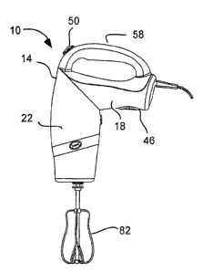
As illustrated in FIGs. 1-5, a handheld appliance, indicated generally at 10,
is
shown in accordance with an exemplary embodiment of the present invention.
Specifically, the appliance 10 is configured as a household food preparation
appliance, such as a combination hand mixer and immersion blender.
The handheld appliance 10 has a housing 14 with two housing sections, such
as a handle 18 and a chuck 22, pivotally coupled together. The handle can be
configured to be grasped in a user's hand. The chuck can be configured to
receive a
rotational element. The housing 14 or housing sections can be formed of
plastic and
can be a hollow shell. The housing sections or the handle 18 and chuck 22 can
be
pivotally coupled together at a joint 26. The housing section can pivot
between two
interconnected orientation configurations with respect to one another. The
configurations can include 1) an aligned configuration, as shown in FIG. 2,
and 2) a
transverse configuration, as shown in FIGs. 1, 3 and 4. In the alignment
configuration
(FIG. 2), a longitudinal axis 30 of the handle 18 is substantially aligned
with a
longitudinal axis 34 of the chuck 22. In the transverse configuration (FIGs. 1
and 3),
the longitudinal axis 30 of the handle 18 is transverse to the longitudinal
axis 34 of the
chuck 22. The longitudinal axis 30 of the handle 18 can extend along a length
of the
handle, or through openings in the user's hand when griping the handle. The
longitudinal axis 34 of the chuck 22 can be parallel with a rotational axis as
discussed
below.
The two housing sections can be coupled together in a variety of fashions. For
example, the handle can have a substantially annular track or groove or
channel while
the chuck can have one or more protrusions that extend into the track and move
in the
track as the handle and chuck twist. Alternatively, the housing sections can
be
coupled together by a fastener, such as a screw or bolt that also acts as an
axle about
which the housing sections can pivot with respect to one another.
Alternatively, the
housing sections can be coupled together by a ball and socket joint, a
substantial ball
and socket joint, or a dovetail joint. It is understood that the two housing
sections can
form a sequence of different angles with respect to each other between the two
interconnected orientation configurations.
CA 02573488 2007-01-08
b Thorpe North & Western, LLP
Atty. Docket No. 01198--25566.NP
Express Mail No.
A motor 38 (FIG. 3) can be carried by the housing 14, such as by being
disposed in the chuck 22. It is of course understood that the motor could be
disposed
in the handle. The motor 38 can be an electric motor powered by an electric
cord
plugged into a standard outlet, and extending through the handle.
Alternatively, the
motor can be powered by a battery carried by the housing, such as in the
housing.
The motor can have an output shaft or coupling 42 (FIG. 5) disposed on a
distal end
of the chuck to receive a rotational element. The output shaft can extend
directly to
the motor, as shown in FIG. 3, or can have a gear mechanism, as shown in FIG.
13.
As described above, the longitudinal axis 34 of the chuck can be parallel with
the
rotational axis of the motor or output shaft. The motor 38 can be coupled to
various
rotational implements, including food processing implements such as blenders,
whisks, beaters, blades and stirring rods.
Two separate switches 46 and 50 are associated with the housing 14 and
operatively coupled to the motor 38. The switches can be electrically coupled
between the motor and a power source, such as the electrical cord or a
battery. Each
switch is operable with a different orientation configuration of the housing
sections.
For example, one switch 50 can be operable in the transverse orientation, as
shown in
FIG. 1, while another switch 46can be operable in the aligned configuration,
as shown
in FIG. 2. In addition, the switches can be located at different locations on
the
housing or handle to correspond to convenient locations of the user's fingers
when
grasping the housing or handle in the different orientation configurations. In
one
aspect, the switches 46 and 50 can be electrical toggle or pulse switches that
turn the
motor 38 on and off. In another aspect, the switches 46 and 50 can be variable
resistance switches to control the speed of the motor at preset locations, or
steps.
Additional types of switches, as known in the art can also be used.
In addition, the handheld appliance 10 can include a switch selector 54 (FIG.
3) associated with the housing 14 and operable to engage one switch 46 or 50
and
disengage another switch 46 or 50 based on the orientation configuration.
Thus, the
switch selector 54 can be electrically coupled to the switches 46 and 50, such
as
between the power source and the switches. The switch selector 54 can toggle
back
and forth, selectively directing electricity to one of the two switches. The
switch
selector 54 may be operably disposed to engage the switches 46 and 50 as the
two
housing sections pivot. Each of the two switches can be selectively
deactivated by the
CA 02573488 2007-01-08
/ Thorpe North & Western, LLP
Atty. Docket No. 01 198--25566.NP
Express Mail No.
switch selector 54 depending on the orientation of the two housing sections
with
respect to one another. The switch selector can be disposed at the joint such
that
pivoting of the two housing sections operates the switch selector to
selectively allow
operation of the switches only in a respective designated interconnected
orientation
configuration. For example, the switch selector can be a toggle switch or the
like
coupled to one housing section, such as the handle, while a portion of the
other
housing section, such as the chuck, engages the toggle switch as the housing
sections
pivot.
The switch selector is operably disposed to engage the switches as the handle
and the chuck pivot. The switch selector can be disposed at a junction between
the
handle and the chuck, so that twisting the housing engages the switch selector
automatically. For example, the switch selector can be a switch mounted on one
section of the housing with another section of the housing engaging the switch
as the
two housing sections pivot with respect to one another. Thus, by pivoting the
handle
and chuck with respect to each other, a user automatically designates an
operable
switch for the orientation of the housing that is selected.
It will be appreciated that the switch selector is one example of means for
selectively engaging the switches. Alternatively, electrical contacts could be
located
at the joint to selectively align. The switch selector could also be a
magnetic switch
operated my magnets located at the joint.
The handle 18 can include two grip portions, such as a horizontal or
transverse
grip 58 that can be griped by the user in the transverse configuration and a
vertical
grip 62 that can be griped by the user in the aligned configuration. The
transverse
grip 58 can be an extension of the handle 18. In this sense, the transverse
grip 58 is
separate from the vertical grip 62 and can form a loop therewith, as shown in
FIGs. 1
and 2. Alternatively, the vertical grip and the transverse grip can be
integral with one
another, as shown in FIGs. 11 and 12.
The switches 46 and 50 are disposed on opposite sides of the housing 14 or
handle 18, as shown in FIGs. 1 and 2. Alternatively, the switches may both be
disposed on substantially the same side of the housing as shown in FIGs. 11
and 12.
In one aspect, the switches 46 and 50 can both be located on the handle 18.
One
switch 46 can be disposed on a proximal end of the handle 18, or vertical grip
62, so
that it is disposed near a top of the housing in the aligned configuration to
be engaged
CA 02573488 2007-01-08
tS Thorpe North & Western, LLP
Atty. Docket No. 01198--25566.NP
Express Mail No.
by a user's thumb. Another switch 50 can be disposed intermediate the housing
14,
such as on a distal end of the handle 18 or on the horizontal grip 58 to be
engaged by
a user's thumb in the transverse configuration.
Alternatively, the switches can be disposed on the same side of the handle, as
shown in FIGs. 11 and 12.
Referring to FIGs. 6-10, the handheld appliance 10 is shown configured as a
handheld food preparation appliance with various exemplary rotational
elements. The
chuck 22 can have distal end or an implement attachment end to receive the
rotational
element or implement, and which includes the coupling 42 (Fig. 3) from the
motor.
Thus, the end of the chuck can form a portion of an attachment, socket or
connection.
A rotational food processing implement can be removably attached to the
implement
attachment end.
The rotational element can be removably coupled to the implement
attachment end of the chuck. The rotational element can be engaged by the
motor or
coupling 42 when the element is coupled to the implement attachment end of the
chuck. The chuck and/or rotational element can include means for retaining or
securing the rotational element to the chuck. For example, a C-shaped bias
member
or spring 66 (FIG. 3) can be disposed in or carried by the chuck 22to secure
the
rotational element to the chuck. One or more hooks or barbs 70 (FIGs. 4 and 5)
can
extend from the bias member and can protrude from the chuck or implement
attachment end to engage and retain the rotational element. In addition, one
or more
buttons 74 can extend from the bias member and can protrude from the chuck so
that
pushing the buttons 74 causes the hooks or barbs to retract and release the
rotational
element. The bias nature of the bias member retains the barbs and buttons
outward.
Alternatively, the C-shaped bias member can be two parts, or two buttons, on
opposite
sides of the housing.
The rotational element can include a speed optimizing transmission or gear
box 78 (Fig. 8) having gears to modify the power from the motor and control
the
speed of the rotational element.
A variety of food processing implements can be used as the rotational element
that can be removably coupled to the implement attachment end of the chuck.
For
example, the rotational element can be selected from the group consisting of
blenders,
whisks, beaters, blades and stirring rods. In one embodiment, the rotational
element
CA 02573488 2007-01-08
Thorpe North & Western, LLP
Atty. Docket No. 01198--25566.NP
Express Mail No.
can be a mixer with a beater(s) 82 as shown in FIG. 6. or a pair of beaters
84, as
shown in FIG. 11. Alternatively, the beaters could be whisks or the like as
known in
the art. The beater(s) 82 can be coupled to the transmission or gear box 78.
Alternatively, the beaters can be coupled directly to the coupler. In another
aspect,
the rotational element can be a plunge blender 88, as shown in FIG. 7, with a
horizontally rotating blade at the bottom end. In another aspect, the
rotational
element can be a food processor 92, as shown in FIG. 10. The food processor 92
can
include a container or enclosure and one or more rotating blades to chop food
in the
enclosure. Other implements commonly found on handheld kitchen appliances can
also be integrated with the present invention.
Each of the various rotational elements can have a different gear transmission
to modify the power from the motor. For example, a stick or plunge blender 88,
as
shown in FIG. 7, can have no reduction and produce a knife speed of
approximately
11,000 rpm. Similarly, a bladed food processor attachment 92, as shown in FIG.
10,
can have a 5:1 reduction transmission and produce a knife speed of 2,200 to
1,100
rpm in 5 steps using a variable resistance switch for speed control, as
described above.
Additionally, a beater 82, as shown in FIG. 6, can have a 10:1 reduction
transmission
and produce a beater speed of 1,100 to 550 rpm in 5 steps using a variable
resistance
switch for speed control, as described above. Other gear reducing, speed
optimizing
transmissions, as known in the art, can be combined with attachable
implements.
Referring to FIGs. 6 and 8, the handheld appliance 10 can be configured as a
household food preparation appliance, namely a handheld mixer, with the handle
18
and chuck 22 configured in the transverse configuration and a beater 82 or
beater
attachment coupled to the chuck. In use, the handle 18 can be horizontal with
the
chuck 22 and beater 82 vertical; and the user can grasp the horizontal grip 58
and
engage the switch 50 thereon with the his or her thumb to operate the beaters.
The
switch selector 54 in the transverse orientation directs power to the switch
50 or
electrically couples the switch 50 to the power source. In addition, the
switch selector
54 terminates the electrical connection between the other switch 46 and the
power
source. Thus, the other switch 46 is prevented from operating the motor for
safety.
As described above, the switch 50 can have variable resistance to also control
the
speed of the motor.
CA 02573488 2007-01-08
i V Thorpe North & Western, LLP
Atty. Docket No. 01198--25566.NP
Express Mail No.
Referring to FIG. 7, the handheld appliance 10 can be configured as a
household food preparation appliance, namely a plunge mixer, with the handle
18 and
chuck 22 configured in the aligned configuration and a plunge mixer 88 coupled
to
the chuck. In use, the handle 18 can be vertical and aligned with the chuck 22
and
plunge mixer 88 which are also vertical; and the user can grasp the vertical
grip 62
and engage the switch 46 thereon with the his or her thumb to operate the
plunge
mixer. The switch selector 54 in the aligned orientation directs power to the
switch
46 or electrically couples the switch 46 to the power source. In addition, the
switch
selector 54 terminates the electrical connection between the other switch 50
and the
power source. Thus, the other switch 50 is prevented from operating the motor
for
safety. As described above, the switch 46 can be a push button switch for
pulse
operation.
Referring to FIGs. 9 and 10, the handheld appliance 10 can be configured as a
household food preparation appliance, namely a food chopper or processor, with
the
handle 18 and chuck 22 configured in the aligned configuration and a food
processor
92 coupled to the chuck. In use, the handle 18 can be vertical and aligned
with the
chuck 22 and food processor 92 which are also vertical; and the user can grasp
the
vertical grip 62 and engage the switch 46 thereon with the his or her thumb to
operate
the plunge mixer. The switch selector 54 in the aligned orientation directs
power to
the switch 46 or electrically couples the switch 46 to the power source. In
addition,
the switch selector 54 terminates the electrical connection between the other
switch 50
and the power source. Thus, the other switch 50 is prevented from operating
the
motor for safety.
Referring to FIGs. 11-15, another food preparation appliance IOb is shown
that is similar in many respects to that described above, and the above
description is
incorporated herein by reference. The appliance lOb has a motor 38 and an
internal
gear box 98 coupled to the motor in the chuck 22b. The chuck 22b or gear box
98 can
have a plurality of couplings 42b (FIG. 15) for receiving rotational elements,
such as
the beaters 84 or the plunge mixer 102 (FIGs. 12 and 14). The plurality of
couplings
42b can correspond to different gear locations on the gear box 98, and thus
the
couplings 42b can have different speeds and torques.
In addition, the handle 18b can have an end 114 distal to the chuck 22b that
includes a substantially flat surface that can rest upon a surface (FIG. 13)
so that the
CA 02573488 2007-01-08
1 1 Thorpe North & Western, LLP
Atty. Docket No. 01198--25566.NP
Express Mail No.
appliance l Ob can be positioned on a surface with the beaters elevated.
Additionally,
the appliance can have a center of gravity that together with a protrusion on
the end
114 of the handle, enables the appliance l Ob to stand on the end 114 without
falling
over, as shown in FIG. 13. The appliance can be self-standing when the handle
and
chuck are in a transverse orientation configuration.
In addition, the appliance l0b can have a handle 18b that acts as both a
transverse grip 58b and a vertical grip 62b. As described in the above
embodiment,
the transverse grip 58 extends from the handle 18 and is operable to be
grasped when
the handle 18 and the chuck 22 are in a transverse orientation configuration
with
respect to each other, as shown in FIG. 6. The transverse grip 58 can extend
from the
handle 223 so as to form a loop, as shown in FIGs. 6-10. Alternatively, the
transverse
grip can extend from the handle so as to form a self-terminating extension
that does
not form a loop. With respect to FIGs. 6-10, a switch 50 can be disposed on
the
transverse grip 58 of the handle 18 and another switch 46 can be disposed on
the
vertical grip 62 of the handle 18. Thus, one of the switches 50 is located on
the loop
defining the transverse grip 58.
In the present embodiment, as shown in FIGs. 11-15, a single grip defining
both a transverse and vertical grip 58b and 62b is incorporated directly into
the handle
18b and there is no loop or extension of the handle forming a separate
transverse grip.
The switches 46 and 50 are both located on the same side of handle 18b. When
the
handle 18b and chuck 22b are in an aligned vertical orientation configuration,
a user
can hold the appliance by a vertical grip 62b and turn the food preparation
appliance
on by activating the switch 46 at a distal end of the handle. Similarly, when
the
handle 18b and chuck 22b are in a transverse orientation configuration with
respect to
each other, a user can hold the appliance by the transverse grip 58b and turn
the
appliance on by pressing another switch 50.
The longitudinal axis of the handle and the longitudinal axis of the chuck can
form an acute angle, such as 49 degrees. Thus, the handle can swive198 degrees
between the transverse and aligned configurations.
In addition to the structural elements provided by the present invention and
discussed above, the present invention also provides a method of selectively
preparing
food ingredients. The method includes selecting one of at least two
configurations of
a food preparation appliance. One configuration is an aligned configuration as
shown
CA 02573488 2007-01-08
1 L Thorpe North & Western, LLP
Atty. Docket No. 0 1 198--25566.NP
Express Mail No.
in FIGs. 2, 7, 9 or 12, in which a longitudinal axis 30 or 30b of a handle 18
or 18b is
substantially aligned with a longitudinal axis 34 or 34b of a chuck 22 or 22b.
Another configuration is a transverse configuration as shown in FIGs. 1, 6 or
11, in
which the longitudinal axis 30 or 30b of the handle 18 or 18b is transverse to
the
longitudinal axis 34 or 34b of the chuck 22 or 22b.
In use, the aligned configuration of the food preparation appliance is
convenient in applications wherein the user is preparing food ingredients that
are in a
deep and/or narrow container such as a tall glass, cup or mug. This
configuration can
also provide a comfortable, ergonomic hand hold for a user when working with
food
in small, tippable containers. The transverse orientation configuration can
provide a
comfortable ergonomic hand hold for a user when working with food in a bowl on
a
horizontal surface such as a counter top.
The method of the present invention further includes orienting the food
preparation appliance in a desired configuration. In one aspect, orienting the
food
preparation appliance includes engaging one of two switches 46 or 50 and
disengaging another switch 46 or 50. The engaging of one switch and
disengaging of
the other switch can occur substantially simultaneously. The simultaneous
engaging
of one switch and disengaging of another switch is the results of a switch
selector 54
or the like. The switch selector is operably disposed to engage the switches
as the
handle and the chuck pivot. The switch selector can be disposed at a junction
between the handle and the chuck, so that twisting the housing engages the
switch
selector automatically. Thus, by pivoting the handle and chuck with respect to
each
other, a user automatically designates an operable switch 46 or 50 for the
orientation
of the housing that is selected.
The method of the present invention further includes gripping the appliance in
a manner associated with the desired configuration. The user generally will
grip the
handheld food preparation appliance in a manner that is ergonomic and
comfortable.
The present method also includes positioning a rotational element extending
from a
chuck of the food preparation appliance into a container (not shown) having
ingredients therein, and activating one of two separate switches 46 or 50
associated
with the desired configuration of the food preparation appliance. Activating
either of
the switches operates a motor of the appliance coupled to the rotational
element. The
CA 02573488 2007-01-08
1 S Thorpe North & Westem, LLP
Atty. Docket No. 0 1 198--25566.NP
Express Mail No.
user can proceed to process the food ingredients and upon completion of this
task, the
active switch can then be deactivated to disengage the motor.
It is to be understood that the above-referenced arrangements are only
illustrative of the application for the principles of the present invention.
Numerous
modifications and alternative arrangements can be devised without departing
from the
spirit and scope of the present invention. While the present invention has
been shown
in the drawings and fully described above with particularity and detail in
connection
with what is presently deemed to be the most practical and preferred
embodiment(s)
of the invention, it will be apparent to those of ordinary skill in the art
that numerous
modifications can be made without departing from the principles and concepts
of the
invention as set forth herein.