Note: Descriptions are shown in the official language in which they were submitted.
CA 02573518 2011-08-26
SONAR SAND DETECTION
BACKGROUND OF THE INVENTION
Field of the Invention
Embodiments of the invention generally relate to detecting particles flowing
in a
fluid within a conduit.
Description of the Related Art
Production of particles, such as sand, concerns operators of oil/gas wells
because of possible catastrophic consequences on production. In this
disclosure,
"sand" refers to solid particulate matter as would be found in an oil/gas
well, without
particular regard to its size or diameter. The production of sand may result
in clogged
well lines that can effectively fill in the well and halt production. Sand can
also congest
separator tanks, which typically connect other producing wells. When this
congestion
occurs, the production of all oil wells feeding into the separator tanks must
be halted.
Furthermore, sand production can erode flow lines, chokes, etc., and can cause
a
catastrophic failure or breach of the piping system.
Mechanical sand control devices such as expandable sand screens, gravel
packs, etc. are designed to mitigate sand production. However, operators still
need to
monitor sand, so that evasive action can be taken if sand production is
increasing
beyond tolerable levels, due to e.g., sand screen failure. Once sand is
detected, the
operator may lower the drawdown to reduce the amount of produced sand.
Operators
often apply conservative production limits for the maximum production rates
due to the
serious consequences associated with undetected sand production. Thus, a large
incentive exists in the industry for methods of detecting sand quickly and
continuously.
A variety of methods currently exist in the oil and gas industry to detect
sand
production. One such method involves physically filtering a sample of produced
fluids
to check for solid particles. However, contamination of the separator tanks
and
completion equipment may occur prior to the filtering that takes place after
the fluid has
1
CA 02573518 2011-08-26
risen to the top of the well. Furthermore, the filtering of selected samples
only detects
sand at designated time intervals.
Intrusive sand erosion probes provide an alternative technology to detect
sand.
The probe includes a sacrificial element immersed in the flow stream. Measured
changes in electrical properties as the element erodes from impinging sand
particles
can be used to detect sand. Disadvantages of the probe include a limited
lifespan and
the fact that the element must enter the pipe and obstruct part of the flow
stream.
Accordingly, the probe is unsuitable for downhole installation.
Another device that continuously monitors for sand production senses the
vibrations caused by sand impacting the pipe in which the sand flows. The
device
clamps on to the pipe at a ninety degree elbow or section of the pipe where
the fluid
takes an abrupt turn. Consequently, the devise is unsuitable in straight or
slightly bent
piping networks downhole and is thereby limited to the surface environment.
This
technique of listening for impact vibration of the sand often requires in situ
calibration by
artificial injection of sand into the flow stream and can still provide false
readings if the
multiphase flow field is changing.
Fiber optic sensors and flowmeters already monitor parameters such as fluid
sound speed, fluid velocity, pressure, and temperature. Such fiber optic based
flowmeters are disclosed in the following U.S. Patents: U.S. Patent No.
6,782,150,
entitled "Apparatus for Sensing Fluid in a Pipe;" U.S. Patent No. 6,691,584,
entitled
"Flow Rate Measurements Using Unsteady Pressures;" and U.S. Patent 6,354,147,
entitled "Fluid Parameter Measurement in Pipes Using Acoustic Pressures,"
hereinafter
referred to as the "flowmeter references." However, these flowmeter references
fail to
provide any ability to reliably monitor sand production at the surface or
downhole in
real-time while other parameters are measured.
Therefore, there exists a need for a sensor that can be placed at any location
along a production pipe to detect sand particles within fluid flow.
2
CA 02573518 2011-08-26
SUMMARY OF THE INVENTION
Embodiments of the invention generally relate to detecting particles flowing
in a
fluid within a conduit. The conduit can be a production pipe in a wellbore. An
array of
at least two pressure sensors disposed anywhere along the production pipe
detect
acoustic pressure signals that enable analysis for detection of sand flowing
within the
production pipe.
According to one embodiment, a method of detecting particles in a fluid within
a
conduit includes measuring acoustic disturbances within the fluid with at
least two
pressure sensors in order to produce a pressure signal data set, and
monitoring the
data set to detect a predefined change relative to a control set, wherein the
change
indicates that particles are present in the fluid and is selected from at
least one of a
reduction in power of the acoustic disturbances within the fluid relative to
the control set
and a reduction in a speed of sound in the fluid relative to the control set.
In a further embodiment, a system for detecting particles in a fluid within a
conduit includes at least two sensors for detecting acoustic disturbances
within the fluid
and disposed along the conduit, a processor for converting pressure signals
from the at
least two sensors into a data set indicative of power of the acoustic
disturbances, an
analyzer for assessing the data set and determining whether the power of the
acoustic
disturbances is attenuated relative to a control set, and an output to
indicate presence
of particles in the fluid when the data set is attenuated relative to the
control set.
For yet another embodiment, a method of detecting particles in a fluid within
a
conduit includes measuring acoustic disturbances within the fluid with at
least two
pressure sensors to produce pressure signals, converting the pressure signals
to
provide a data set indicative of power of the acoustic disturbances, assessing
the data
set and determining whether the power of the acoustic disturbances is
attenuated
relative to a control set, and determining if particles are in the fluid based
on whether
the data set is attenuated relative to the control set indicating that
particles are present.
3
CA 02573518 2011-08-26
BRIEF DESCRIPTION OF THE DRAWINGS
So that the manner in which the above recited features of the present
invention
can be understood in detail, a more particular description of the invention,
briefly
summarized above, may be had by reference to embodiments, some of which are
illustrated in the appended drawings. It is to be noted, however, that the
appended
drawings illustrate only typical embodiments of this invention and are
therefore not to
be considered limiting of its scope, for the invention may admit to other
equally effective
embodiments.
Figure 1 illustrates a system for detecting the presence of particles in a
fluid,
according to one embodiment of the invention.
Figure 2 illustrates a kw plot with an acoustic ridge occurring above and
below
the meter.
Figure 3 illustrates an experimental flow loop setup used in experiments which
demonstrated ability to detect sand flowing in a fluid.
Figure 4 illustrates an acoustic spectra plot generated based on the
experiments.
Figure 5 illustrates an attenuation plot based on the detected signals shown
in
the spectra plot in Figure 4.
Figure 6 illustrates a power ratio plot comparing the experiments.
Figures 7-9 show schematically kw plots generated by the experiments without
sound, with 1.5% sand mass and with 3% sand mass, respectively.
DETAILED DESCRIPTION
For some embodiments of the invention, a phased spatial array of optical
sensors with Bragg gratings measure acoustic pressure waves propagating
through the
fluid. The sensors may measure the acoustic pressure waves by techniques
disclosed
in U.S. Patent Number 6,354,147 entitled, "Fluid Parameter Measurement In
Pipes
4
CA 02573518 2011-08-26
Using Acoustic Pressures," or by sonar processing techniques disclosed in U.S.
Patent
No. 6,587,798 entitled, "Method And System For Determining The Speed Of Sound
In
A Fluid Within A Conduit". Furthermore, the optical sensors may comprise the
acoustic
sensing arrays found in the incorporated "flowmeter references" listed above.
Analyzing the power of the signals provided by the optical sensors enables
determination of the presence of particles, such as sand, within the fluid.
Acoustic "background" noise is present within the fluid flowing within the
production pipe. These acoustics arise from a variety of sources and can be
useful in
detection of particles in the fluid. For example, naturally occurring acoustic
noise in the
flowing fluid or fluid mixture can be used to determine the presence of
particles flowing
within the fluid.
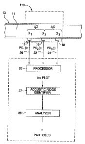
Figure 1 shows a system according to one embodiment of the invention for
detecting particles in a fluid 11 flowing within a conduit 13. An array of
pressure
sensors 14, 16, 18 provides signals 20, 22, 24 indicative of the fluid
pressure at each
sensor location at a number of successive instants of time. Additional sensors
or only
two sensors can also be used for some embodiments. The array of sensors 14,
16, 18
measures the unsteady pressure disturbances within the fluid 11 caused by sand
and
other phenomenon propagating with or within the fluid. The sensors 14, 16, 18
may
include fiber optic sensors that may coil around the conduit 13 in a series of
wraps. As
disclosed in the incorporated "flowmeter references," each wrap may be
separated by a
single Bragg grating for time division multiplexing (TDM) or each wrap may be
separated by a pair of Bragg gratings for wavelength division multiplexing
(WDM).
Other types of pressure sensors, such as electrical, piezofilm, polyvinylidene
fluoride
(PVDF), or mechanical sensors, can be used and are disclosed in the "flowmeter
references."
The sensors 14, 16, 18 produce time varying pressure (Px;(t)) signals
indicative
of the pressure of the acoustic disturbance detected at each of the sensors,
rendering
information about pressure as a function of both location (x) and time (t),
i.e., P(x,t).
For some embodiments, these pressure signals are converted at a processor 26
into a
5
CA 02573518 2011-08-26
kw plot, where k is wavenumber (27r/A), and w is the angular frequency (2,rf).
This
conversion is affected at the processor 26 and can involve the use of Fourier
Transform
algorithms. Other spatial/temporal conversions (e.g., a xw plot, a kt plot,
etc.) are also
possible such that the "kw plot" includes these other types of
spatial/temporal
conversions. A two-dimensional transform is utilized since two variables (x
and t) are
transformed into two different variables (w and k). Details of the foregoing
conversions,
physics of wave propagation inside a pipe containing a fluid, and other
relevant
considerations are disclosed in U.S. Patent No. 6,587,798.
Figure 2 illustrates an exemplary kw plot to be analyzed. The vertical axis of
the
plot is the temporal or angular frequency (w) of the signal in rad/s and the
horizontal
axis is the spatial frequency or wave number (k) (e.g., in 1/ft). Each point
(i.e.,
frequency) in the plot has associated with it a power level (in dB) denoted by
regions
100a-100d. The kw plot constitutes a data set in which each pixel comprises a
particular power value.
Accumulation of all of the acoustic events represented in the plot lie
generally
along straight lines, referred to as "ridges" 430. These ridges reflect the
fact that all of
the detected various acoustic events, each having its own unique frequency
constitutions, travel through the fluid at approximately the same speed
through the fluid,
i.e., the fluid speed of sound. This fluid speed of sound, c, can therefore be
calculated
by computing a best fit line(s) 410, 420 within the ridge(s), and determining
that line's
slope, where w = ck.
Power of the various acoustic phenomena that are represented in the kw plot
can be determined. Accordingly, regions 100a - 100d represent areas of
differing
power levels with region 100d representing the highest power levels (e.g., 20
db),
region 100c representing lower power levels (e.g., 10 db), etc. The power
regions are
more uneven or blotchy in shape than the idealized representation of the power
levels
depicted in the figures herein.
6
CA 02573518 2011-08-26
The kw plot allows for directionality of the acoustical disturbances to be
determined. Referring to Figure 1, the measured acoustics arrive at the sensor
array
110 as either left traveling waves or right traveling waves corresponding
respectively to
energy on the left side or the right side of the kw plot. Because the speed of
the fluid
flowing within the pipe is usually much smaller than the speed of sound in the
fluid,
these left traveling or right traveling acoustic disturbances approach the
array 110 at
approximately the same speed (assuming that the Mach number of the flow is
<<1).
Left traveling disturbances correspond to negative k values while right
traveling
disturbances correspond to positive k values. Thus, the kw plot exhibits two
ridges 430
since acoustics are generated from both the left and the right of the array
110. A first
ridge along line 410 is indicative of left traveling acoustics, and a second
ridge along
line 420 is indicative of right traveling acoustics. Because the left
traveling and right
traveling waves arrive at approximately the same speed, the absolute value of
the
slopes of both lines 410, 420 is approximately equal and indicative of the
speed of
sound in the fluid.
The ridges 430 in the kw plot are assessed in the system by a computerized
ridge identifier 27, as shown in Figure 1, which can identify the ridges 430
using
computerized techniques for assessing plots or plot data files. For example,
the ridge
identifier 27 can be preprogrammed with a power level threshold in which
pixels in the
plot having values exceeding this threshold are deemed to constitute a portion
of the
ridge 430. Once the area of the plot containing the ridge 430 has been
identified, its
slope (i.e., lines 410 and 420) can be determined by analyzer 28, which
preferably
employs a weighted least squares fitting algorithm or other fitting algorithm.
Referring still to Figure 1, the sensors 14, 16, 18 have suitable spacing
(preferably, equally spaced by OX) to detect acoustical frequencies selected
of interest.
If a single frequency component is considered, the disclosed system obtains
information about the wavelength A, (or the wave number k) of that frequency
component essentially by sensing the phase of that component at (at least) any
two of
the sensors 14, 16, 18. Thus, the separation OX can be determined to be a
particular
fraction of a wavelength of the sound to be measured. The information is only
7
CA 02573518 2011-08-26
unambiguous if the sensors sample frequently enough to avoid temporal aliasing
and
are close enough to avoid spatial aliasing. For example, the system may
incorrectly
indicate a value for the wavelength that is twice the actual value if the
sensors are a
distance AX apart that is two wavelengths of the frequency component being
measured. Additional sensors spaced at appropriate intervals can be added
should it
be necessary to resolve frequencies over a larger range than a single spacing
distance
permits.
The presence of sand attenuates power of the acoustics in the fluid.
Additionally
sand alters the speed of sound in the fluid such that decreasing speed of
sound
measurements correspond to increasing sand concentrations. Accordingly,
assessing
these effects on power and/or the speed of sound in the fluid can infer the
presence of
sand. Moreover, this detection using the sensor array 110 disclosed herein can
be
performed continuously and directly at the production pipe before sand reaches
the top
of the well.
Attenuation of acoustics detected with the sensor array 110 indicates presence
of sand with increasing attenuation corresponding to rising sand
concentrations.
Qualitative detection of sand can be made by detection of attenuation from a
base
signal where no sand is present. Additionally, quantitative detection of sand
can be
accomplished by calibrating the amount of attenuation with the concentration
of sand.
The attenuation due to sand occurs in frequency ranges above about 5 kHz.
Accordingly, the sensors and/or the processing equipment can collectively
analyze
frequency ranges of, for example, from 5 kHz to 20 kHz or from 5 kHz to 15
kHz.
With reference to the kw plot shown in Figure 2, the attenuation may be
visually
observed by diminished power indicated by diminution of regions 100a - '100d
to
respectively lower power levels. A further visual distinction may be present
based on a
change in a ratio of amplitude of the first ridge along line 410 to amplitude
of the second
ridge along line 420, as described further below regarding the Example.
Appropriate
algorithms of the analyzer 28 can automate the detection of sand based on this
observed attenuation within the kw plot.
8
CA 02573518 2011-08-26
Processing based on kw plots may apply temporal and spatial filtering
techniques to increase the effective signal-to-noise ratio, i.e., the
disclosed method may
only consider the attenuation of acoustics over a specific frequency range.
Other
signals of the sensor output such as electrical noise, vortical noise, impact
noise
propagating within the production tubing may all be effectively filtered out
by the
disclosed method.
Example:
Figure 3 illustrates an experimental setup that has been used to demonstrate
the
ability to detect sand flowing in a fluid as disclosed herein. The setup
provides a water
loop that includes a reservoir 300, a pump 302, a conduit 304 and a sensor
array 306
such as shown in Figure 1. In operation, the pump 302 urged water from the
reservoir
300 upward through the conduit 304 and sensor array 306 in the experiment
described
herein, prior to the water being returned to the reservoir 300. The pump was
operated
to provide a flow rate of 550.0 gallons per minute (gpm) corresponding to a
26.0 feet
per second flow velocity. Sand particles introduced into the water flow were
crystalline
silica with a mean diameter of 180.0 micron and a specific gravity of 2.65.
The volume
and mass percentages of the sand used in the experiments are shown in Table 1.
Table 1
Experiment Mass percentage of sand Volume of sand
0 0 0
1 1.5 0.57
2 3 1.14
Figure 4 illustrates an acoustic spectra plot for frequencies from 1.0 kHz to
10.0
kHz. Curve 600 represents a baseline recorded during Experiment 0 (no sand).
Comparatively, curve 602 identifies the signals generated during Experiment 1
(1.5%
mass sand) while curve 604 identifies the signal produced via Experiment 2 (3%
mass
sand).
9
CA 02573518 2011-08-26
Figure 5 shows an attenuation plot based on the detected signals shown in the
spectra plot in Figure 4. Line 702 represents the difference between spectral
levels of
Experiment 0 and Experiment 1. Similarly, line 704 represents the difference
between
spectral levels of the baseline with no sand and the higher 3% mass sand. The
addition of sand provided substantially no attenuation of acoustic signals
below 3.0
kHz, as evidenced by the difference being positive. However, sand introduced
into the
flow attenuated all signals from Experiments 1 and 2 in the spectra above 5.0
kHz.
Figure 6 illustrates a power ratio plot of Experiments 1 and 2 to Experiment
0, as
well as Experiment 2 to Experiment 1. The power ratio is lower for the higher
mass
loading of sand, as illustrated by line 800 corresponding to the power ratio
of
Experiment 2 to Experiment 1. For the line 800 and both line 802 corresponding
to the
power ratio of Experiment 1 to Experiment 0 and line 803 relating to the power
ratio of
Experiment 2 to Experiment 0, the power ratios are substantially constant and
all lower
than one above 5.0 kHz.
Figures 7-9 show schematically kw plots generated by the experiments without
sand, with 1.5% sand mass and with 3% sand mass, respectively. Contour
nomenclature as used in Figure 2 is maintained in these plots. These plots
evidence
that the acoustics diminished and acoustic signatures were altered with the
addition of
sand. For example, attenuation caused by the addition of sand changed a ratio
of
amplitude of the left side of the kw plots to amplitude of the right side of
the kw plots.
The left side of the kw plots indicate acoustic waves reaching the sensor
array 306
traveling from bottom to top while the right side of the kw plots indicate
acoustic waves
reaching the sensor array 306 traveling from top to bottom.
Higher amplitude of the power on the right side of the kw plot in Figure 7
indicates higher acoustic are generated above the sensor array 306. Weaker
amplitude
of the power on the left side of the plot resulted from acoustics originating
above the
sensor array returning after being reflected below the sensor array 306. These
reflected acoustics were weaker due to traveling a longer distance through the
fluid
even though no sand was present. Since sand in the water further attenuates
the
CA 02573518 2011-08-26
acoustics in terms of decibels per unit distance, addition of sand
disproportionately
diminished the acoustics from below the sensor corresponding to the left side
of the
plot. Consequently, the ratio of amplitude of the right side of the plot to
amplitude of the
left side of the plot is changed between each of Figures 7-9. For some
embodiments,
the acoustic being monitored may have an originating source below the sensor
array
306, which results in higher amplitude of the power on the left side of the kw
plot and
also inverts the ratio without otherwise altering the analysis.
Lines 900, 901 and 902 in Figures 7-9 identify a best fit of the data therein
such
that the slopes of the lines represent the speed of sound in the fluid. From
the slope of
the lines 900, 901 and 902, the speed of sound in Experiments 0 through 2 was
calculated at 2500 feet per second (ft/sec), 2450 ft/sec and 2350 ft/sec,
respectively.
The sound speed in water without entrained gas as measured with this
technology is
approximately 4650 ft/sec. Accordingly, Experiment 0 that did not have any
sand
provided a relatively lower sound speed due to entrained gas of about 200.0
part per
million (ppm).
'Theoretical acoustic models for particle suspensions, predict that sand
detection
is not possible in multiphase mixtures such as liquid and gas mixtures. These
theoretical models predict a strong sensitivity to gas but not solid
particles. While not
predicted by the conventional models, trends revealed by the experiments
described
herein indicated that sand can be detected even in the presence of gas. The
theoretical models describe a distorted acoustic signature due to sand
suspended in a
flowing mixture and attenuation and dispersion due to viscous dissipation, non-
viscous
inertial, and multiple scattering effects. The results of the experiments
showed
significant changes in attenuation that were not predicted.
Attenuation due to sand loading based on theoretical calculations using the
models is expected to be approximately 0.008 decibels (dB) and 0.016 dB for
the 1.5%
and 3% sand mass experiments, respectively. However, attenuation due to
increase in
gas volume fraction (GVF) based on theoretical calculations is expected to be
relatively
much higher than attenuation due to sand loading at frequency ranges above 5
kHz. In
11
CA 02573518 2011-08-26
other words, the attenuation due to increase in GVF is expected to be more
than two
orders of magnitude higher than the theoretical attenuation levels due to
sand.
Consequently, it was believed that even miniscule amounts of gas would cause
large
decreases in the speed of sound and dominate the attenuation effects.
The experiments further illustrate the results not being predicted by
hypothetically treating the observed change in speed of sound as only being
due to an
increase in gas bubbles in the water. Using this hypothetical assumption, the
GVF
values for Experiments 1 and 2 are 216.0 ppm and 244.0 ppm, respectively.
Relative
attenuation between the GVF of 200.0 ppm and these higher GVF values of 216.0
ppm
or 244.0 ppm is expected to be only on the order of less than about 1.0 or 2.0
dB,
respectively, for frequencies less than 10 kHz. Therefore, this relative
attenuation due
to any possible variation of GVF does not account for the attenuation levels
seen in
Figure 5, which is on the order of 20 dB.
For some embodiments, apparatus and methods as disclosed herein can detect
particulates in any pipe and in other industrial environments even though the
foregoing
describes detection of sand within a production pipe of an oil/gas well. The
scope of the
claims should not be limited by the preferred embodiments set forth in the
examples, but should be given
the broadest interpretation consistent with the description as a whole.
12