Language selection

Search

Patent 2573608 Summary

Third-party information liability

Some of the information on this Web page has been provided by external sources. The Government of Canada is not responsible for the accuracy, reliability or currency of the information supplied by external sources. Users wishing to rely upon this information should consult directly with the source of the information. Content provided by external sources is not subject to official languages, privacy and accessibility requirements.

Claims and Abstract availability

Any discrepancies in the text and image of the Claims and Abstract are due to differing posting times. Text of the Claims and Abstract are posted:

  • At the time the application is open to public inspection;
  • At the time of issue of the patent (grant).
(12) Patent Application: (11) CA 2573608
(54) English Title: METHOD FOR MEASURING THE SAGGING OF A GLASS PANEL
(54) French Title: PROCEDE PERMETTANT DE MESURER L'AFFAISSEMENT D'UNE PLAQUE DE VERRE
Status: Deemed Abandoned and Beyond the Period of Reinstatement - Pending Response to Notice of Disregarded Communication
Bibliographic Data
(51) International Patent Classification (IPC):
  • G1B 11/24 (2006.01)
  • C3B 23/025 (2006.01)
(72) Inventors :
  • JANHUNEN, TOIVO (Finland)
(73) Owners :
  • TAMGLASS LTD. OY
(71) Applicants :
  • TAMGLASS LTD. OY (Finland)
(74) Agent: BERESKIN & PARR LLP/S.E.N.C.R.L.,S.R.L.
(74) Associate agent:
(45) Issued:
(86) PCT Filing Date: 2005-06-30
(87) Open to Public Inspection: 2006-01-19
Availability of licence: N/A
Dedicated to the Public: N/A
(25) Language of filing: English

Patent Cooperation Treaty (PCT): Yes
(86) PCT Filing Number: PCT/FI2005/050261
(87) International Publication Number: FI2005050261
(85) National Entry: 2007-01-11

(30) Application Priority Data:
Application No. Country/Territory Date
20045273 (Finland) 2004-07-14

Abstracts

English Abstract


The present invention relates to a method for measuring the sagging of a glass
panel (6) in the process of bending the glass panel (6) on a ring mould (4).
The method comprises measuring the sagging at a glass panel's measuring point
and the measurement data is applied to control progress of the bending
process, especially heating of the glass panel (6) or abortion of the bending
process. A reference plane (5a, 5b) stationary with respect to the ring mould
(4) is established, a distance gauge (7, 70) is used for measuring a distance
between the reference plane (5a, 5b) and the distance gauge (7, 70), a
distance gauge (7, 70) is used for measuring a distance between the glass
panel's (6) measuring point and the distance gauge (7, 70). The glass panel's
(6) sagging is determined by comparing the distance between the reference
plane (5a, 5b) and the distance gauge (7, 70) to the distance between the
glass panel's (6) measuring point and the distance gauge (7, 70).


French Abstract

L'invention concerne un procédé permettant de mesurer l'affaissement d'une plaque de verre (6) dans le processus de cintrage de la plaque de verre (6) sur un moule en couronne (4). Le procédé consiste à mesurer l'affaissement au niveau d'un point de mesurage d'une plaque de verre et à utiliser les données de mesurage afin de réguler l'avancement du processus de cintrage, notamment le chauffage de la plaque de verre (6) ou l'interruption du processus de cintrage. Un plan de référence (5a, 5b) fixe par rapport au moule en couronne (4) est établi, un indicateur de distance (7, 70) est utilisé pour mesurer une distance entre le plan de référence (5a, 5b) et l'indicateur de distance (7, 70), un indicateur de distance (7, 70) est utilisé pour mesurer une distance entre le point de mesurage de la plaque de verre (6) et l'indicateur de distance (7, 70). Pour déterminer l'affaissement de la plaque de verre (6), on compare la distance entre le plan de référence (5a, 5b) et l'indicateur de distance (7, 70) à la distance entre le point de mesurage de la plaque de verre (6) et l'indicateur de distance (7, 70).

Claims

Note: Claims are shown in the official language in which they were submitted.

7
Claims
1. A method for measuring the sagging of a glass panel (6) in the process of
bending the glass panel (6) on a ring mould (4), said method comprising
establishing a reference plane (5a, 5b) stationary or positionally fixed with
respect to the ring mould (4) and measuring the sagging at a glass panel's
measuring point and the measurement data being applied to control
progress of the bending process, especially heating of the glass panel (6) or
abortion of the bending process, characterized in that a distance gauge (7,
70), including a transmitter and a receiver for laser pulses, is used for
measuring a distance between the reference plane (5a, 5b) and the distance
gauge (7, 70) by determining the transmission time of a laser pulse (7a)
from transmitter to receiver, a distance gauge (7, 70) is used for measuring
a distance between the glass panels (6) measuring point and the distance
gauge (7, 70) by determing the transmission time of the laser pulse (7a)
from transmitter to receiver, and the glass panel's (6) sagging is determined
by comparing the distance between the reference plane (5a, 5b) and the
distance gauge (7, 70) to the distance between the glass panel's (6)
measuring point and the distance gauge (7, 70).
2. A method as set forth in claim 1, characterized in that the first distance
gauge (7) is used for measuring the sagging of a pre-bent glass panel (6)
prior to a final bending process and the second distance gauge (70) is used
for measuring the sagging of the glass panel (6) during a final bending
process.
3. A method as set forth in claim 1 or 2, characterized in that the glass
panel's (6) sagging is measured at several measuring points successive in the
glass panel's (6) advancing direction.
4. A method as set forth in any of the preceding claims 1-3, characterized
in that the glass panel (6) lies between two reference planes (5a, 5b) in the
glass panel's (6) advancing direction.

8
5. A method as set forth in any of the preceding claims 1-4, characterized
in that the reference plane (5a, 5b) and/or the measuring point are located
essentially on the ring mould's centre axis of symmetry.

Description

Note: Descriptions are shown in the official language in which they were submitted.


CA 02573608 2007-01-11
WO 2006/005805 PCT/F12005/050261
1
Method for measuring the sagging of a glass panel
The present invention relates to a method for measuring the sagging of a
glass panel in the process of bending the glass panel on a ring mould, said
method comprising establishing a reference plane stationary or positionally
fixed with respect to the ring mould and measuring the sagging at a glass
panel's measuring point and the measurement data being applied to control
progress of the bending process, especially heating of the glass panel or
abortion of the bending process.
This type of method for measuring a glass panel's sagging is prior known
from Finnish patent application FI-912871. That comprises monitoring the
sagging with a measuring instrument for applying a laser beam to the
surface of a glass panel and a CCD camera is used for tracking the distance
of a confluence point between glass and laser beam from a reference plane.
This arrangement requires a lot of space and sets constraints regarding the
choice of a measuring point. An angle of reflection required for the laser
beam calls for two holes in the roof of an oven for each measuring point and
accuracy is not sufficient because of the angle of reflection.
Patent application WO 02/23124 discloses a method, in which a line camera
is used for tracking the angle of reflection of a light beam reflected from
glass. The angle of reflection is highly sensitive to a possible surface
defect in
glass and to a local curvature defect in glass, whereby the angle of
reflection
provides a defective measuring result. This method may also involve
measuring the distance of a reflection point from the camera by applying a
second light source and the triangulation principle.
In addition to the above, there are a host of prior known methods, disclosed
for example in publications FI 850120 and FI 98757, wherein light beams
reflected from an arched or arching glass panel are monitored in various
ways by means of a line or matrix camera or cameras. These methods are

CA 02573608 2007-01-11
WO 2006/005805 PCT/F12005/050261
2
hampered by problems similar to those found in the method disclosed in
publication WO 02/23124.
It is an object of the present invention to eliminate or substantially
alleviate
the above drawbacks.
In order to achieve the above object, a method of the present invention is
characterized in that a distance gauge, including a transmitter and a receiver
for laser pulses, is used for measuring a distance between the reference
plane and the distance gauge by determining the transmission time of a laser
pulse from transmitter to receiver, a distance gauge is used for measuring a
distance between the glass panels measuring point and the distance gauge
by determing the transmission time of the laser pulse from transmitter to
receiver, and the glass panel's sagging is determined by comparing the
distance between the reference plane and the distance gauge to the distance
between the glass panel's measuring point and the distance gauge.
Preferred embodiments of the present invention are set forth in the
dependent claims.
The invention will now be described in more detail with reference to the
accompanying drawings, in which:
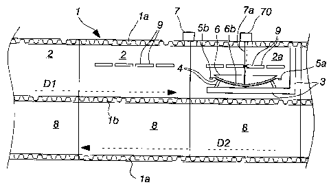
Fig. 1 shows schematically an apparatus of the invention in a side view,
and
Fig. 2 shows schematically an apparatus of the invention in a plan
view.
Thus, figs. 1 and 2 depict one embodiment for an apparatus applying a
method of the invention. There is shown a section of an oven 1 designed for
bending a glass panel 6. The oven 1 includes an elongated space defined by
walls la, which is divided by means of a floor lb or the like for two

CA 02573608 2007-01-11
WO 2006/005805 PCT/F12005/050261
3
elongated spaces on top of each other. The upper of these spaces is divided
by the vertical walls of mould carriages 3 for successive preheating
compartments 2, followed by an actual bending compartment 2a for the
glass panel 6, in which the inventive method for measuring the glass panel's
6 sagging is actually applied. The glass panel is generally heated by means of
resistances 9 disposed in the heating compartments 2 and in the actual
bending compartment 2a. The section of an oven downstream of the
bending compartment includes usually a lift compartment (not shown),
whereby the bent glass panel 6 is conveyed into the lower space. The lower
space is divided by the vertical walls of mould carriages 3 for successive
cooling compartments 8 for performing a controlled cooling of the glass
panel.
The glass panel 6 is carried on the mould carriage 3 along a conveying track
provided in the oven 1 in a per se known manner from one compartment to
the next. The glass panel 6 is laid on a ring mould 4 attached to the mould
carriage 3. The advancing direction of an upper conveying track is indicated
by reference numeral Dl and the traveling direction of a lower conveying
track is indicated by reference numeral D2. The method comprises
preheating the glass 6 on top of the ring mould 4 in the compartments 2. In
the process of bending on the ring mould 4, the glass 6 is not supported at
all in its middle section, but only along its periphery. As the mould carriage
3,
and thereby also the glass panel 6, proceeds from the preheating
compartment 2 to the bending compartment, the glass panel 6 may already
be in a somewhat bent condition in its middle section. The actual bending,
i.e. providing the glass panel 6 with a desired sagging, is performed in the
bending compartment 2a.
In view of measuring the above sagging, between the preheating
compartment 2 and the bending compartment 2a, outside the compartments
2 and 2a, preferably on top of the oven 1, is disposed a first distance gauge
or sensor 7, which defines a first measuring point for the glass panel 6 in
the
proceeding direction of the track Dl. In addition to this, on top of the

CA 02573608 2007-01-11
WO 2006/005805 PCT/F12005/050261
4
bending compartment 2a, preferably above the glass panel's 6 middle section
(with the glass panel immobilised in the bending compartment 2a), is
disposed a second distance gauge or sensor 70, which is preferably identical
in its design and function to the distance gauge 7 placed between the
compartments. The second distance gauge 70 defines a second measuring
point. This gauge 7 and 70, used for applying the method, comprises a
transmitter and a receiver. The transmitter applies to the glass panel's 6
middle section, the surface thereof, at desired intervals, a short laser pulse
7a which reflects from the glass panel's 6 surface to the receiver. The
distance can be determined on the basis of the laser pulse's 7a proceeding
time from transmitter to receiver. The gauges 7 and 70 measure this
proceeding time. The measurement can be performed at each measuring
point from a single hole in the oven's roof, the space demand being modest
and the measuring point or a plurality of measuring points being easy to
choose.
In order to obtain this measuring result, it is necessary to establish a
reference plane in conjunction with the glass panel 6 for comparing
therewith the result measured from the middle of the glass panel 6.
Therefor, the ring mould 4 or the mould carriage 3, preferably along the ring
mould's 4 centre axis of symmetry, is provided with markers 5a and 5b or
identification tags. Viewed in the proceeding direction Dl, the markers are
positioned in the carriage's leading and trailing sections in such a way that
the glass panel 6 is held therebetween in its advancing direction.
A first measurement is performed while conveying the carriage 3 from the
preheating compartment 2 to the bending compartment 2a. The first
measurement involves using the distance gauge 7 for measuring a distance
between the reference plane 5a and the distance gauge 7. Thus, it is
preferred that the marker 5a be provided with a reflective surface for a laser
pulse to reflect back to the distance gauge 7. A first fixed reference plane
is
thereby established for a second measurement. Next, the second
measurement involves using the distance gauge 7 for measuring a distance

CA 02573608 2007-01-11
WO 2006/005805 PCT/F12005/050261
between the glass panel's 6 measuring point and the distance gauge 7. The
glass panel's 6 sagging is determined by comparing at least these two
measuring results to each other. The glass panel 6 may have its surface 6b
provided in the glass panel's 6 advancing direction even with a plurality of
5 successive measuring points or the measurement may proceed almost
continuously for providing a sagging profile in almost solid line.
As the mould carriage 3 proceeds further along its track Dl, the trailing
marker 5b will also pass by the discussed measuring point for providing a
second reference plane. Thus, the mould-specific reference data can be
readily obtained from two locations (a measurement of two reference planes
enables a more precise determination of the reference plane than a
measurement of just one reference plane), and also obtained is information
about possible sagging caused by preheating. This information can be
utilized, for example, in the process of determining or regulating beforehand
an on/off pattern or effects produced by the bending compartment's 2a
resistances 9 in preparation of bending the discussed glass panel 6. The
measurement data can also be used in the process of regulating the
preheating compartments' 2 heating effect for subsequent glass panels.
The actual sagging measurement, in other words a measurement for a
distance and variation of distance to the immobilised glass panel's 6 centre
(measuring point), is performed with the second distance gauge 70 during
the bending process as shown in fig. 1. In order to ensure a correct
measuring result, the second gauge 70 also needs a reference plane, which it
acquires by measuring a distance to the marker 5a carried along with the
mould 4 proceeding into the bending compartment 2a. The measuring result
obtained from the measuring point is compared to the reference plane
measured by the second gauge 70. In addition to or instead of this, it is
possible to effect a comparison with the reference planes measured by the
first gauge 7. With regard to the marker 5b, the only available measuring
result is the one provided by the first gauge 7. It is further possible to
perform a measurement of sagging and a process control during the bending

CA 02573608 2007-01-11
WO 2006/005805 PCT/F12005/050261
6
process without the first measurement effected by the first gauge 7. By
tracking the measuring result or results, the heating process (resistances)
can be controlled for producing a desired sagging. Once a desired sagging is
achieved, the bending process can be stopped and the glass panel 6 carried
along on its track Dl for further processing.
The number of gauges 7, 70 can be one, two or more. A practical
implementation of the invention requires at least a gauge 70 present in the
bending compartment. The number of reference planes 5a, 5b can also be
one, two or more for each bending mould. Each reference plane 5a, 5b must
be immobile or positionally fixed relative to the mould 4.

Representative Drawing
A single figure which represents the drawing illustrating the invention.
Administrative Status

2024-08-01:As part of the Next Generation Patents (NGP) transition, the Canadian Patents Database (CPD) now contains a more detailed Event History, which replicates the Event Log of our new back-office solution.

Please note that "Inactive:" events refers to events no longer in use in our new back-office solution.

For a clearer understanding of the status of the application/patent presented on this page, the site Disclaimer , as well as the definitions for Patent , Event History , Maintenance Fee  and Payment History  should be consulted.

Event History

Description Date
Time Limit for Reversal Expired 2010-06-30
Application Not Reinstated by Deadline 2010-06-30
Deemed Abandoned - Failure to Respond to Maintenance Fee Notice 2009-06-30
Inactive: Cover page published 2007-03-15
Letter Sent 2007-03-07
Inactive: Notice - National entry - No RFE 2007-03-07
Application Received - PCT 2007-02-08
National Entry Requirements Determined Compliant 2007-01-11
Application Published (Open to Public Inspection) 2006-01-19

Abandonment History

Abandonment Date Reason Reinstatement Date
2009-06-30

Maintenance Fee

The last payment was received on 2008-06-03

Note : If the full payment has not been received on or before the date indicated, a further fee may be required which may be one of the following

  • the reinstatement fee;
  • the late payment fee; or
  • additional fee to reverse deemed expiry.

Patent fees are adjusted on the 1st of January every year. The amounts above are the current amounts if received by December 31 of the current year.
Please refer to the CIPO Patent Fees web page to see all current fee amounts.

Fee History

Fee Type Anniversary Year Due Date Paid Date
MF (application, 2nd anniv.) - standard 02 2007-07-03 2007-01-11
Basic national fee - standard 2007-01-11
Registration of a document 2007-01-11
MF (application, 3rd anniv.) - standard 03 2008-06-30 2008-06-03
Owners on Record

Note: Records showing the ownership history in alphabetical order.

Current Owners on Record
TAMGLASS LTD. OY
Past Owners on Record
TOIVO JANHUNEN
Past Owners that do not appear in the "Owners on Record" listing will appear in other documentation within the application.
Documents

To view selected files, please enter reCAPTCHA code :


To view images, click a link in the Document Description column (Temporarily unavailable). To download the documents, select one or more checkboxes in the first column and then click the "Download Selected in PDF format (Zip Archive)" or the "Download Selected as Single PDF" button.

List of published and non-published patent-specific documents on the CPD .

If you have any difficulty accessing content, you can call the Client Service Centre at 1-866-997-1936 or send them an e-mail at CIPO Client Service Centre.


Document
Description 
Date
(yyyy-mm-dd) 
Number of pages   Size of Image (KB) 
Drawings 2007-01-10 2 33
Abstract 2007-01-10 1 68
Claims 2007-01-10 2 51
Description 2007-01-10 6 253
Representative drawing 2007-03-13 1 13
Cover Page 2007-03-14 1 51
Notice of National Entry 2007-03-06 1 192
Courtesy - Certificate of registration (related document(s)) 2007-03-06 1 105
Courtesy - Abandonment Letter (Maintenance Fee) 2009-08-24 1 174
Reminder - Request for Examination 2010-03-01 1 119
PCT 2007-01-10 3 125