Note: Descriptions are shown in the official language in which they were submitted.
CA 02573812 2007-01-12 05PCT041 MY
[Designation of Document] Description
[Title of the Invention]
ACTIVE IRON POWDER, HEAT GENERATING COMPOSITION, AND
HEAT GENERATING BODY
[Technical Field]
[0001]
The present invention relates to an active iron powder
which is used in a heat generating body and to a heat generating
composition and a heat generating body.
[Background Art]
[0002]
As products to be used by making air (oxygen) act on a
mixture of an iron powder and a reaction aid, etc. , in general,
throwaway body warmers and so-called oxygen-free scavengers
which are installed in a packaging body of various foods and
efficiently absorb oxygen in the packaging body, thereby
preserving the freshness of foods are well known.
[0003]
As metal powders to be used in these products, an iron
powder is the most general, and as the reaction aid, salt,
water, and the like are used. It is also well known that as
a water retaining agent for carrying such a substance thereon,
active carbon, vermiculite, diatomaceous earth, a wood meal,
a water absorptive polymer, and the like are mixed and used.
[0004]
1
CA 02573812 2007-01-12
A role of the iron powder in a throwaway body warmer is
to utilize reaction heat as generated due to oxidation,
thereby achieving the purpose. Accordingly, the performance
of such a product is influenced by characteristics of the iron
powder. In other words, if an iron powder having high activity
is used, favorable products are produced.
In a throwaway body warmer, since what the temperature
rises immediately after breaking the seal enhances a product
value, it is desired to supply an iron powder having excellent
exothermic rising characteristics (see, for example, Patent
Documents 1 and 2).
Usually, in commercially available iron powders, the
degree of reduction is strong, and the purity of iron is high.
When used for a heat generating body, exothermic rising
properties are insufficient, and it is attempted to improve
the exothermic rising properties chiefly by adjusting the
amount of addition of a carbon component such as active carbon.
However, satisfactory results have not been obtained yet in
view of the performance. Furthermore, in a reduced iron powder
which is usually used in a chemical body warmer, there is some
possibility that the presence of an iron oxide film is formed
by air oxidation during the storage or the like. However, the
iron oxide film in such a form does not contribute to the
exothermic rising properties of a heat generating
composition.
2
CA 02573812 2007-01-12
On the other hand, by forming a fixed amount of a thin
film of a conductive carbonaceous substance locally on the
surface of an iron powder, an active iron powder whose surface
has been modified such that an oxidation reaction is promoted
is known as a raw material for throwaway body warmers or
oxygen-free scavengers.
However, according to the method for forming a fixed
amount of a thin film of a conductive carbonaceous substance
locally on the surface of iron, though the exothermic rising
properties of a heat generating composition are improved, its
effect is insufficient and a production step becomes
complicated. Thus, there was involved a problem in view of
costs.
[0005]
[Patent Document 1] JP-A-53-60885
[Patent Document 2] JP-A-57-10673
[Disclosure of the Invention]
[Problems that the Invention is to Solve]
[0006]
An object of the invention is to provide an active iron
powder which is suitable for a heat generating composition of
a heat generating body, is excellent in rising properties and
is excellent in economy by using an iron powder which is
generally produced at present and modifying its function into
an active iron powder suitable as a raw material of a heat
3
CA 02573812 2007-01-12
generating body.
[Means for Solving the Problems]
[0007]
The present inventors made extensive and intensive
investigations and examined a production process of an iron
powder and examined exothermic rising properties of a heat
generating composition by treating a reduced iron powder with
an oxidizing gas and using various iron powders as prepared
by changing their conditions and compounding, and the like.
As a result, it has been noted that in an iron powder having
favorable exothermic rising properties of a heat generating
composition, at least a part of the surface of an iron powder
is covered by an iron oxide film. In addition, as a result
of examining the thickness of the foregoing iron oxide film
by the Auger electron spectroscopy, it has been found that
there is a relation in which when the thickness of the iron
oxide film is thick, the exothermic rising properties become
favorable.
As set forth in claim 1, active iron powder to be
contained in a heat generating composition capable of
generating heat upon contact with air, characterized in that
in the active iron powder comprising particles, a surface of
each of which is at least partially covered with an iron oxide
film; and that a thickness of the iron oxide film is from 3
nm to 100 m and is not more than 50 % of the total thickness
4
CA 02573812 2007-01-12
of the particles.
Also, an active iron powder as set forth in claim 2 is
characterized in that in the active iron powder as set forth
in claim 1, the active iron powder is at least one member
selected from a reduced iron power, an atomized iron powder,
and an iron powder partially covered by a conductive
carbonaceous substance.
As set forth in claim 3, a heat generating composition
of the invention is a heat generating composition containing,
as essential components, an iron powder, a carbon component,
a reaction accelerator and water, which is characterized in
that the active iron powder as set forth in claim 1 accounts
for from 30 to 100 % by weight of the iron powder in the heat
generating composition.
As set forth in claim 4, a heat generating body of the
invention is characterized by containing the heat generating
composition as set forth in claim 3.
Also, the heat generating body as set forth in claim 5
is characterized in that in the heat generating body as set
forth in claim 4, the heat generating body has fixing means
in at least a part thereof.
Also, the heat generating body as set forth in claim 6
is characterized in that in the heat generating body as set
forth in claim 5, the fixing means is an adhesive layer and
contains at least one member selected from additional
CA 02573812 2007-01-12
components consisting of a water retaining agent, a water
absorptive polymer, a pH adjusting agent, a surfactant, an
organosilicon compound, a hydrophobic polymer compound, a
pyroelectric substance, an antioxidant, an aggregate, a
fibrous material, a moisturizer, a functional substance, and
a mixture thereof.
[Advantages of the Invention]
[0008]
As is clear from the foregoing description, by forming
an iron oxide film having a thickness, as measured by the Auger
electron spectroscopy, of from 3 nm to 100 m at least on the
surface of an iron powder as produced by reduction of iron
oxide or at least on the surface of a commercially available
iron powder or an iron powder as produced as an intermediate
stage product of processing and production, an active iron
powder for heat generating body which is not only suitable as
a raw material of heat generating body and excellent in
exothermic rising properties but also excellent in economy is
obtainable.
By using the active iron powder of the invention as an
iron powder for heat generating body, not only exothermic
characteristics, especially initial rising characteristics
can be improved, but also the amounts of a combustion improver
and active carbon in the active components can be reduced.
Concretely, it is possible to reduce the amount of a carbon
6
CA 02573812 2007-01-12
component such as active carbon in the heat generating
composition by 10 to 20 % or more. By reducing the amount of
addition of the carbon component, it is possible to reduce
costs.
[Best Modes for Carrying Out the Invention]
[0009]
Although a mechanism in which when the active iron
powder of the invention is used as an iron powder for heat
generating body, exothermic rising properties of the heat
generating composition are improved has not be elucidated in
detail, it is assumed that when components are brought into
contact with an oxidizing gas to cause oxidation of the
components, in particular, oxidation of an iron powder, not
only an iron oxide film, i.e., an oxygen-containing film, is
formed on the surface of the iron powder particles, but also
the oxidized iron component is also adhered on the surface of
active carbon, whereby hydrophilicity is imparted or improved
on the both to cause coupling or structurization among the
components through the mediation of water. Furthermore, it
is assumed that when an iron oxide film is formed on the surface
of the iron powder particles, some functional change occurs,
whereby exothermic rising properties are improved. Moreover,
the case where magnetite (Fe304) is present in the iron oxide
film is preferable because it is excellent in conductivity.
The case where hematite (Fe203) is present in the iron oxide
7
CA 02573812 2007-01-12
film is also preferable because it becomes porous.
[0010]
The iron powder of the invention constitutes a heat
generating composition capable of generating heat upon
contact with air, in which at least a part of the surface of
the iron powder is covered by an iron oxide film, and a
thickness of the iron oxide film is from 3 nm to 100 m and
is not more than 50 % of the total thickness of the iron powder.
When the thickness of the iron oxide film is thick, a
gas is formed to cause a problem that an outer bag is swollen
during a period of time when the heat generating body is stored
in an air-impermeable accommodating bag. For that reason, it
is preferred to use a small amount of a hydrogen gas formation
inhibitor.
The hydrogen formation inhibitor is not limited so far
as it inhibits the formation of hydrogen. Examples thereof
include at least one or two or more members selected from the
group consisting of sulfur compounds, oxidizing agents,
alkaline substances, sulfur, antimony, selenium, phosphorus,
and tellurium.
The sulfur compound is a compound with an alkali metal
or alkaline earth metal, and examples thereof include metal
sulfides such as calcium sulfide, metal sulfites such as
sodium sulfite, and metal thiosulfates such as sodium
thiosulfate.
8
CA 02573812 2007-01-12
Examples of the oxidizing agent include nitrates,
oxides, peroxides, halogenated hydroacid salts,
permanganates, and chromates.
The alkaline substance is not limited so far as it is
a substance exhibiting alkaline properties. Examples thereof
include silicates, phosphates, sulfites, thiosulfates,
carbonates, hydrogencarbonates, hydroxides, Na3PO4r and
Ca (OH) 2.
[0011]
Examples of the iron powder include a cast iron powder,
an atomized iron powder, an electrolyzed iron powder, a
reduced iron power, an iron powder whose surface is partially
covered by a conductive carbonaceous substance, and iron
alloys thereof.
In particular, an iron powder or an iron alloy powder
wherein the iron component is an iron powder or an iron alloy
powder, the surface of which is partially covered by from 0.3
to 3.0 % by weight of a conductive carbonaceous substance, is
useful.
Incidentally, the iron powder or active iron powder may
contain a metal other than iron, a semiconductor, or an oxide
thereof.
Furthermore, the iron powder may be an iron powder which
contains a carbon component and/or is partially covered by a
carbon component.
9
CA 02573812 2007-01-12
The "iron alloy powder" as referred to herein is an iron
alloy powder containing 50 % or more of iron. The alloy
component is not particularly limited so far as it is a metal
component including semiconductors other than iron and the
iron component functions as a component of the heat generating
composition, and examples thereof include silicon, zinc,
aluminum, magnesium, manganese, nickel, and copper.
As the metal oxide other than iron oxide in the iron
component which contains oxygen and/or is covered by oxygen,
any substance may be employed so far as it does not hinder the
oxidation of iron by an oxidizing gas. Examples thereof
include manganese dioxide and cupric oxide.
[0012J
The "thickness of the iron oxide film" as referred to
herein means a portion in which in the case of sputtering the
surface of the iron powder with Ar at a sputtering rate of 11
nm/min as reduced into Fe in the depth direction by using the
Auger electron spectroscopy, a ratio (Io/Ii) of a peak
intensity of 0(Io) to a peak intensity of Fe (Ii) is 0.05 or
more. Accordingly, the thickness of the oxygen-containing
film of iron according to the invention is a distance, as
reduced into Fe, from the surface of the iron powder to a depth
at which (Io/Ii) is 0.05. With respect to the measurement
condition of the Auger electron spectroscopy, the sputtering
time is 15 minutes, and the sputtering rate is 11 nm/min (as
CA 02573812 2007-01-12
reduced into Fe). With a lapse of the sputtering time, Io
decreases, whereas Ii increases. By reducing the sputtering
time from the surface of the iron powder to a depth at which
(Io/Ii) is 0.05 into a thickness, the thickness of the iron
oxide film can be calculated.
The thickness of the iron oxide film which covers the
surface of the iron powder is usually from 3 nm or more,
preferably from 3 nm to 100 m, more preferably from 30 nm to
100 m, further preferably from 30 nm to 50 m, still further
preferably from 30 nm to 1 m, even further preferably from
30 nm to 500 nm, and even still further preferably from 50 nm
to 300 nm by using the Auger electron spectroscopy. When the
thickness of the oxygen-containing film of iron is 3 nm or more,
the thickness of the oxygen-containing film of iron is able
to exhibit an effect for promoting an oxygen reaction, and upon
contact with an oxidizing gas such as air, the oxidation
reaction can be immediately initiated.
When the thickness of the oxygen- containingfilm of iron
is 3 nm or more, an oxygen reaction is promoted by the
oxygen-containing film of iron, and upon contact with an
oxidizing gas such as air, the oxidation reaction can be
immediately initiated.
When the thickness of the oxygen- containingfilm of iron
exceeds 100 m, though there is some possibility that the
exothermic time is shortened, such can be employed depending
11
CA 02573812 2007-01-12
upon the utility.
Furthermore, examples of the iron oxide which con-
stitutes the iron oxide film of the invention include irons
containing oxygen such as oxides, hydroxides and oxy-
hydroxides of iron.
[0013]
The production process of an active iron powder
according to the invention is not limited so far as at least
a part of the surface of the iron powder is covered by an iron
oxide film and the thickness of the iron oxide film can be
regulated at from 3 nm to 100 m. Examples thereof include
a contact treatment with an oxidizing gas in which a reaction
mixture having components of a heat generating composition
mixed therein or a heat generating composition is brought into
continuous or intermittent contact with an oxidizing gas (for
example, oxygen and air) in an oxidizing gas atmosphere or by
blowing an oxidizing gas, or the like, thereby partially
oxidizing the iron component. A method for determining a
degree of oxidation is not limited. Examples thereof include
a method of determining a degree of contact of the reaction
mixture or heat generating composition with an oxidizing gas
by a water mobility value of the reaction mixture or heat
generating composition, a contact time with an oxidizing gas,
an exothermic temperature rise rate at the time of contact,
an exothermic temperature at the time of contact, a maximum
12
CA 02573812 2007-01-12
exothermic temperature at the time of contact, a prescribed
temperature as dropped after reaching a maximum exothermic
temperature at the time of contact, or a combination thereof,
thereby determining a degree of oxidation.
In addition, the following can be specifically
enumerated.
(1) A production process by reducing a mill scale or an
ore to be used as a raw material of an iron powder at a
temperature of not higher than about 1,300 C by using a
reducing agent such as hydrogen, charcoal, and coke, coarsely
pulverizing the reduced cake by a hammer mill, a jaw crusher,
etc., and then finely pulverizing it by a novorotor, a
pulverizer, or a vibration bowl.
(2) A production process by reducing an iron powder
containing an iron oxide, thereby producing a partially
oxidized iron powder.
(3) A production process by exposing and allowing an
iron powder to stand in air, thereby producing a partially
oxidized iron powder.
(4) A production process by exposing and allowing a
mixture of an iron powder, a reaction accelerator and water
to stand in air, thereby producing a partially oxidized iron
powder.
(5) A production process by subjecting a reaction
mixture of an iron powder, a reaction accelerator and water
13
CA 02573812 2007-01-12
in an oxidizing gas atmosphere to a self-exothermic reaction
to partially oxidize the iron powder, thereby producing a
partially oxidized iron powder.
(6) A production process by subjecting a reaction
mixture of an iron powder, a reaction accelerator, an acidic
substance and water in an oxidizing gas atmosphere to a
self-exothermic reaction to partially oxidize the iron powder,
thereby producing a partially oxidized iron powder.
(7) A production process by subjecting a reaction
mixture of an iron powder, a reaction accelerator, a carbon
component and water in an oxidizing gas atmosphere to a
self-exothermic reaction to partially oxidize the iron powder,
thereby producing a partially oxidized iron powder.
(8) A production process by subjecting a reaction
mixture of an iron powder, a reaction accelerator, an acidic
substance, a carbon component and water in an oxidizing gas
atmosphere to a self-exothermic reaction to partially oxidize
the iron powder, thereby producing a partially oxidized iron
powder.
(9) A production process by bringing a reaction mixture
containing, as essential components, an iron powder, a
reaction accelerator, a carbon component and water and having
a water content of from 1 to 30 % by weight and a water mobility
value of less than 0.01 into contact with an oxidizing gas and
holding the temperature of the reaction mixture at the time
14
CA 02573812 2007-01-12
of contact at 40 C or higher for 2 seconds or more, thereby
producing an active iron powder.
(10) A production process by containing other component
than the essential components in the reaction mixture as set
forth above in any one of (7) to (9), thereby producing a
partially oxidized iron powder.
Incidentally, the term "other component than the
essential components" as referred to herein means at least one
member selected from additional components consisting of a
water retaining agent, a water absorptive polymer, a pH
adjusting agent, a hydrogen formation inhibitor, an aggregate,
a fibrous material, a functional substance, a surfactant, an
organosilicon compound, a pyroelectric substance, a
moisturizer, a fertilizer component, a hydrophobic polymer
compound, a heat generating aid, a metal other than iron, a
metal oxide other than iron oxide, an acidic substance, and
a mixture thereof. If desired, a magnetic body may be further
added.
(11) A production process by carrying out a process as
set forth above in any one of (1) to (5) by using a reaction
mixture having a water mobility value of less than 0.01,
thereby producing a partially oxidized iron powder.
(12) A production process by carrying out a process as
set forth above in any one of (1) to (6) by using a reaction
mixture having a water mobility value of less than 0.01 and
CA 02573812 2007-01-12
a water content of from 0.01 to 20 % by weight, thereby
producing a partially oxidized iron powder.
(13) A production process by carrying out a process as
set forth above in any one of (1) to (5) by using a reaction
mixture having a water mobility value of 0.01 or more, thereby
producing a partially oxidized iron powder.
(14) A production process by carrying out a process as
set forth above in any one of (1) to (8) by warming at 10 C
or higher, thereby producing a partially oxidized iron powder.
(15) A production process by carrying out a process as
set forth above in any one of (1) to (8) by blowing an oxidizing
gas, thereby producing a partially oxidized iron powder.
(16) A production process by carrying out a process as
set forth above in (11) by blowing an oxidizing gas warmed at
C or higher, thereby producing a partially oxidized iron
powder.
(17) A production process by carrying out a process as
set forth above in any one of (1) to (12), wherein the water
content in the mixture prior to the contact treatment with an
oxidizing gas is from 0.5 to 30 %, and the contact treatment
with an oxidizing gas is carried out until the temperature
reaches a maximum temperature which is a maximum point of a
temperature rise due to the exothermic reaction or exceeds the
maximum temperature, thereby producing a partially oxidized
iron powder (in this case, it is preferable that the contact
16
CA 02573812 2007-01-12
treatment with an oxidizing gas is carried out until the
temperature drops by at least 10 to 20 C from the maximum
temperature).
Incidentally, the circumstances of the reaction mixture
part at the time of the contact treatment with an oxidizing
gas are not limited. Examples thereof include a state that
it is present in a vessel and a state that the reaction mixture
is present in an air-permeable sheet-like material such as
non-woven fabrics. Furthermore, the contact treatment with
an oxidizing gas may be carried out with stirring or without
stirring and may be carried out in a batchwise system or
continuous system.
[0014]
Here, with respect to the state of the reaction mixture
at the time of the contact treatment with an oxidizing gas,
so far as the iron powder is partially oxidized, at least a
part of the surface of the iron powder is covered by an iron
oxide film, and a thickness of the iron oxide film is from 3
nm to 100 m by the Auger electron spectroscopy, any of a
standing state, a transfer state and a fluidizing state by
stirring, etc. may be employed and properly selected.
Furthermore, mixing of the respective components of the
reaction mixture, heat generating mixture or heat generating
composition and mixing at the time of adjusting the water
content may be achieved in an oxidizing gas atmosphere or by
17
CA 02573812 2007-01-12
blowing an oxidizing gas.
[0015]
The heat generating composition of the invention is not
limited so far as it is a heat generating composition which
contains, as essential components, an iron powder, a carbon
component, a reaction accelerator and water and in which the
active iron powder accounts for from 30 to 100 % by weight of
the iron powder in the heat generating composition.
[0016]
The heat generating composition may also contain at
least one member selected from additional components
consisting of a water retaining agent, a water absorptive
polymer, a pH adjusting agent, a hydrogen formation inhibitor,
an aggregate, a fibrous material, a functional substance, a
surfactant, an organosilicon compound, a pyroelectric
substance, a moisturizer, a fertilizer component, a
hydrophobic polymer compound, a heat generating aid, a metal
other than iron, a metal oxide other than iron oxide, an acidic
substance, and a mixture thereof.
[0017]
As the water, one from a proper source may be employed.
Its purity and kind and the like are not particularly limited.
In the case of the heat generating composition, the
content of water is preferably from 1 to 70 % by weight, more
preferably from 1 to 60 % by weight, further preferably from
18
CA 02573812 2007-01-12
7 to 60 % by weight, still further preferably from 10 to 50 0
by weight, and even further preferably from 20 to 50 % by weight
of the heat generating composition.
Furthermore, in the case of the reaction mixture or heat
generating mixture prior to the contact treatment with an
oxidizing gas, the content of water is preferably from 0.5 to
20 % by weight, more preferably from 1 to 20 % by weight,
further preferably from 3 to 20 % by weight, and still further
preferably from 4 to 15 % by weight of the reaction mixture
or heat generating mixture.
[0018]
The carbon component is not particularly limited so far
as it contains carbon as a component. Examples thereof include
carbon black, graphite, active carbon, carbon nanotubes,
carbon nanohorns, and flullerenes. Carbon which has become
conductive by doping or the like is also employable. There
are enumerated active carbons as prepared from coconut shell,
wood, charcoal, coal, bone carbon, etc. and carbons as
prepared from other raw materials such as animal products,
natural gases, fats, oils, and resins. In particular, active
carbons having an adsorption retaining ability are
preferable.
Furthermore, it is not always required that the carbon
component is present alone. In the case where an iron powder
containing the carbon component and/or covered by the carbon
19
CA 02573812 2007-01-12
component is used in the heat generating composition, it is
to be noted that the heat generating composition contains the
carbon component even though the carbon component is not
present alone.
[0019]
The reaction accelerator is not particularly limited so
far as it is able to promote the reaction of the heat generating
substance. Examples thereof include metal halides, nitrates,
acetates, carbonates, and metal sulfates. Examples of metal
halides include sodium chloride, potassium chloride, magnetic
chloride, calcium chloride, ferrous chloride, ferric chloride,
sodium bromide, potassium bromide, ferrous bromide, ferric
bromide, sodium iodide, and potassium iodide. Examples of
nitrates include sodium nitrate and potassium nitrate.
Examples of acetates include sodium acetate. Examples of
carbonates include ferrous carbonate. Examples of metal
sulfates include potassium sulfate, sodium sulfate, and
ferrous sulfate.
[0020]
Furthermore, examples of the production process of the
heat generating composition include:
1) A production process by containing the active iron
powder as produced by the process as set forth above in any
one of (1) to (17) and the essential components other than the
iron powder;
CA 02573812 2007-01-12
2) A production process by mixing the active iron powder
as produced by the process as set forth above in any one of
(1) to (17) and the essential components other than the iron
powder;
3) A production process by mixing the active iron powder
as produced by the process as set forth above in any one of
(1) to (17) and an iron powder and further adding and mixing
the essential components other than the iron powder; and
4) A process for producing a heat generating composition
by adjusting the water content of the composition as produced
in 1) to 3) and mixing.
Incidentally, a production process of a heat generating
composition by contact treating a reaction mixture prepared
by adding and mixing the essential components and other
components with an oxidizing gas and then adjusting the water
content is especially preferable.
[00211
In the case of measuring the water mobility value of the
heat generating composition in the heat generating body and
the thickness and amount of wustite of the iron oxide film of
iron powder in the mixture or the heat generating composition
in the heat generating body, the heat generating composition
or mixture may be measured according to the following items.
1) Water mobility value:
The heat generating composition is taken out from the
21
CA 02573812 2007-01-12
heat generating body and measured according to the foregoing
method of measuring a water mobility value.
2) Thickness and amount of wustite of iron oxide film of iron
powder:
A measuring sample as prepared by dispersing the heat
generating composition, the heat generating composition
molded body, the heat generating composition compression
molded body or the mixture in nitrogen-purged ion-exchanged
water in a nitrogen atmosphere, separating the iron powder
using a magnet and drying the iron powder in a nitrogen
atmosphere is used.
[0022]
Next, a heat generating body in which the heat
generating composition is sealed by a packaging material at
least a part of which is air-permeable will be described. This
heat generating body may be sealed in an air-impermeable
accommodating bag for the purpose of storage or
transportation.
[0023]
The heat generating body of the invention is a heat
generating body capable of generating heat upon contact with
oxygen in air. The heat generating body includes an exothermic
part which is constituted of a heat generating composition
containing the active iron powder. In addition, the
exothermic part may be formed of an exothermic part comprising
22
CA 02573812 2007-01-12
one section or may be formed of an exothermic part in which
two or more plural sectional exothermic parts are disposed at
intervals with a sectioned part being a space.
[0024]
Although the production process of the heat generating
body is not limited, the following production processes are
enumerated.
1) Filling system:
The filling system is a method for coupling an end of
a substrate or a partition part by an adhesive, sewing
processing, or an appropriate system such a heat seal system
to form a bag, filling a heat generating composition in the
bag, and then bonding the end of the bag. As a process for
producing a compartmentalized heat generating body by the
filling system, there is enumerated a continuous formation
method in which by using a longitudinal substrate and a rotary
heat compressioning unit capable of heat sealing a desired
partition part and the periphery of the substrate, the
periphery of the longitudinal substrate and a necessary part
of the partitioned as disposed opposite to each other via the
heat compression unit are heated sealed, and at the same time,
an air-permeable heat generating body is fed into a
compartment formed of space between the substrates and
subjected to a seal treatment, and the formation of a next
compartment is started while bonding an end of the body warmer
23
CA 02573812 2007-01-12
by this seal treatment.
2) Pocket system:
As disclosed in JP-T-11-508786, the pocket system is a
process for producing a heat generating body in which a pocket
is prepared in advance on a substrate by thermal molding,
mechanical embossing, vacuum embossing, or other tolerable
means, a heat generating composition and its compressed body,
etc. are filled in the pocket, the pocket is covered by another
substrate, and the surroundings of the two substrates are
coupled.
3) Molding system:
The molding system is a process for producing a heat
generating body in which a moldable heat generating
composition is molded into a desired shape by a force-through
molding method using a trimming die or a cast molding method
using a casting mold, the molded body is laminated on a
substantially planar substrate not having an accommodating
pocket, etc., and another substrate is covered thereon,
followed by sealing.
The "force-through molding method" as referred to
herein means a continuous formation method in which by using
a molding machine for laminating a heat generating composition
molded body having a trimming die shape on a longitudinal
substrate by using a trimming die and a rotary seal unit
capable of covering the laminate by a longitudinal covering
24
CA 02573812 2007-01-12
material and sealing (by heat seal, compression seal, or heat
compression seal) a desired sectioned part and the
surroundings of the substrate and the covering material, the
surroundings of the heat generating composition molded body
and a necessary part of the sectioned part are heat sealed via
the seal unit and subjected to a seal treatment.
Furthermore, the "cast molding method" as referred to
herein means a molding method for laminating a heat generating
composition molded body on a longitudinal substance by filling
in a casting mold having a concave and transferring it into
a substrate.
In the continuous case, there is enumerated a continuous
formation method in which by using a molding machine for
laminating a heat generating molding molded body on a
longitudinal substrate by filling in a concave and
transferring into a substrate by a drum-type body of rotation
and a rotary seal unit capable of covering the laminate by a
longitudinal covering material and sealing (by heat seal,
compression seal, or heat compression seal) a desired
sectioned part and the surroundings of the substrate and the
covering material, the surroundings of the heat generating
composition molded body and a necessary part of the sectioned
part are heat sealed via the seal unit and subjected to a seal
treatment.
Furthermore, in producing a heat generating body using
CA 02573812 2007-01-12
the heat generating composition of the invention according to
the foregoing methods or other methods, a magnet may be used.
By using a magnet, it becomes possible to easily achieve
accommodation of the heat generating composition in a bag or
a mold and separation of the molded body from the mold, thereby
making it easier to mold a heat generating composition molded
body or produce a heat generating body.
[0025]
The "water mobility value" as referred to herein is a
value showing an amount of surplus water which can transfer
to the outside of the heat generating composition in water
present in the heat generating composition. This water
mobility value will be described below with reference to Figs.
6 to 10.
As shown in Fig. 6, a filter paper 12 of No. 2 (second
class of JIS P3801) in which eight lines are drawn radiating
from the central point with an interval of 45 is placed on
a stainless steel plate 16 as shown in Figs. 7 and 8; a template
13 having a size of 150 mm in length x 100 mm in width and having
a hollow cylindrical hole 14 having a size of 20 mm in inner
diameter x 8 mm in height is placed in the center of the filter
paper 12; a sample 15 is placed in the vicinity of the hollow
cylindrical hole 14; and a stuffer plate 9 is moved on and along
the template 13 and inserted into the hollow cylindrical hole
14 while stuffing the sample 21, thereby leveling the sample
26
CA 02573812 2007-01-12
(force-in die molding).
Next, as shown in Fig. 9, a non-water absorptive 70
pm-thick polyethylene film 11 is placed so as to cover the hole
14, and a flat plate 10 made of stainless steel having a size
of 5 mm in thickness x 150 mm in length x 150 mm in width is
further placed thereon and held for 5 minutes such that an
exothermic reaction is not caused.
Thereafter, a shown in Fig. 10, the filter paper 12 is
taken out, and an oozed-out locus of the water or aqueous
solution is read as a distance 17 (unit: mm) from a periphery
18 as an edge of the hollow cylindrical hole to an oozed-out
tip along the radiating lines. Similarly, a distance 17 from
each of the lines is read, and eight values in total are
obtained. Each of the eight values (a, b, c, d, e, f, g and
h) which are read out is defined as a measured water content
value. An arithmetic average value of the eight measured water
content values is defined as a water content value (mm) of the
sample.
Furthermore, the water content for the purpose of
measuring a real water content value is defined as a compounded
water content of the heat generating composition correspond-
ing to the weight of the heat generating composition having
a size of 20 mm in inner diameter x 8 mm in height or the like,
similar measurement is conducted only with water correspond-
ing to that water content, and a value as calculated in the
27
CA 02573812 2007-01-12
same manner is defined as a real water content value (mm) . A
value obtained by dividing the water content value by the real
water content value and then multiplying with 100 is a water
mobility value.
That is, the water mobility value is represented by the
following expression.
(Water mobility value) = {[Water content value (mm)]/
[(Real water content value (mm))] x 100
With respect to the same sample, five points are
measured, and the five water mobility values are averaged,
thereby defining an average value thereof as a water mobility
value of the sample.
[0026]
In the invention, the water mobility value (0 to 100)
is preferably from 0.01 to 20, more preferably from 0.01 to
18, further preferably from 0.01 to 15, still further
preferably from 0.01 to 13, even further preferably from 1 to
13, and even still further preferably from 3 to 13.
A heat generating composition having a water mobility
value of less than 0. 01 is insufficient in moldability. A heat
generating composition having a water mobility value of from
0.01 to 50 has moldability and therefore, is a moldable heat
generating composition. When the water mobility value exceeds
28
CA 02573812 2007-01-12
20, it is necessary that a part of water of the heat generating
composition is removed by water absorption, dehydration, etc.
That is, unless a part of water in the heat generating
composition molded body is removed by water absorption,
dehydration, etc. using a water absorptive packaging material,
etc., a practical useful exothermic reaction is not caused.
Incidentally, in the case where a water absorptive polymer
having a low water absorption speed is used and although a high
water mobility value is exhibited at the time of molding, after
elapsing a certain period of time, a part of surplus water is
taken in the water absorptive polymer, whereby the heat
generating composition becomes in an exothermic state with a
water mobility value of from 0. 01 to 20, even a heat generating
composition having a high water mobility value is dealt as a
heat generating composition in which surplus water does not
function as a barrier layer. In a heat generating composition
having a water mobility value exceeding 50, surplus water is
too much, the heat generating composition becomes in a slurry
state and loses moldability, and the surplus water functions
as a barrier layer. Thus, even upon contact with air as it
is, an exothermic reaction is not caused.
[0027]
Furthermore, the "water mobility value" as referred to
herein is a value obtained by digitizing surplus water which
is the water content capable of being easily and freely oozed
29
CA 02573812 2007-01-12
out the system in water which is contained in the heat
generating composition or mixture or the like. In a mixture
in which some components of the heat generating composition
or mixture or the like are mixed, the amount of the surplus
water is variously changed depending the amount of a component
having a water retaining ability such as a water retaining
agent, a carbon component and a water absorptive polymer and
wettability of each component, and therefore, it is every
difficult to predict the water mobility value from the amount
of addition of water. Accordingly, since the amount of surplus
water of the heat generating composition or mixture of the like
is determined from the water mobility value, by determining
the amount of addition of water and the amount of other
components, a heat generating composition or mixture or the
like having a substantially fixed amount of surplus water is
obtained with good reproducibility. That is, by previously
examining the water mobility value and a composition ratio of
a heat generating composition or mixture or the like, a heat
generating composition or mixture or the like as compounded
along that composition ratio has a water mobility value
falling within a fixed range, namely, an amount of surplus
water falling within a fixed range. Thus, it is possible to
easily produce a variety of heat generating compositions such
as a powdered heat generating composition which causes heat
generation upon contact with air but does not have moldability,
CA 02573812 2007-01-12
a heat generating composition which causes heat generation
upon contact with air and has moldability, and a heat
generating composition which, after discharging out a fixed
amount of surplus water from the system by water absorption,
etc., causes heat generation upon contact with air and has
moldability. Accordingly, if the water mobility value is
known, it is possible to note what state does the subject heat
generating composition or mixture or the like take.
If the water mobility value is employed, it is possible
to embody a desired state with good reproducibility by a simple
measurement. Thus, it becomes possible to determine a
component ratio of the heat generating composition on the
basis of the water mobility value obtained by the measurement
and the component ratio, thereby simply achieving actual
production of a heat generating composition.
[0028]
As a use example of the water mobility value, water (or
a reaction accelerator aqueous solution) is added to and mixed
with a mixture of specified amounts of heat generating
composition components exclusive of water (or a reaction
accelerator aqueous solution), thereby producing plural heat
generating compositions having a different water content.
Next, a water mobility value of each of the heat generating
compositions is measured, thereby determining a relationship
between the amount of addition of water (or a reaction
31
CA 02573812 2007-01-12
accelerator aqueous solution) and a water mobility value.
A heat generating composition which has moldability and
causes heat generation upon contact with air has a water
mobility value of from 0.01 to 20. By determining a
compounding ratio of the respective components therefrom to
prepare a mixture in this compound ratio, a moldable heat
generating composition in which water does not function as a
barrier layer and which has moldability causes heat generation
upon contact with air can be produced with good
reproducibility.
In this way, since surplus water is used as a connecting
substance and a flocculant aid or a dry binding material is
not used, reaction efficiency of the iron powder does not drop.
Thus, an exothermic performance can be obtained in a small
amount as compared with the case of using a flocculant aid or
a dry binding material.
[0029]
Incidentally, in the invention, what water does not
function as a barrier layer and causes an exothermic reaction
upon contact with air means that water in a heat generating
composition does not function as a barrier layer which is an
air intercepting layer and immediately after the production
of a heat generating composition, comes into contact with air,
thereby immediately causing an exothermic reaction.
[0030]
32
CA 02573812 2007-01-12
By using a moldable heat generating composition
containing this surplus water as a connecting substance, it
becomes possible to produce, for example, a super thin and
super flexible heat generating body having plural sectional
exothermic parts of a heat generating composition molded body
on a substantially planar substrate in a maximum width of
preferably from 1 to 50 mm, and more preferably from 1 to 20
mm, or in a maximum diameter of preferably from 1 to 50 mm,
and more preferably from 1 to 20 mm (in the case where two or
more axes are present as in an ellipse, the major axis is dealt
as a length, while the minor axis is dealt as a width).
The "surplus water" as referred to herein means water
or an aqueous solution portion which is present excessively
in the heat generating composition and easily transfers to the
outside of the heat generating composition. The surplus water
is defined as a water mobility value which is a value of water
or a value of an aqueous solution portion sucked out from the
heat generating composition, etc. by a filter paper. When the
heat generating composition has an appropriate amount of
surplus water, it is assumed that the surplus water causes
hydration against hydrophilic groups in the components of the
heat generating composition due to a bipolar mutual action or
hydrogen bond, etc. and that it is present even in the
surroundings of hydrophobic groups while having high
structural properties.
33
CA 02573812 2007-01-12
This is connecting water as a connecting substance in
some meaning. Besides, there is water in a state called as
free water which can freely move. When the surplus water
increases, the structure is softened, and the free water is
found.
[0031]
The "moldability" as referred to in the invention
exhibits that a molded body of the heat generating composition
having a cavity or concave die shape is formed by force-through
molding using a trimming die having a cavity or cast molding
using a concave die, whereby after molding including mold
release, the molding shape of the heat generating composition
molded body is held.
When the moldability is revealed, since the shape is
held until the heat generating composition molded article is
at least covered by a covering material and a seal part is
formed between the substrate and the covering material,
sealing can be achieved in the periphery of the shape with a
desired shape. Also, since so-called "spots" which are a
collapsed piece of the heat generating composition are not
scattered in the seal part, the sealing can be achieved without
causing cutting in seal. The presence of the spots causes
insufficient sealing.
1) Measurement device:
With respect to the measurement device, a stainless
34
CA 02573812 2007-01-12
steel-made molding die (a plate having a size of 2 mm in
thickness x 200 mm in length x 200 mm in width and having a
cavity as treated by R5 in four corners of 60 mm in length x
40 mm in width in a central part thereof) and a fixable leveling
plate are disposed above a travelable endless belt, and
magnets (two magnets having a size of 12.5 mm in thickness x
24 mm in length x 24 mm in width are disposed in parallel) are
disposed under the endless belt.
The magnets should cover a region of the leveling plate
and the vicinity thereof and a region larger than a region
covered by a cut side (40 mm) vertical to the advancing
direction of the cavity of the molding die.
2) Measurement method:
With respect to the measurement method, a stainless
steel plate having a size of 1 mm in thickness x 200 mm in length
x 200 mm in width is placed on the endless belt of the
measurement device, a polyethylene film having a size of 70
m in thickness x 200 mm in length x 200 mm in width is placed
thereon, and a stainless steel-made molding die is further
placed thereon.
Thereafter, a leveling plate is fixed in a position of
the cavity of the molding die of 50 mm far from the end portion
in the advancing direction of the endless belt, 50 g of a heat
generating composition is then placed in the vicinity of the
leveling plate between the leveling plate and the cavity, and
CA 02573812 2007-01-12
the heat generating composition is filled in the cavity of the
molding die while leveling it by moving the endless belt at
1.8 m/min. After the molding die has completely passed through
the leveling plate, the traveling of the endless belt is
stopped. Next, the molding die is removed, and a heat
generating composition molded body as laminated on the
polyethylene film is observed.
3) Judgment method:
With respect to the judgment method, in the surroundings
of the heat generating composition molded body, in the case
where any collapsed piece of the heat generating composition
molded body exceeding a maximum length of 800 .m is not present
and the number of collapsed pieces of the heat generating
composition molded body having a maximum length of from 300
to 800 m is not more than 5, it is to be noted that the heat
generating composition has moldability.
The moldability is an essential property for a heat
generating composition to be used in the molding system. If
the heat generating composition does not have moldability, it
is impossible to produce a heat generating body by the molding
system.
[0032]
The "adjustment of the water content" as referred to
herein means that after contact treating the heat generating
mixture with an oxidizing gas, water or an aqueous solution
36
CA 02573812 2007-01-12
of a reaction accelerator is added. Although the amount of
addition of water or an aqueous solution of a reaction
accelerator is not limited, examples thereof include the
addition of a weight corresponding to a reduced weight by the
contact treatment and the addition of a weight such that a
desired water mobility value is obtained.
Whether or nor the adjustment of the water content is
introduced may be properly determined depending upon the
utility.
[0033]
A method for measuring a temperature rise of the heat
generating composition is as follows.
1) A heat generating composition is allowed to stand in
a state that it is sealed in an air-impermeable outer bag for
one hour under a condition that the circumferential tem-
perature is 20 1 C.
2) A magnet is provided in the vicinity of a central part
of the back side of a polyvinyl chloride-made supporting plate
(3 mm in thickness x 600 mm in length x 600 mm in width) of
a footed supporting table so as to cover a cavity shape of a
molding die.
3) A temperature sensor is placed on the central part
of the supporting plate.
4) A polyethylene film (25 m in thickness x 250 mm in
length x 200 mm in width) as provided with an adhesive layer
37
CA 02573812 2007-01-12
having a thickness of about 80 m is stuck onto the supporting
plate via a sticky layer such that the center of the
polyethylene film is positioned at the sensor.
5) The heat generating composition is taken out from the
outer bag.
6) A template (250 mm in length x 200 mm in width) having
a cavity (80 mm in length x 50 mm in width x 3 mm in height)
is placed above the central part of the polyethylene film; a
sample is placed in the vicinity of the cavity; a force-in die
plate is moved along the template; the sample is charged into
the cavity while stuffing; and the sample is leveled while
stuffing along the template plane (force-in die molding),
thereby filling the sample in the die. Next, the magnet
beneath the supporting plate is removed, and the temperature
measurement is started.
With respect to the measurement of the exothermic
temperature, the temperature is measured for 10 minutes at a
measurement timing of 2 seconds using a data collector, and
exothermic rising properties are judged in terms of the
temperature after elapsing 3 minutes.
The heat generation test of the heat generating body
follows the JIS temperature characteristic test.
[0034]
The "contact treatment with an oxidizing gas" as
referred to herein is a method in which a mixture or heat
38
CA 02573812 2007-01-12
generating composition having components of the heat
generating composition mixed therein is brought into
continuous or intermittent contact with an oxidizing gas (for
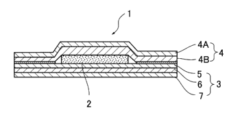
example, oxygen and air) in an oxidizing gas atmosphere or by
blowing an oxidizing gas or other means, thereby partially
oxidizing the iron component. A method for determining a
degree of oxidation is not limited. Examples thereof include
a method in which a degree of contact of the mixture or heat
generating composition with an oxidizing gas is determined by
the water mobility value of the mixture or heat generating
composition, the contact time with the oxidizing gas, the
exothermic temperature rise rate at the time of contact, the
exothermic temperature at the time of contact, the maximum
exothermic temperature at the time of contact, a prescribed
temperature as dropped after reaching the maximum exothermic
temperature at the time of contact, or a combination thereof,
thereby determining a degree of oxidation.
For examples, the following methods are preferable.
(1) A heat generating composition having a water
mobility value of not more than 20 (for example, less than 0. 01
or from 0.01 to 20) is exposed to air while fluidizing by
stirring or the like to cause self heat generation,
intercepted from air for a desired period of time until the
temperature exceeds a maximum exothermic temperature and then
returned to room temperature, thereby forming a heat
39
CA 02573812 2007-01-12
generating composition. In particular, a contact treatment
with an oxidizing gas by exposing a heat generating mixture
or heat generating composition having a water mobility value
of less than 0.01 to air while stirring, thereby causing self
heat generation is preferable.
(2) A heat generating composition having a water
mobility value exceeding 20 is brought into contact with air
and intercepted from air for a desired period of time, thereby
forming a heat generating composition.
(3) Water or a reaction accelerator aqueous solution is
added to the heat generating composition as obtained in either
one of (1) or (2), and the water content of the mixture is
adjusted, followed by mixing to form a heat generating
composition having a desired water mobility value. The weight
of the water or reaction accelerator aqueous solution to be
added for the purpose of adjusting the water content is not
limited. Examples thereof include a weight as reduced against
the weight of the mixture or heat generating composition prior
to exposing to air, namely prior to causing self heat
generation, or a weight corresponding to the weight exceeding
it. If desired, the temperature state of the mixture and the
heat generating composition may be controlled prior to the
contact treatment and/or at the time of contact treatment by
warming the mixture, warming the heat generating composition
and warming a reaction vessel, heat insulation, cooling, or
CA 02573812 2007-01-12
a combination thereof. In this way, a heat generating
composition having remarkably excellent exothermic rising
properties can be obtained.
[0035]
As the "oxidizing gas" as referred to herein, any
substance may be employed so far as it is gaseous and oxidizing.
Examples thereof include an oxygen gas, air, and a mixed gas
of an inert gas (for example, a nitrogen gas, an argon gas,
and a helium gas) and an oxygen gas. As the mixed gas, it is
preferable that it contains 10 % or more of an oxygen gas. Of
these, air is especially preferable.
So far as the atmosphere of the contact treatment region
does not become deficient in oxygen and an oxidation reaction
of the iron component is caused, a temperature of the oxidizing
gas, a temperature of the contact treatment and a time of the
contact treatment are not limited and may be properly
determined depending upon the desire. The temperature of the
oxidizing gas is preferably from 0 to 200 C, more preferably
from 10 to 150 C, and further preferably from 20 to 100 C;
and the treatment time is preferably from one second to 10
minutes, more preferably from 5 seconds to 7 minutes, and
further preferably from 15 seconds to 5 minutes. In the step,
it is preferable that the reaction time is short.
The amount of the oxidizing gas to be used may be
adjusted depending upon the kind of the oxidizing gas, the kind
41
CA 02573812 2007-01-12
and particle size of the iron powder, the water content, the
treatment temperature, the treatment method, and the like. In
the case of using air, the amount of air is preferably from
1 to 1,000 liters/min per 200 g of the iron powder under one
atmosphere at 100 C. In the case of other oxidizing gas, the
amount of the oxidizing gas may be reduced into the
concentration of oxygen on the basis of the case of air.
If desired, an acidic substance or a peroxide may be
added at the time of the contact treatment with an oxidizing
gas. Examples of the peroxide include hydrogen peroxide and
ozone. In the case of carrying out the treatment with an
oxidizing gas in an open system, the treatment may be carried
out in a lid-free vessel or in a manner such that an oxidizing
gas such as air comes into a vessel through an air-permeable
sheet-like material such as non-woven fabrics.
[0036]
The "heat generating mixture" as referred to herein is
a material obtained by subjecting a reaction mixture
containing, as essential components, an iron powder, a carbon
component, a reaction accelerator and water and having a water
content of from 1 to 20 % by weight and a water mobility value
of less than 0.01 to a contact treatment with an oxidizing gas
under fluidization, thereby regulating a temperature rise at
1 C or higher within 10 minutes. So far as some change is
caused in the reaction mixture by the contact treatment with
42
CA 02573812 2007-01-12
an oxidizing gas, the iron powder is not always required to
be oxidized. However, it is preferable that the iron powder
is oxidized. In that case, it is preferable that the iron
powder becomes an active iron powder.
[0037]
The fixing means is not limited so far as it has
capability for fixing a thermal packaging body for joint
surroundings or a material having an exothermic part to a
prescribed part.
As the fixing means, an adhesive layer, a hook and eye,
a hook and button, a hook and loop fastener such as Velcro,
a magnet, a band, a string, and combination thereof can be
arbitrarily used.
Incidentally, in the case of a band, fixing means for
adjustment may be further constructed by a combination of a
hook and loop fastener and an adhesive layer.
Here, the "hook and loop fastener" as referred to herein
has a fastening function by a combination of a loop as a female
fastener with a male fastener capable of fastening the female
fastener thereto, which is known as trade names such as Magic
Tape (a registered trademark), Magic Fastener (a registered
trademark), Velcro Fastener, and Hook and Loop Tape. Examples
of the material having a loop function include non-woven
fabrics and woven fabrics of napped or hole-containing yarns.
Such a material having a loop function (female fastener
43
CA 02573812 2007-01-12
function) may be covered on the surface of a paddling forming
the band, or the band may be constructed of such a material
itself. Although the hook member which is the male fastener
member is not particularly limited, examples thereof include
hook members formed of a polyolefin based resin (for example,
polyethylene and polypropylene), a polyamide, a polyester,
etc. Although the shape of the hook is not particularly
limited, a hook having a cross-sectional shape such as an I
type, an inverted L type, an inverted J type, and a so-called
mushroom type is preferable because it is easily hooked by the
loop and does not give an extreme stimulus to the skin.
Incidentally, the hook may be adhered to the entire area of
a fastening tape, and only the hook may be used as a fastening
tape while omitting a tape substrate.
The adhesive layer may contain at least one member
selected from additional components consisting of a water
retaining agent, a water absorptive polymer, a pH adjusting
agent, a surfactant, an organosilicon compound, a hydrophobic
polymer compound, a pyroelectric substance, an antioxidant,
an aggregate, a fibrous material, a moisturizer, a functional
substance, and a mixture thereof.
The adhesive of the invention is classified into a
non-hydrophilic adhesive, a mixed adhesive, and a hydrophilic
adhesive (for example, a gel).
The adhesive constituting the adhesive layer is not
44
CA 02573812 2007-01-12
limited so far as it has an adhesive strength necessary for
adhering to the skin or clothes. Adhesives of every form such
as a solvent based adhesive, an aqueous adhesive, an emulsion
type adhesive, a hot melt type adhesive, a reactive adhesive,
a pressure-sensitive adhesive, a non-hydrophilic adhesive,
and a hydrophilic adhesive are employable.
The adhesive layer includes one layer of a
non-hydrophilic adhesive constituted of the non-hydrophilic
adhesive and non-hydrophilic adhesive layers constituted of
the non-hydrophilic adhesive.
It is to be noted that a material whose water absorption
properties are improving by containing a water absorptive
polymer or a water retaining agent in the non-hydrophilic
adhesive layer is dealt as the non-hydrophilic adhesive layer.
A hot melt based adhesive may be provided between the
hydrophilic adhesive layer and a substrate or a covering
material.
Furthermore, in the case where the hydrophilic adhesive
is provided in a thermal packaging body for joint surroundings,
there is no limitation. After seal treating a thermal
packaging body for joint surroundings, a hydrophilic adhesive
layer may be provided in the thermal packaging body for joint
surroundings.
Furthermore, the adhesive layer may or may not have air
permeability and may be properly selected depending upon the
CA 02573812 2007-01-12
utility. With respect to the air permeability, the adhesive
layer may be air-permeable as a whole. Examples thereof
include an adhesive layer having air permeability as a whole
of a region in which an adhesive is partially present and a
portion where no adhesive is present is partially present.
In laminating an adhesive on an air-permeable substrate
and/or a covering material in a stratiform state as it is,
examples of a method for keeping its air permeability include
a method in which an adhesive layer is partially laminated by
printing or transferring an adhesive, thereby forming a
non-laminated part as an air-permeable part; a method in which
an adhesive is transferred in one direction while drawing a
circle in a filament-like form or properly moved in the
two-dimensional directions by transferring in a zigzag manner,
whereby a space of the filament-like adhesive keeps air
permeability or moisture permeability or the adhesive is
foamed; and a method for forming a layer by a melt blow system.
Examples of the adhesive which constitutes the
non-hydrophilic adhesive layer include acrylic adhesives,
polyvinyl acetate based adhesives (for example, vinyl acetate
resin based emulsions and ethylene-vinyl acetate resin based
holt melt adhesives), polyvinyl alcohol based adhesives,
polyvinyl acetal based adhesives, vinyl chloride based
adhesives, polyamide based adhesives, polyethylene based
adhes-ives, cellulose based adhesives, chloroprene (neoprene)
46
CA 02573812 2007-01-12
based adhesives, nitrile rubber based adhesives, polysulfide
based adhesives, butyl rubber based adhesives, silicone
rubber based adhesives, styrene based adhesives (for example,
styrene based hot melt adhesives), rubber based adhesives, and
silicone based adhesives. Of these, rubber based adhesives,
acrylic adhesives, and adhesives containing a hot melt based
polymer substance for the reasons that they are high in the
adhesive strength, are cheap, are good in long-term stability,
and are small in reduction of the adhesive strength even by
providing heat.
In addition to the base polymer, if desired, the
adhesive may be compounded with other components such as
tackifiers (for example, petroleum resins represented by
rosins, chroman-indene resins, hydrogenated petroleum resins,
maleic anhydride-modified rosins, rosin derivatives, and C-5
based petroleum resins), phenol based tackifiers (especially,
tackifiers having an aniline point of not higher than 50 C;
for example, terpene phenol based resins, rosin phenol based
resins, and alkylphenol based resins), softeners (for example,
coconut oil, castor oil, olive oil, camellia oil, and liquid
paraffin), softeners, anti-aging agents, fillers, aggregates,
adhesion adjusting agents, adhesion modifiers, coloring
agents, anti-foaming agents, thickeners, and modifiers,
thereby improving performance such as an improvement in
adhesion to nylon-made clothes and mixed yarn clothes.
47
CA 02573812 2007-01-12
Examples of the hot melt based adhesive include known
hot melt based adhesives imparted with adhesion. Specific
examples thereof include styrene based adhesives made of, as
a base polymer, an A-B-A type block copolymer (for example,
SIS, SBS, SEBS, and SIPS) , vinyl chloride based adhesives made
of, as a base polymer, a vinyl chloride resin, polyester based
adhesives made of, as a base polymer, a polyester, polyamide
based adhesives made of, as a base polymer, a polyamide,
acrylic adhesives made of, as a base polymer, an acrylic resin,
polyolefin based adhesives made of, as a base polymer, a
polyolefin (for example, polyethylene, super low density
polyethylene, polypropylene, ethylene-(x-olefin copolymers,
and ethylene-vinyl acetate copolymers), 1,2-polybutadiene
based adhesives made of, as a base polymer, 1,2-polybutadiene,
and polyurethane based adhesives made of, as a base polymer,
polyurethane; adhesives made of a modified body of the
foregoing adhesive whose adhesion is improved or whose
stability is changed; and mixtures of two or more kinds of
these adhesives. Adhesive layers constituted of a foamed
adhesive and adhesive layers constituted of a crosslinked
adhesive can also be employed.
The non-aromatic hot melt based adhesive is not limited
so far as it is made of, as a base polymer, a hot melt based
adhesive not containing an aromatic ring. Examples thereof
include olefin based hot melt based adhesives and acrylic hot
48
CA 02573812 2007-01-12
melt based adhesives. As the non-aromatic polymer which is
the base polymer not containing an aromatic ring, there are
enumerated polymers or copolymers of an olefin or a diene.
Examples thereof include olefin polymers. The olefin polymer
includes polymers or copolymers of ethylene or an a-olefin.
Also, polymers resulting from adding a diene (for example,
butadiene and isoprene) as other monomer thereto may be
employed.
The a-olefin is not limited so far as it is a monomer
having a double bond in the terminal thereof. Examples thereof
include propylene, butene, heptane, hexene, and octene.
The "aromatic hot melt based adhesive" as referred to
herein is a hot melt based adhesive whose base polymer contains
an aromatic ring. Examples thereof include styrene based hot
melt based adhesives represented by A-B-A type block
copolymers.
In the foregoing A-B-A type block copolymers, the A
block is a non-elastic polymer block made of a monovinyl
substituted aromatic compound A such as styrene and
methylstyrene; and the B block is an elastic polymer block made
of a conjugated diene such as butadiene and isoprene. Specific
examples thereof include a styrene-butadiene-styrene block
copolymer (SBS), a styrene-isoprene-styrene block copolymer
(SIS), and hydrogenated types thereof (for example, SEBS and
SIPS), and mixtures thereof.
49
CA 02573812 2007-01-12
As a countermeasure for preventing a lowering of
adhesive strength caused due to an increase of water of the
non-hydrophilic adhesive layer, an adhesive layer obtained by
further compounding a water absorptive polymer in the
non-hydrophilic adhesive can be used.
The hydrophilic adhesive which constitutes the
hydrophilic adhesive layer is not particularly limited so far
as it contains a hydrophilic polymer or a water-soluble
polymer as the major component, has adhesion and is
hydrophilic as an adhesive.
Examples of the constitutional components of the
hydrophilic adhesive include hydrophilic polymers (for
example, polyacrylic acid), water-soluble polymers (for
example, poly(sodium acrylate) and polyvinylpyrrolidone),
crosslinking agents (for example, dry aluminum hydroxide and
meta-silicic acid aluminic acid metal salts), softeners (for
example, glycerin and propylene glycol), higher hydrocarbons
(for example, soft liquid paraffin and polybutene), primary
alcohol fatty acid esters (for example, isopropyl myristate),
silicon-containing compounds (for example, silicone oil),
fatty acid glycerin esters (for example monoglycerides), oily
components (for example, vegetable oils such as olive oil),
antiseptics (for example, methyl p-hydroxybenzoate and propyl
p-hydroxybenzoate), solubilizing agents (for example,
N-methyl-2-pyrrolidone), thickeners (for example, carboxy-
CA 02573812 2007-01-12
methyl cellulose), surfactants (for example, polyoxyethylene
hardened castor oil and sorbitan fatty acid esters),
hydroxycarboxylic acid (for example, tartaric acid),
excipients (for example, light silicic anhydride, water
absorptive polymers, and kaolin) , moisturizers (for example,
D-sorbitol), stabilizers (for example, sodium edetate,
p-hydroxybenzoic acid esters, and tartaric acid),
crosslinking type water absorptive polymers, boron compounds
(for example, boric acid), and water. They may be used as an
arbitrary combination.
A temporary adhering seal part is formed via a sticky
layer. An adhesive which constitutes the sticky layer is a
layer formed of a polymer composition which is tacky at the
normal temperature and is not limited so far as it can be heat
sealed after temporary adhesion.
Furthermore, the foregoing adhesives of the sticky
layer can be used as the adhesive which constitutes the sticky
layer as used for temporary adhesion. Of these,
non-hydrophilic adhesives are preferable. With respect to the
adhesive constituting the adhesive layer, it is preferable
that the adhesive is well compatible with a heat seal material
constituting a heat seal and that a melting point of the base
polymer of the adhesive is not higher than a melting point of
the heat seal material. Hot melt based adhesives are
especially preferable for hot melt based bonding agents.
51
CA 02573812 2007-01-12
Furthermore, in the case where the heat seal material is an
olefin based raw material, preferred examples thereof include
olefin based adhesives.
A bonding layer for fixing the air permeability
adjusting material is constituted of a bonding agent or an
adhesive which is usually used. In particular, an adhesive
is useful, and the foregoing adhesives for constituting the
adhesive layer can be used.
Furthermore, a method for providing a bonding layer is
not limited so far as the air permeability adjusting material
can be fixed. The bonding layer may be entirely provided or
partially or intermittently provided. Examples of its shape
include various shapes such as a network-like shape, a
stripe-like shape, a dot-like shape, and strip-like shape.
Furthermore, in the case where an adhesive layer is
employed as the hydrophilic adhesive layer, if there is a
difference in a water retaining force between the hydrophilic
adhesive layer and the heat generating composition molded body,
transfer of water occurs via a packaging material present
therebetween such as a substrate, thereby causing
in-conveniences against the both. In particular, the transfer
of water occurs during the storage. In order to prevent this,
it is preferable that the packaging material present
therebetween at least has a moisture permeability of not more
than 2 g/m2/day in terms of a moisture permeability according
52
CA 02573812 2007-01-12
to the Lyssy method. By using this, in the case where the heat
generating body is accommodated in an outer bag as an
air-impermeable accommodating bag and stored, the transfer of
water can be prevented.
In the case where a hydrophilic adhesive layer is used
as the adhesive layer, the moisture permeability of a
moisture-proof packaging material provided between the heat
generating composition molded body and the hydrophilic
adhesive layer is not limited so far as the transfer of water
can be prevented within the range where the exothermic
performance is not affected. The moisture permeability
according to the Lyssy method is usually not more than 2
g/m2/day, preferably not more than 1.0 g/m2/day, more
preferably not more than 0.5 g/m2/day, and further preferably
from 0.01 to 0.5 g/m2/day. These values are a value under a
condition under an atmospheric pressure at 40 C and 90 % RH.
Incidentally, the moisture-proof packaging material can be
used as a substrate or a covering material and may be laminated
singly on a substrate, a covering material, or the like.
The moisture-proof packaging material is not limited so
far as the transfer of water between the heat generating
composition molded body and the hydrophilic adhesive layer can
be prevented. Examples thereof include metal vapor deposited
films, vapor deposited films of a metal oxide, metal
foil-laminated films, EVOH (ethylene/vinyl alcohol copolymer
53
CA 02573812 2007-01-12
or ethylene/vinyl acetate copolymer saponified product) based
films, biaxially stretched polyvinyl alcohol films, poly-
vinylidene chloride coated films, polyvinylidene chloride
coated films obtained by coating polyvinylidene chloride on
a substrate film (for example, polypropylene), metal foils
such as an aluminum foil, air-impermeable packaging materials
obtained by vapor depositing or sputtering a metal (for
example, aluminum) on a polyester film substrate, and
packaging laminates using a transparent barrier film of a
structure in which silicon oxide or aluminum oxide is provided
on a flexible plastic substrate. The air-impermeable
packaging materials which are used in the outer bag, etc. can
also be used.
Furthermore, packaging materials such as
moisture-proof packaging materials as described in
JP-A-2002-200108, the disclosures of which can be
incorporated herein by reference, can be used.
In the case of using a water-containing hydrophilic
adhesive (for example, a gel) in the adhesive layer, in order
to adjust the moisture equilibrium between the heat generating
composition and the adhesive layer, the content of a reaction
accelerator (for example, sodium chloride) or a substance
having a water holding power (for example, a water absorptive
polymer) in the heat generating composition may be adjusted
within the range of from 10 to 40 % by weight, preferably from
54
CA 02573812 2007-01-12
15 to 40 % by weight, and more preferably from 15 to 30 % by
weight based on the heat generating composition.
Furthermore, as the adhesive having good moisture
permeability and low stimulation to the skin, water-contain-
ing adhesives (for example, hydrophilic adhesives and gels)
as described in JP-A-10-265373 and JP-A-9-87173, adhesives
which can be subjected to hot melt coating as described in
JP-A-6-145050 and JP-A-6-199660, and rubber based adhesives
as described JP-A-10-279466 and JP-A-10-182408, the
disclosures of which are totally incorporated herein by
reference, are useful.
[0038]
The water retaining agent is not limited so far as it
is able to retain water. Examples thereof include porous
materials derived from plants having high capillary function
and hydrophilicity such as wood meal, pulp powder, active
carbon, saw dust, cotton cloth having a number of cotton fluffs,
short fiber of cotton, paper dust, and vegetable materials,
water-containing magnesium silicate based clay minerals such
as active clay and zeolite, pearlite, vermiculite, silica
based porous substances, coralline stone, and volcanic ash
based substances (for example, terraballoon, shirasu balloon,
and taisetsu balloon) . In order to increase a water retaining
ability and enhance a shape holding ability of such a water
retaining agent, the water retaining agent may be subjected
CA 02573812 2007-01-12
to a processing treatment such as baking and/or pulverization.
The water absorptive polymer is not particularly
limited so far as it is a resin having a crosslinking structure
and having a water absorption magnification of ion-exchanged
water of 3 times or more of the dead weight. Furthermore, a
water absorptive polymer the surface of which is crosslinked
may be employed. Conventionally known water absorptive
polymers and commercial products may also be employed.
Examples of the water absorptive polymer include
poly(meth)acrylic acid crosslinked materials, poly(meth)-
acrylic acid salt crosslinked materials, sulfonic group-con-
taining poly(meth)acrylic ester crosslinked materials,
polyoxyalkylene group-containing poly(meth)acrylic ester
crosslinked materials, poly(meth)acrylamide crosslinked
materials, crosslinked materials of a copolymer of a
(meth)acrylic acid salt and a (meth)acrylamide, crosslinked
materials of a copolymer of a hydroxyalkyl (meth)acrylate and
a (meth)acrylic acid salt, polydioxolane crosslinked
materials, crosslinked polyethylene oxide, crosslinked
polyvinylpyrrolidone, sulfonated polystyrene crosslinked
materials, crosslinked polyvinylpyridine, saponification
products of a starch-poly(meth)acrylonitrile graft copolymer,
starch-poly(meth)acrylic acid (salt) graft crosslinked
copolymers, reaction products of polyvinyl alcohol and maleic
anhydride (salt), crosslinked polyvinyl alcohol sulfonic acid
56
CA 02573812 2007-01-12
salts, polyvinyl alcohol-acrylic acid graft copolymers, and
polyisobutylene maleic acid (salt) crosslinked polymers.
These water absorptive polymers may be used alone or in
combination with two or more kinds thereof.
Of these water absorptive polymers, water absorptive
polymers having biodegradation properties are not limited so
far as they are a biodegradable water absorptive polymer.
Examples thereof include polyethylene oxide crosslinked
materials, polyvinyl alcohol crosslinked materials,
carboxymethyl cellulose crosslinked materials, alginic acid
crosslinked materials, starch crosslinked materials,
polyamino acid crosslinked materials, and polylactic acid
crosslinked materials.
The pH adjusting agent is not limited so far it is able
to adjust the pH. Examples thereof include alkali metal weak
acid salts and hydroxides and alkaline earth metal weak acid
salts and hydroxides such as Na2CO3, NaHCO3, Na3POq, Na2HPOq,
Na5P3O1o, NaOH, KOH, Ca (OH) zr Mg (OH) 2, and Ca3 (P04) 2.
The surfactant includes anionic surfactants, cationic
surfactants, nonionic surfactants, and ampholytic sur-
factants. Especially, nonionic surfactants are preferable,
and examples thereof include polyoxyethylene alkyl ethers,
alkylphenol=ethylene oxide adducts, and higher alcohol
phosphoric acid esters.
The hydrophobic polymer compound is not limited so far
57
CA 02573812 2007-01-12
as it is a polymer compound having a contact angle with water
of 40 or more, preferably 50 or more, and more preferably 60
or more in order to improve the draining in the composition.
The shape of the hydrophobic polymer compound is not limited,
and examples thereof include powdery, particulate, granular,
and tablet shapes. Examples of the hydrophobic polymer
compound include polyolefins such as polyethylene and
polypropylene, polyesters, and polyamides.
The pyroelectric substance is not limited so far as it
has pyroelectricity. Examples thereof include tourmaline,
hemimorphic ores, and pyroelectric ores. Tourmaline or
achroite which is a kind of tourmaline is especially
preferable. Examples of the tourmaline include dravite,
schorl, and elbaite.
The aggregate is not limited so far as it is useful as
a filler and/or is useful for making the heat generating
composition porous. Examples thereof include fossilized
coral (for example, coral fossil and weathered coral fossil) ,
bamboo charcoal, bincho charcoal, silica-alumina powders,
silica-magnesia powders, kaolin, crystalline cellulose,
colloidal silica, pumice, silica gel, silica powders, mica
powders, clays, talc, synthetic resin powders or pellets,
foamed synthetic resins such as foamed polyesters or
polyurethanes, diatomaceous earth, alumina, and cellulose
powder. Incidentally, it is to be noted that kaolin and
58
CA 02573812 2007-01-12
crystalline cellulose are not contained in the heat generating
composition of the invention.
The fibrous material is an inorganic fibrous material
and/or an organic fibrous material. Examples thereof include
rock wool, glass fibers, carbon fibers, metal fibers, pulps,
papers, non-woven fabrics, woven fabrics, natural fibers such
as cotton and hemp, regenerated fibers such as rayon,
semi-synthetic fibers such as acetates, synthetic fibers, and
pulverized products thereof.
The moisturizer is not limited so far as it is able to
hold moisture. Examples thereof include hyaluronic acid,
collagen, glycerin, and urea.
The functional substance is not limited so far as it has
any function. Examples thereof include at least one kind
selected from aromatic compounds, vegetable extracts, crude
drugs, perfumes, slimming agents, analgesics, blood
circulation promoters, swelling improvers, antibacterial
agents, sterilizers, mold inhibitors, odor eaters, deodorants,
percutaneously absorptive drugs, fat-splitting components,
minus ion generators, far infrared ray radiants, magnetic
bodies, fomentations, cosmetics, bamboo vinegar, and wood
vinegar.
Specific examples thereof include aromatic compounds
(for example, menthol and benzaldehyde), vegetable extracts
(for example, mugwort extract) , crude drugs (for example,
59
CA 02573812 2007-01-12
moxa), perfumes (for example, lavender and rosemary),
slimming agents (for example, aminophylline and tea extract) ,
analgesic drugs (for example, indomethacin and dl-camphor),
blood circulation promoters (for example, acidic
mucopolysaccharide and chamomile), swelling improvers (for
example, horse chestnut extract and flavone derivatives),
fomentations (for example, aqueous boric acid, physiological
saline, and aqueous alcohols), fat-splitting components (for
example, jujube extract, caffeine, and tonalin), cosmetics
(for example, aloe extracts, vitamin preparations, hormone
preparations, anti-histamines, and amino acids), anti-
bacterial agents and sterilizers (for example, carbolic acid
derivatives, boric acid, iodine preparations, invert soaps,
salicylic acid based substances, sulfur, and antibiotics),
and mold inhibitors.
The percutaneously absorptive drug is not particularly
limited so far as it has percutaneous absorption. Examples
thereof include corticosteroids, anti-inflammatory drugs,
hypertension drugs, anesthetics, hypnotic sedatives,
tranquillizers, antibacterial substances, antifungal
substances, skin stimulants, inflammation inhibitors,
anti-epileptics, analgesics, antipyretics, anesthetics, mold
inhibitors, antimicrobial antibiotics, vitamins, antiviral
agents, swelling improvers, diuretics, antihypertensives,
coronary vasodilators, anti-tussive expectorants, slimming
CA 02573812 2007-01-12
agents, anti-histamines, antiarrhythmic agents, cardiotonics,
adrenocortical hormones, blood circulation promoters, local
anesthetics, fat-splitting components, and mixtures thereof.
However, it should not be construed that the invention is
limited thereto. These drugs are used singly or in admixture
of two or more kinds thereof as the need arises.
The content of such a functional substance is not
particularly limited so far as it falls within the range where
the effect of a medicine can be expected. However, from the
viewpoints of adhesive strength as well as pharmacological
effect and economy, the content of the functional substance
is preferably from 0.01 to 25 parts by weight, and more
preferably from 0.5 to 15 parts by weight based on 100 parts
by weight of the adhesive.
Furthermore, a method for providing the adhesive layer
is not limited so far as a thermal packaging body for joint
surroundings can be fixed. The adhesive layer may be entirely
provided or partially or intermittently provided. Examples
of its shape include various shapes such as a network-like
shape, a stripe-like shape, a dot-like shape, and strip-like
shape.
[0039]
Further, the shape of the heat generating body is not
limited but can be selected from the group consisting of a
rectangular shape, a circular shape, an elliptical shape, a
61
CA 02573812 2007-01-12
polygonal shape, a broad bean-like shape, an eye mask-like
shape, a paper lantern-like shape, a cocoon-like shape, a
gourd-like shape, a rectangular shape with rounded corners,
a square shape with rounded corners, an egg-like shape, a
boomerang-like shape, a comma-shaped bead-like shape, a
wing-like shape, a nose-like shape, a star-like shape, and a
foot-like shape.
[0040]
Furthermore, the heat generating body or accommodating
bag can be provided with at least one member of characters,
designs, symbols, numerals, patterns, photographs, pictures,
and colors in at least a part thereof.
[0041]
The heat generating body of the invention is able to give
various shapes, thicknesses and temperature zones and
therefore, can be used for various utilities such as use for
a joint, facial esthetic use, use for eyes, slimming use, use
for heating or warming a dripping solution, use for a wet
compress pack, use for a medical body warmer, use for a neck,
use for a waist, use for a mask, use for a glove, use for
hemorrhage, use for relaxation of symptoms such as shoulder
pain, muscular pain, and menstrual pain, use for a cushion,
use for heating or warming a human body during the operation,
use for a thermal sheet, use for thermally volatilizing an
aroma, use for an abdomen, insecticidal use by thermal
62
CA 02573812 2007-01-12
volatilization, and use for treating cancer in addition to
common warming of a human body. In addition, the heat
generating body of the invention can be used for heating or
warming machines, pets, etc.
[0042]
For example, in the case of using for relaxation of
symptoms, the heat generating body of the invention is applied
directly in a necessary site of the body or indirectly via a
cloth, etc. Furthermore, in the case of using for heating or
warming a human body during the operation, a method for using
the heat generating body of the invention includes the
following methods.
(1) The heat generating body is directly applied to a
body requiring heating or warming.
(2) The heat generating body is fixed on a covering, etc.
and covered on the body.
(3) The heat generating body is fixed on a cushion to
be placed beneath the body, etc.
(4) The heat generating body is used as a covering or
a cushion which is a product having the heat generating body
provided therein in advance.
Incidentally, examples of the pain of muscles or bones
include acute muscle pain, acute bone pain, acute reference
pain, previous muscle pain, previous bone pain, chronic
reference pain, and join pain of knee, elbow, etc.
63
CA 02573812 2007-01-12
The holding time is not limited but is preferably from
20 seconds to 24 hours, more preferably from one hour to 24
hours, and further preferably from 8 hours to 24 hours.
The holding temperature is preferably from 30 to 50 C,
more preferably from 32 to 50 C, further preferably from 32
to 43 C, still further preferably from 32 to 41 C, and even
further preferably from 32 to 39 C.
[0043]
The invention will be specifically described below with
reference to the Examples, but it should not be construed that
the invention is limited thereto.
[Brief Description of the Drawings]
[0044]
[Fig. 1] is a plan view of an embodiment of the heat
generating body of the invention.
[Fig. 2] is a cross-sectional view along the line Z-Z
of the same.
[Fig. 3] is a diagram of exothermic characteristics of
the heat generating composition of Example 1 and Comparative
Example 1.
[Fig. 4] is a diagram of exothermic characteristics of
the heat generating body of Examples 2 and Comparative Example
2.
[Fig. 5] is a plan view of the heat generating body of
Example 3.
64
CA 02573812 2007-01-12
[Fig. 6] is a plan view of a filter paper for the
measurement of water mobility value in the invention.
[Fig. 7] is an oblique view for explaining the
measurement of water mobility value in the invention.
[Fig. 8] is a cross-sectional view for explaining the
measurement of water mobility value in the invention.
[Fig. 9] is a cross-sectional view for explaining the
measurement of water mobility value in the invention.
[Fig. 10] is a plan view of a filter paper after carrying
out the measurement of water mobility value in the invention.
[Description of Reference Numerals and Signs]
[0045]
1: Heat generating body
1C: Sectioned part (seal part)
2: Heat generating composition molded body
2': Heat generating composition molded body
(sectional exothermic part)
3: Substrate
4: Covering material
6: Adhesive layer
7: Separator
8: Perforation
9: Pushing plate
10: Flat plate
11: Non-water absorptive film (polyethylene film,
CA 02573812 2007-01-12
etc.)
12: Filter paper in which eight lines are drawn
radiating from the central point with an interval of 45
13: Die plate
14: Hole
15: Sample
16: Stainless steel plate
17: Distance to the oozed-out locus of water or
aqueous solution
18: Position corresponding to a hollow cylindrical
hole on filter paper
[Examples]
[0046]
(Example 1)
A stirring type batchwise oxidizing gas contact
treatment device consisting of a mixer equipped with a rotary
blade for stirring was used as an oxidizing gas contact
treatment device, and air was used as an oxidizing gas.
First of all, a reaction mixture consisting of 100 parts
by weight of a reduced iron powder (particle size: not more
than 300 m), 3.5 parts by weight of active carbon (particle
size: not more than 300 m), and 10 parts by weight of 11 %
salt water and having a water mobility value of less than 0.01
was charged in the stirring type batchwise oxidizing gas
contact treatment device. Next, the upper portion of the
66
CA 02573812 2007-01-12
oxidizing gas contact treatment device was opened to air, the
reaction mixture was subjected to self heat generation with
stirring under circumstances at 20 C, and at a point of time
when a temperature rise of the reaction mixture reached 10 C,
the reaction mixture was sealed in an air-impermeable
accommodating bag and then cooled to room temperature, thereby
obtaining a heat generating mixture. With respect to the iron
powder of the heat generating mixture, a thickness of the
resulting iron oxide film on the surface of the iron powder
was measured by the Auger electron spectroscopy. The
thickness of the iron oxide film was 100 nm. Next, 11 % salt
water was mixed in the contact treated reaction mixture to
obtain a heat generating composition having a water mobility
value of 10.
[0047]
(Comparative Example 1)
A heat generating composition having a water mobility
value of 10 was prepared in the same manner as in Example 1,
except that the contact treatment with an oxidizing gas was
not carried out.
[0048]
Each of the heat generating compositions as obtained in
Example 1 and Comparative Example 1 was subjected to an
exothermic test, thereby obtaining the results as shown in Fig.
3. It is noted that Comparative Example 1 is deteriorated in
67
CA 02573812 2007-01-12
exothermic rising properties.
[0049]
(Example 2)
A stirring type batchwise oxidizing gas contact
treatment device consisting of a mixer equipped with a rotary
blade for stirring was used as an oxidizing gas contact
treatment device, and air was used as an oxidizing gas. First
of all, a reaction mixture consisting of 100 parts by weight
of a reduced iron powder (particle size: not more than 300 m)
having a thickness of an iron oxide film of less than 20 nm,
3.5 parts by weight of active carbon (particle size: not more
than 300 m) , 2. 3 parts by weight of a wood meal (particle size:
not more than 300 m) , 2. 3 parts by weight of a water absorptive
polymer (particle size: not more than 300 m), 0.2 parts by
weight of calcium hydroxide, 0.7 parts by weight of sodium
sulfite, and 10 parts by weight of 11 % salt water and having
a water mobility value of less than 0.01 was charged in the
stirring type batchwise oxidizing gas contact treatment
device. Next, the upper portion of the oxidizing gas contact
treatment device was opened to air, the reaction mixture was
subjected to self heat generation with stirring under
circumstances at 25 C, and at a point of time when a
temperature rise of the reaction mixture reached 15 C, the
reaction mixture was sealed in an air-impermeable
accommodating bag and then cooled to room temperature, thereby
68
CA 02573812 2007-01-12
obtaining a heat generating mixture. With respect to the iron
powder of the heat generating mixture, a thickness of the
resulting iron oxide film on the surface of the iron powder
was measured by the Auger electron spectroscopy. The
thickness of the iron oxide film was 200 nm. Next, 11 % salt
water was mixed in the contact treated reaction mixture to
obtain a heat generating composition having a water mobility
value of 8.
[0050]
This heat generating composition was subjected to an
exothermic test of heat generating composition. As a result,
the temperature was about 50 C (an average value of five
samples) after 3 minutes.
Furthermore, the heat generating composition was tested
for moldability. As a result, even after separating a trimming
die from a heat generating composition molded body, the heat
generating composition molded body was free from a loss of
shape, and collapsed pieces of the heat generating composition
molded body were not generated in the surroundings of the heat
generating composition molded body.
[0051]
(Example 3)
As illustrated in Figs. 1 and 2, by using the heat
generating composition of Example 2 and an air-impermeable
substrate 3 in which an adhesive layer 6 provided with a
69
CA 02573812 2007-01-12
separator 7 was provided on a polyethylene film 5, a heat
generating composition molded body 2 as obtained by molding
the foregoing heat generating composition by force-through
molding using a trimming die having a rectangular cavity of
2 mm in thickness, 110 mm in length and 80 mm in width was
laminated on the polyethylene film 5. In addition, an
air-permeable covering material 4 made of a laminate of a
nylon-made non-woven fabric 4A and a porous polyethylene film
4B was superimposed thereon such that the surface of the
polyethylene film 5 and the surface of the polyethylene-made
porous film 4B were brought into contact with each other. The
surroundings were heat sealed in a seal width of 8 mm and then
cut to produce a rectangular flat heat generating body 1 of
130 mm in length, 100 mm in width and 8 mm in seal width. Even
after separating the trimming die from the heat generating
composition molded body 2, the laminate was free from a loss
of shape, and collapsed pieces of the heat generating
composition molded body were not generated in the surroundings
of the heat generating composition molded body. Also, sealing
could be completely carried out without causing incorporation
of collapsed pieces of the heat generating composition molded
body into the seal part, and seal failure did not occur.
Incidentally, the air permeability of the covering material
4 was 370 g/m2/24 hr in terms of a moisture permeability by
the Lyssy method.
CA 02573812 2007-01-12
[0052]
(Comparative Example 2)
A heat generating composition having a water mobility
value of 8 was prepared in the same manner as in Example 3,
except that the contact treatment with an oxidizing gas was
not carried out, and a heat generating body was obtained in
the same manner as in Example 4.
[0053]
With respect to Example 2 and Comparative Example 2, the
exothermic test of heat generating body was carried out. As
a result, as shown in Fig. 4, in the case of Example 2, the
temperature was 40 C after 10 minutes and 53 C after 30 minutes,
respectively. However, in the case of Comparative Example 2,
the temperature was 35 C after 10 minutes and 43 C after 30
minutes, respectively. The heat generating body using the
heat generating composition of the invention was excellent
with respect to the exothermic rising properties.
[0054]
(Example 4)
By using the heat generating composition of Example 2
and an air-impermeable substrate 3 in which an adhesive layer
6 provided with a separator 7 was provided on a polyethylene
film, a heat generating composition molded body 2' (sectional
exothermic part) of a rectangular parallelepiped of 2 mm in
thickness, 115 mm in length and 80 mm in width was molded by
71
CA 02573812 2007-01-12
force-through molding using a trimming die having a thickness
of 2 mm and comprising 9 square cavities having a length of
one side of 15 mm and laminated on the side of the polyethylene
film 5. In addition, an air-permeable covering material 4 made
of a laminate of a nylon-made non-woven fabric and a porous
polyethylene film was superimposed thereon such that the
surface of the polyethylene film and the surface of the porous
film were brought into contact with each other. The periphery
of the heat generating composition molded body 2' (sectional
exothermic part) was heat sealed in a seal width of 8 mm to
provide a seal part 1C, from which was then produced a
rectangular irregular heat generating body 1 of 135 mm in
length, 100 mm in width and 8 mm in seal width (see Fig. 5).
Incidentally, in Fig. 5, the numeral 8 represents a
perforation.
Furthermore, the air permeability of the covering
material 4 was 370 g/m2/24 hr in terms of a moisture
permeability by the Lyssy method. The heat generating body
was sealed and accommodated in an air-impermeable outer bag
and then allowed to stand at room temperature for 24 hours.
As a result of an exothermic test by the body, it was felt warm
after 3 minutes, and thereafter, the warmth was continued for
hours or more.
72