Note: Descriptions are shown in the official language in which they were submitted.
CA 02574009 2007-01-15
WO 2006/130465 PCT/US2006/020438
SYSTEM AND METHOD FOR ENLARGING AMPLITUDE MINIMA
IN A LINEAR MODULATION SIGNAL
FIELD OF THE INVENTION
[0001] The present invention relates generally to the field of communication
systems. In
particular, the present invention relates to the conditioning of linear
modulated signals,
such as multi-carrier signals including Scalable Advanced Modulation (SAM)
signals or
Orthogonal Frequency Division Multiplexing (OFDM) signals, used in digital
transmitters.
BACKGROUND OF THE INVENTION
[0002] In communication systems, a signal is modulated and amplified for
transmission
over communication channels. The signal is modulated using a modulator and
amplified
using a linear power amplifier. Different modulation techniques are developed
to convey
the signal across the communication channel. Examples of modulation techniques
include
amplitude modulation, phase modulation, and frequency modulation. Depending
upon the
modulation technique used, a resultant transmitted signal may have a varying
dynamic
range and a varying Peak to Average Power Ratio (PAPR). The dynamic range is
defined
as the ratio between the peak signal power and the minimum signal power. The
PAPR is
defined as the ratio between peak signal power and the average signal power.
The
dynamic range and the PAPR of the modulated signal affect the efficiency of
the linear
1
CA 02574009 2007-01-15
WO 2006/130465 PCT/US2006/020438
power amplifier. Efficiency of the linear power amplifier decreases as the
dynamic range,
the PAPR, or a combination of both, increases.
[0003] In other words, amplitude value of the peak signal and the minimum
signal affects
the efficiency of the linear power amplifier. Higher amplitude of the peak
signal, and
lower amplitude of the minimum signal reduce the efficiency of the linear
power
amplifier. Therefore, in order to increase the efficiency of the linear power
amplifier,
either the amplitude of the minimum signal may be enlarged, or the amplitude
of the peak
signal may be suppressed.
[0004] There are various methods that use suppression or enlargement of the
amplitude
of the pealc signal or minimum signal to improve the efficiency of the linear
power
amplifier. A window clipping scheme is one such method that uses suppression
of the
amplitude of the peak signal of a modulated signal to increase the efficiency
of the linear
power amplifier. On the other hand, a windowed minimum enlarger increases the
amplitude of the minimum signal. The windowed minimum enlarger is applied to
signals
having minimum amplitude values that are less than a predefined minimum
threshold
value. The windowed minimum enlarger function scales-up the amplitude of that
portion
of the signal.
[0005] Adjacent Channel Coupled Signal Power (ACCPR) is defined as the ratio
of the
signal power in the adjacent channel and the signal power in the main channel.
In order to
maintain a low ACCPR for a multi-carrier signal, both the window clipping and
the
2
CA 02574009 2007-01-15
WO 2006/130465 PCT/US2006/020438
windowed minimum enlarger have to be applied with a considerable window
length. The
windowed minimum enlarger is the same with the window clipping but clipping
the low
peak (or minimum) signal. For example, to maintain a low ACCPR a window size
of 19
samples is used in a High Performance Data (HPD) signal. This causes overlap
in the
samples of window clipping and the windowed minimum enlarger. Further, the
amplification factor for minimum enlargement is more than that used for peak
suppression. As a result of this overlap, the suppressed peak signals lying in
the
overlapping region are again increased by the windowed minimum enlarger, which
increases the Peak to Average Power Ratio (PAPR) again.
Accordingly, there is a need for an improved apparatus and technique for
conditioning a
linear modulation signal without interfering with peak suppression schemes.
BRIEF DESCRIPTION OF THE DRAWINGS
[0006] The present invention is illustrated by way of example and not
limitation in the
accompanying figures, in which like references indicate similar elements, and
in which:
[0007] FIG.1 is a block diagram of a digital transmitter in which various
embodiments of
the present invention are practiced;
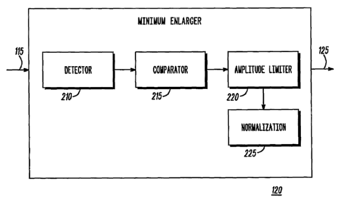
[0008] FIG. 2 is a block diagram of the sub-components of a minimum enlarger,
in
accordance with various embodiments of the present invention;
3
CA 02574009 2007-01-15
WO 2006/130465 PCT/US2006/020438
[0009] FIG. 3 is a flowchart for conditioning a linear modulation signal, in
accordance
with various embodiments of the present invention;
[0010] FIG. 4 illustrates an amplitude limiter function for minimum
enlargement, in
accordance with various embodiments of the invention;
[0011] FIG. 5 illustrates the effect of application of the amplitude limiter
function on an
Orthogonal Frequency Division Multiplexing (OFDM) signal, in accordance with
one of
the embodiments of the present invention; and
[0012] Skilled artisans will appreciate that elements in the figures are
illustrated for
simplicity and clarity and have not necessarily been drawn to scale. For
example, the
dimensions of some of the elements in the figures may be exaggerated relative
to other
elements to help to improve understanding of embodiments of the present
invention.
DETAILED DESCRIPTION OF THE DRAWINGS
[0013] In an embodiment, a digital transmitter includes a modulator and a
minimum
enlarger. The modulator provides a linear modulation signal, which is
characterized by its
amplitude and phase. The minimum enlarger receives the linear modulation
signal and
provides conditioning to the linear modulation signal. The minimum enlarger
includes a
detector, a comparator, and an amplitude limiter. The detector detects a local
minimum
amplitude value in the linear modulation signal. The comparator compares the
local
minimum amplitude value with a predetermined minimum amplitude threshold. The
amplitude limiter adjusts the local minimum amplitude value of the linear
modulation
4
CA 02574009 2007-01-15
WO 2006/130465 PCT/US2006/020438
signal to the predetermined minimum amplitude threshold if the local minimum
amplitude value is less than the predetermined minimum amplitude threshold.
Furthermore, the amplitude limiter retains the phase of the linear modulation
signal while
adjusting the linear modulation signal. As a result, the output of the
amplitude limiter is
an adjusted linear modulation signal.
[0014] In another embodiment, a method for enlarging local minimum amplitude
value in
a linear modulation signal characterized by its amplitude and phase is
provided. To
enlarge the local minimum amplitude value, first a predetermined minimum
amplitude
threshold is provided. Then, the local minimum amplitude value in a linear
modulation
signal is detected. After detecting the local minimum amplitude value, the
local minimum
amplitude value is compared with the predetermined minimum amplitude
threshold.
Further, the local minimum amplitude value is adjusted to the predetermined
minimum
amplitude threshold when the local minimum amplitude value is less than
predetermined
amplitude threshold. Furthermore, while adjusting the linear modulation
signal, the phase
of the linear modulation signal is retained.
[0015] Before describing in detail a method and system for enlarging local
minimum
amplitude values in a linear modulation signal, in accordance with the present
invention,
it should be observed that the present invention resides primarily in
combinations of
method steps and apparatus components related to a digital transmitter.
Accordingly, the
apparatus components and method steps have been represented, where
appropriate, by
conventional symbols in the drawings. These drawings show only the specific
details that
CA 02574009 2007-01-15
WO 2006/130465 PCT/US2006/020438
are pertinent for understanding the present invention, so as not to obscure
the disclosure
with details that will be apparent to those with ordinary skill in the art and
the benefit of
the description herein.
[0016] In this document, relational terms such as first and second, top and
bottom, and
the like may be used solely to distinguish one entity or action from another
entity or
action without necessarily requiring or implying any actual such relationship
or order
between such entities or actions. The terms "comprises," "comprising," or any
other
variation thereof, are intended to cover a non-exclusive inclusion, such that
a process,
method, article, or apparatus that comprises a list of elements does not
include only those
elements but may include other elements not expressly listed or inherent to
such process,
method, article, or apparatus. An element preceded by "comprises ... a" does
not, without
more constraints, preclude the existence of additional identical elements in
the process,
method, article, or apparatus that comprises the element.
[0017] Various embodiments of the present invention provide a method and a
system for
enlarging local minimum amplitude values in a linear modulation signal. In
accordance
with the present invention, the linear modulations signal's local minimum
amplitude
values are conditioned by adjusting (or not adjusting) the amplitude values
based on
predetermined criteria. In an embodiment of the invention, amplitude in a
local minimum
amplitude value is adjusted by replacing it with a desired amplitude value. In
another
embodiment, the amplitude of the local minimum amplitude value is adjusted by
scaling
it up to the desired amplitude value.
6
CA 02574009 2007-01-15
WO 2006/130465 PCT/US2006/020438
[0018] FIG.1 is a block diagram of a digital transmitter 100 in which various
embodiments of the present invention are practiced. The digital transmitter
100 includes a
modulator 110, a minimum enlarger 120, a linear power amplifier 130, and an
antenna
140. The modulator 110 provides a linear modulation to a signal 105. The
output of the
modulator 110 is a linear modulation signal 115. The linear modulation signal
115 is
forwarded to the minimum enlarger 120. The minimum enlarger 120 conditions the
linear
modulation signal 115 to produce a conditioned signal 125. The linear
modulation signal
115 is conditioned by adjusting the local minimum amplitude values in the
linear
modulation signal 115. Further, the conditioned signal 125 has the local
minimum
amplitude value that is greater than, or equal to a predetermined minimum
amplitude
threshold. As a result, conditioned signal 125 has a reduced dynamic range.
The dynamic
range is defined as, but is not limited to, the ratio between the peak signal
power and the
minimum signal power. The conditioned signal 125 with the reduced dynamic
range
increases the efficiency of the linear power amplifier 130.
[0019] The conditioned signal 125 is then passed to the linear power amplifier
130. The
linear power amplifier 130 amplifies the conditioned signal 125 to produce an
amplified
signal 135. The amplified signal 135 then is forwarded to the antenna 140 that
radiates
the amplified signal 135 to a remote receiver (not shown in the figure).
[0020] In various embodiments of the invention, the linear modulation signal
115 may be
a multi-carrier signal such as an Orthogonal Frequency Division Multiplexing
(OFDM)
signal, or a Scalable Advanced Modulation (SAM) signal.
7
CA 02574009 2007-01-15
WO 2006/130465 PCT/US2006/020438
[0021] The linear power amplifier 130 has a predefined operating range, such
as an
operating range of -30 decibel (dB) to 6 dB, in which the amplified signal 135
depends
linearly upon the conditioned signal 125. For example, if the conditioned
signal 125 is
increased by a factor 1000 then the amplified signal 135 is also increased by
the same
factor.
[0022] FIG. 2 is a block diagram of the sub-components of the minimum enlarger
120, in
accordance with various embodiments of the present invention. The minimum
enlarger
120 comprises a detector 210, a comparator 215, an amplitude limiter 220, and
normalization means 225. The detector 210 identifies the local minimum
amplitude
values in the linear modulation signal 115. The comparator 215 compares the
local
minimum amplitude values of the linear modulation signa1115 with a
predetermined
minimum amplitude threshold. The amplitude limiter 220 adjusts the local
minimum
amplitude value in the linear modulation signal 115 to the predetermined
minimum
amplitude threshold. The amplitude limiter 220 adjusts the local minimum
amplitude
value when it is less than the predetermined minimum amplitude threshold.
While the
amplitude limiter 220 adjusts the local minimum amplitude value, it
substantially
maintains phase of the linear modulation signa1115. In one embodiment, the
amplitude
limiter 220 replaces a local minimum amplitude value with the predetermined
minimum
amplitude threshold. In another embodiment, the amplitude limiter 220 scales
up the local
minimum amplitude value to the predetermined minimum amplitude threshold. The
local
minimum amplitude value of the linear modulation signal may be scaled by
multiplying
8
CA 02574009 2007-01-15
WO 2006/130465 PCT/US2006/020438
the local minimum amplitude by a scaling factor. The scaling factor may be
found by
dividing the predetermined minimum amplitude threshold by the local minimum
amplitude value.
[0023] In various embodiments of the invention, the means for normalizing 225
normalizes the adjusted linear modulation signal to maintain an equivalent
total signal
power at the input and the output of the amplitude limiter 220. The adjusted
linear
modulation signal is normalized by dividing it by the root mean square of all
the adjusted
linear modulation signals. The normalization maintains the average power
(after the
adjustment of the linear modulation signa1115) within a predefined limit.
However, the
means for normalizing 225 does not act upon the adjusted linear modulation
signal when
the change in total signal power at the input and the output of the amplitude
limiter 220 is
negligible, which is most of the cases. Therefore, normalization is not
generally required.
[0024] In accordance with various embodiments of the invention, the output of
the
minimum enlarger 120 is the conditioned signal 125. The conditioned signal 125
has its
local minimum amplitude value adjusted with respect to the minimum amplitude
that the
linear power amplifier 130 can amplify. The conditioned signal 125 has a
reduced
dynamic range.
[0025] FIG. 3 shows a flowchart for conditioning the linear modulation signal
115, in
accordance with various embodiments of the present invention. At step 310, the
modulator 110 generates the linear modulation signal 115. At step 315, a
predetermined
9
CA 02574009 2007-01-15
WO 2006/130465 PCT/US2006/020438
minimum amplitude threshold is provided by the minimum enlarger 120. In an
embodiment of the invention, the predetermined minimum amplitude threshold is
set in
accordance with a predefined operating range of the linear power amplifier
130. At step
320, the detector 210 detects a local minimum amplitude value in the linear
modulation
signal 115. At step 325, the comparator 215 compares the local minimum
amplitude
value with the predetermined minimum amplitude threshold. If the local minimum
amplitude value is less than the predetermined minimum amplitude threshold
then step
330 is performed. At step 330, the amplitude limiter 220 adjusts the local
minimum
amplitude value to the predetermined minimum amplitude threshold. While the
amplitude
limiter 220 adjusts the local minimum amplitude value, it retains the phase of
the linear
modulation signal 115. After step 330 has been performed, the method goes to
step 335.
[0026] When the local minimum amplitude value is greater than or is equal to
the
predetermined minimum amplitude threshold then step 330 is not performed, and
the
method goes directly to step 335. At step 335, a check of whether all the
local minimum
amplitude values have been tested for minimum enlargement is performed. When
all the
local minimum amplitude values have been tested for minimum enlargement, step
340 is
performed. At step 340, the adjusted linear modulation signal is normalized.
The adjusted
linear modulation signal is normalized by dividing the adjusted linear
modulation signal
by the root mean square of the adjusted linear modulation signals. The
adjusted linear
modulation signal is normalized to maintain total signal power at the input
and output of
the amplitude limiter 220. However, the flow chart terminates, (i.e., step 340
may not be
CA 02574009 2007-01-15
WO 2006/130465 PCT/US2006/020438
performed) if the total signal power at the input and output of the amplitude
limiter 220 is
maintained. At step 335, if the linear modulation signal 115 has not been
tested for
minimum enlargement then steps 320 to 330 are repeated.
[0027] FIG. 4 illustrates an amplitude limiter function, in accordance with
various
embodiments of the present invention. The amplitude limiter function adjusts
the local
minimum amplitude value to the minimum threshold amplitude value by replacing
the
undesired signal amplitude with the desired signal amplitude, while retaining
the phase of
the signal. The amplitude limiter function 410 prevents the linear modulation
signal 115
to fall below a predetermined minimum value 411. The amplitude limiter
function 410
replaces its output by the predetermined minimum value 411 when the input
falls below a
value, i.e., a value 412. As a result, the output remains constant at the
predetermined
minimum value 411 even when the input falls below the value 412. Further, the
output
values corresponding to input greater than or equal to the value 412 are
replaced by a first
linear function 413.
[0028] FIG. 5 illustrates the effect of application of the amplitude limiter
function 410 on
an Orthogonal Frequency Division Multiplexing (OFDM) signal, in accordance
with an
embodiment of the present invention. A chart 510 represents the local minimum
amplitude values in a channel of the OFDM signal before the application of the
amplitude
limiter function 410. Cross-marks (in the chart 510) represent the local
minimum
amplitude values in the channel of the OFDM signal. A chart 520 represents of
the local
minimum amplitude values in the channel of the OFDM signal after the
application of the
11
CA 02574009 2007-01-15
WO 2006/130465 PCT/US2006/020438
amplitude limiter function 410. The chart 510 shows that certain local minimum
amplitude values in the channel of the OFDM signal are less than a
predetermined
minimum amplitude threshold 515. In the chart 520, the amplitude limiter
function 410
replaces these local minimum amplitude values by the predetermined minimum
amplitude threshold 515. The amplitude limiter function 410, however,
maintains the
phase of the replaced local minimum amplitude values. For example, if a(m) is
a local
minimum amplitude value in a channel of OFDM signal, 8 is the predetermined
minimum amplitude threshold, and al(m) is the replaced amplitude by the
amplitude
limiter function 410 then:
al (m) = a(m), when ~ a(m) 8,
al(m) = S G a(m), when ~ a(m) < 8
[0029] In accordance with various embodiments of the invention, the amplitude
limiter
220 adjusts the local minimum amplitude value by scaling the local minimum
amplitude
value to the predetermined minimum amplitude threshold. The local minimum
amplitude
value of the linear modulation signal may be scaled by multiplying the local
minimum
amplitude by a scaling factor. The scaling factor may be found by dividing the
predetermined minimum amplitude threshold by the local minimum amplitude
value.
[0030] In an embodiment of the invention, an electronic device for enlarging a
local
minimum amplitude value in a linear modulation signal, which is characterized
by
amplitude and phase, includes a means for comparing and a means for adjusting.
The
12
CA 02574009 2007-01-15
WO 2006/130465 PCT/US2006/020438
means for comparing compares a local minimum amplitude value in a linear
modulation
signal with a predetermined minimum amplitude threshold. A result of the
comparison is
passed to the adjusting means where the local minimum amplitude value in the
linear
modulation signal is adjusted to the predetermined minimum amplitude
threshold. The
means for adjusting adjusts the local minimum amplitude value in the linear
modulation
signal, when the local minimum amplitude value is less than the predetermined
minimum
amplitude threshold. Further, the means for adjusting retains the phase of the
linear
modulation signal while adjusting the local minimum amplitude value.
[0031] Various embodiments of the present invention provide the conditioned
signal 125
to increase the efficiency of the linear power amplifier 130. This is achieved
by obtaining
the conditioned signal 125 with local minimum amplitude values that is more
than or
equal to the predetermined minimum amplitude threshold. As a result, the
conditioned
signal 125 has reduced dynamic range. For example, a resultant -29.80 dB PAPR
can be
achieved (when the target is -30dB) with 10,000 slots simulation with 64
Quadrature
Amplitude Modulation (QAM). The reduced dynamic range increases the efficiency
of
the linear power amplifier 130.
[0032] Various embodiments of the present invention increase the local minimum
amplitude value without changing other characteristics of the linear
modulation signal.
For example, while replacing the local minimum amplitude value in the linear
modulation signal with the predetermined minimum amplitude threshold, the
phase of the
linear modulation signal is retained.
13
CA 02574009 2007-01-15
WO 2006/130465 PCT/US2006/020438
[0033] In the foregoing specification, the invention and its benefits and
advantages have
been described with reference to specific embodiments. However, one of
ordinary skill in
the art appreciates that various modifications and changes can be made without
departing
from the scope of the present invention as set forth in the claims below.
Accordingly, the
specification and figures are to be regarded in an illustrative rather than a
restrictive
sense, and all such modifications are intended to be included within the scope
of present
invention. The benefits, advantages, solutions to problems, and any element(s)
that may
cause any benefit, advantage, or solution to occur or become more pronounced
are not to
be construed as a critical, required, or essential features or elements of any
or all the
claims. The invention is defined solely by the appended claims including any
amendments made during the pendency of this application and all equivalents of
those
claims as issued.
14