Language selection

Search

Patent 2574026 Summary

Third-party information liability

Some of the information on this Web page has been provided by external sources. The Government of Canada is not responsible for the accuracy, reliability or currency of the information supplied by external sources. Users wishing to rely upon this information should consult directly with the source of the information. Content provided by external sources is not subject to official languages, privacy and accessibility requirements.

Claims and Abstract availability

Any discrepancies in the text and image of the Claims and Abstract are due to differing posting times. Text of the Claims and Abstract are posted:

  • At the time the application is open to public inspection;
  • At the time of issue of the patent (grant).
(12) Patent: (11) CA 2574026
(54) English Title: MULTIPLE NOZZLE MOVING JET STRUCTURE FOR SPA
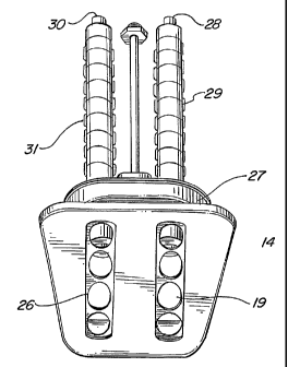
(54) French Title: STRUCTURE A JETS MOBILES ET A BUSES MULTIPLES POUR UN JACUZZI
Status: Granted
Bibliographic Data
(51) International Patent Classification (IPC):
  • A61H 33/04 (2006.01)
(72) Inventors :
  • LARSEN, CHRISTOPHER (United States of America)
(73) Owners :
  • WATKINS MANUFACTURING CORPORATION (United States of America)
(71) Applicants :
  • WATKINS MANUFACTURING CORPORATION (United States of America)
(74) Agent: GOWLING WLG (CANADA) LLP
(74) Associate agent:
(45) Issued: 2009-06-23
(86) PCT Filing Date: 2005-05-05
(87) Open to Public Inspection: 2006-03-02
Examination requested: 2007-04-17
Availability of licence: N/A
(25) Language of filing: English

Patent Cooperation Treaty (PCT): Yes
(86) PCT Filing Number: PCT/US2005/015657
(87) International Publication Number: WO2006/022919
(85) National Entry: 2007-01-15

(30) Application Priority Data:
Application No. Country/Territory Date
10/899,547 United States of America 2004-07-27

Abstracts

English Abstract


A multiple nozzle moving jet structure for a spa, attached to flexible tubes
encased in an articulated sleeve exhausts pressurized water into the spa in a
vertical whipping motion, in reaction to the water exhaust. The multiple
nozzle structure utilizes one air supply tube to aerate water streams of the
multiple nozzle structure. The combination of the multiple nozzle structure
with the articulated sleeves on the flexible tubes, confines movement of the
nozzle structure in one plane, eliminating the requirement for a guide body to
confine direction of nozzle movement.


French Abstract

Structure à jets mobiles et à buses multiples pour un jacuzzi, raccordée à des tubes souples logés dans un manchon articulé, qui éjecte de l'eau sous pression dans le jacuzzi selon un mouvement de fouettement vertical, en réaction à la projection d'eau. Ladite structure à buses multiples comporte un tube d'alimentation en air destiné à aérer les jets d'eau de la structure à buses multiples. La combinaison de la structure à buses multiples et des manchons articulés sur les tubes restreint le mouvement de la structure à buses dans un plan, éliminant ainsi le besoin d'un corps de guidage pour restreindre la direction du mouvement des buses.

Claims

Note: Claims are shown in the official language in which they were submitted.


CLAIMS

1. A moving jet structure for a spa having a tank with sides containing
water for body immersion and a source of pressurized water, the improvement
comprising:
a plurality of flexible tubes connected to the source of pressurized water
at a first end, each tube having a second end which will whip about in
reaction
to the pressurized water exhausting from the second end;

a plurality of articulated sleeves, an articulated sleeve encircling each
one of the plurality of flexible tubes from the first end to the second end,
each
sleeve limiting the flexing of the tube to an arc with a change of direction
at the
end of the arc;

a manifold connecting together the plurality of articulated sleeves at the
second end of the plurality of flexible tubes, the manifold, in combination
with
the plurality of articulated sleeves, constraining movement of the plurality
of
flexible tubes in unison to a vertical plane;
a plurality of nozzles, one nozzle for each one of the flexible tubes,
connected to a flexible tube at the second end, each nozzle moving in unison
with all the other nozzles in a vertical plane, the nozzles exhausting water
into
the tank from a side of the tank.

2. The moving jet structure of claim 1 further comprising:

an air supply for supplying air to the plurality of nozzles.

3. The moving jet structure of claim 1 wherein the manifold is connected
to supply air to each of the plurality of nozzles.

4. The moving jet structure of claim 3 further comprising an air supply
tube connected to the manifold and atmospheric air.

8


5. A moving jet structure for a spa having a tank with sides containing
water for body immersion and a source of pressurized water, the improvement
comprising:
two flexible tubes connected to the source of pressurized water at a first
end, each tube having a second end which will whip about in reaction to the
pressurized water exhausting from the second end;

two articulated sleeves, an articulated sleeve encircling each one of the
two flexible tubes from the first end to the second end, each sleeve limiting
the
flexing of the tube to an arc with a change of direction at the end of the
arc;
a manifold connecting together with two articulated sleeves at the
second end of the flexible tubes, the manifold, in combination with the
articulated sleeves, constraining movement of the flexible tubes in unison to
a
vertical plane;

two nozzles, a nozzle connected to the second end of a flexible tube, the
nozzles moving in unison in a vertical plane, exhausting water into the tank
from a side of the tank.

6. The moving jet structure of claim 5 further comprising an air supply for
supplying air to the two nozzles.

7. The moving jet structure of claim 5 wherein the manifold is connected
to supply air to each of the two nozzles.

8. The moving jet structure of claim 7 further comprising an air supply
tube connected to the manifold and atmospheric air.

9

Description

Note: Descriptions are shown in the official language in which they were submitted.


CA 02574026 2007-01-15
WO 2006/022919 PCT/US2005/015657

MULTIPLE NOZZLE MOVING JET STRUCTURE FOR SPA
BACKGROUND OF THE INVENTION

1. Field of the Invention.
[0001]

The present invention relates generally to improvements in spas or hot
tubs, and more particularly, pertains to new and improved nozzles for ejecting
water into spas wherein, the nozzles physically moved.

2. Description of Related Art.
[0002]

In the field of providing moving water stream ejection into spa containers,
it has been the practice to employ water tubes pivoting in a vertical plane to
exhaust a massaging water stream on the back of the user sitting in the spa.
One
of the problems confronting such devices has been the problem of keeping the
water tubes confined to movement in the vertical plane. Prior art devices such
as, described in U.S. Patents 4,523,340 granted June 18, 1985 for a Means
Providing Moving Water Stream Ejecting Into Spa Tank, U.S. Patent 4,716,604
granted January 5, 1988 for a Spa With Moving Jets, and U.S. Patent 4,920,588
granted May 1, 1990 for a Means Providing Moving Water Stream Ejecting Into
Spa Tank, utilized as specially designed guide body to guide the moving
nozzles
to move only in the vertical plane.

1


CA 02574026 2007-01-15
WO 2006/022919 PCT/US2005/015657
Figure 1 is an illustration of a prior art , single nozzle moving jet
structure. This type of structure is described in detail in U.S. Patents
4,523,340,4,716,604, and 4,920,588. These structures all have a single nozzle
21, connected to a source of air supply by tubing 25, and a source of
pressurized
water by tubing 23. The pressurized water is supplied to the nozzle 21 in a
flexible tube encased in an articulated plastic sleeve structure. This
articulated
sleeve structure is more specifically described in U.S. Patent No. 4,716,604,
which is assigned to the assignee of the present invention. The nozzle 21
moves
up and down vertically, as the result of a whipping reaction to the exhaust
water
from the nozzle. The nozzle 21 is confined to the vertical path of travel by
the
combination of the articulated plastic sleeve over tubing 23, and the guide
body
17, which is a series of fins or ribs, as described in detail in U.S. Patent
No. 4,716,604. The water from the nozzle 21 is ejected through an opening or
series of ports 19 on a face plate 13. Face plate 13 mounts to a flange 15
which
is attached to the tank wall of the spa, in a manner described in detail in
U.S.
Patents 4,523,340, 4,716,604 and 4,920,588.

[0003]
In contrast, the present invention increases the amount of massaging
water streams on the back of a user, while at the same time eliminating the
requirement for using guide bodies and reducing the amount of air supply
tubing line required.

2


CA 02574026 2007-01-15
WO 2006/022919 PCT/US2005/015657

SUMMARY OF THE INVENTION
[0004]

A multiple nozzle structure mounted to respective pressurized water
tubes which are individually encased in articulated sleeves with one air
supply
tube supplying air to all the nozzles, confines the nozzle structure movement
resulting from the, water exhaust, to one plane. No guide body is required to
confine the direction of movement of the nozzle structure. Movement of the
nozzle structure is preferred in the vertical plane to obtain movement up and
down the back of a person in the spa.

BRIEF DESCRIPTION OF THE DRAWINGS
[0005]

The exact nature of this invention, as well as its objects and many of the
attended advantages, will become readily apparent upon reference to the
following detailed description considered in conjunction with the accompanying
drawings in which like reference numerals designate like parts throughout the
figures thereof and wherein:

[0006]
Figure 1 is a back perspective of a prior art, single nozzle moving jet
structure.

3


CA 02574026 2007-01-15
WO 2006/022919 PCT/US2005/015657
[0007]

Figure 2 is a top perspective of a multiple nozzle moving jet structure,
according to the present invention.

[0008]
Figure 3 is a side perspective of the multiple nozzle moving jet structure
of Figure 2.

[0009]
Figure 4 is back perspective of the multiple nozzle moving jet structure of
Figure 2.

[0010]
Figure 5 is a cross section of a preferred embodiment of the multiple
nozzle used in the multiple nozzle moving jet structure of the present
invention.

4


CA 02574026 2009-01-13

DETAILED DESCRIPTION OF THE PREFERRED EMBODIMENTS OF THE
INVENTION
[0011]

Figures 2, 3 and 4 illustrate a preferred embodiment of the present invention
as
having a two nozzle moving jet structure. Each nozzle 35, 37 is supplied with
pressurized water over respective flexible tubing 30 and 28. A single air line
33
supplies air to an air manifold 39, which physically attaches to both nozzles
35 and 37
in a manner that makes the two nozzle 35 and 37 a single unit.

[0012]
Each of the flexible water supply tubes 30 and 28 are encased in respective
articulated plastic sleeves 31 and 29, of the type described in U.S. Patent
4,716,604
granted June 5, 1988 for a Spa With Moving Jets.

[0013]
The multiple articulated sleeves 29 and 31 in conjunction with the multiple
jet
37, 35 moving structure, constrains movement of the multiple jet head 35, 37
to a
single chosen plane, which in the figures is illustrated to be a vertical
plane. Head 35,
37 moves in an up-down direction, back and forth, from a top location 35 to a
bottom
location 35', as shown in figure 3. It should be kept in mind, however, that
the chosen


CA 02574026 2009-01-13

plane could be other than vertical. The chosen plane could be horizontal, for
example,
or a plane at an angle to the horizontal, as desired.

[0014]
A mounting flange 27, which is attached to the tank wall of the spa, acts as a
support for the face plate 14, which has a first plurality of apertures 19 and
a parallel
second plurality of apertures 26 aligned vertically, to allow water being
ejected from
the nozzles 35 and 37 to be injected into the body of water in the spa (not
shown).

[0015]
The multiple nozzle moving jet structure of the present invention not only
eliminate the need for a guide body structure, for guiding nozzle movement,
but it also
provides a more significant quantity of massaging jets which is a quantum
improvement to the experience of the occupant in the spa tank.

[0016]
An air manifold 39, which receives air from a flexible air supply tube 33,
physically connects the jets 35 and 37 together, as well as supplying air to
each of the
jets, in a manner more clearly illustrated in Figure 5.

[0017]
Figure 5, which is a cross section of a two nozzle moving jet structure shows
the air manifold 39 receiving air by way of a flexible air supply line 33,

6


CA 02574026 2009-01-13

from an air line 34 that is connected to a valve 36, which opens to the
atmosphere. Air
manifold 39 is connected to nozzle 35 by passage 41, and is connected to
nozzle 37 by
passage 43. Pressurized water is supplied to nozzle 35 by flexible tubing 30
that
attaches to an input nipple 34. Flexible tubing 30 is connected to a pump 32,
that
pumps water from the spa tank. Nozzle 37 receives pressurized water over
flexible
tubing 28 from the pump 32. Tubing 28 attaches to the input nipple 32 of
nozzle 37.

[0018] The structure of nozzles 35 and 37 are identical in that, each has
an exhaust tube 51 and 49 with a space at the bottom for drawing air, through
the gap
from respective air chambers 47 and 45. The specific operation of nozzles such
as
nozzles 35 and 37 is explained in detail in U.S. Patent 4,920,588.

[0019] It should be remembered that more than two nozzles could be
utilized in a multiple nozzle moving jet structure, according to the present
invention,
and using more than two nozzles is contemplated within the present invention.
The
arrangement of three or more nozzles in combination with the air manifold,
using the
nozzle structure illustrated, or an alternate nozzle structure, is considered
part of the
present invention.

7

Representative Drawing
A single figure which represents the drawing illustrating the invention.
Administrative Status

For a clearer understanding of the status of the application/patent presented on this page, the site Disclaimer , as well as the definitions for Patent , Administrative Status , Maintenance Fee  and Payment History  should be consulted.

Administrative Status

Title Date
Forecasted Issue Date 2009-06-23
(86) PCT Filing Date 2005-05-05
(87) PCT Publication Date 2006-03-02
(85) National Entry 2007-01-15
Examination Requested 2007-04-17
(45) Issued 2009-06-23

Abandonment History

There is no abandonment history.

Payment History

Fee Type Anniversary Year Due Date Amount Paid Paid Date
Application Fee $400.00 2007-01-15
Maintenance Fee - Application - New Act 2 2007-05-07 $100.00 2007-04-16
Request for Examination $800.00 2007-04-17
Registration of a document - section 124 $100.00 2007-04-27
Maintenance Fee - Application - New Act 3 2008-05-05 $100.00 2008-04-07
Maintenance Fee - Application - New Act 4 2009-05-05 $100.00 2009-03-30
Final Fee $300.00 2009-04-07
Maintenance Fee - Patent - New Act 5 2010-05-05 $200.00 2010-04-07
Maintenance Fee - Patent - New Act 6 2011-05-05 $200.00 2011-04-18
Maintenance Fee - Patent - New Act 7 2012-05-07 $200.00 2012-04-16
Maintenance Fee - Patent - New Act 8 2013-05-06 $200.00 2013-04-15
Maintenance Fee - Patent - New Act 9 2014-05-05 $200.00 2014-04-15
Maintenance Fee - Patent - New Act 10 2015-05-05 $250.00 2015-04-13
Maintenance Fee - Patent - New Act 11 2016-05-05 $250.00 2016-04-12
Maintenance Fee - Patent - New Act 12 2017-05-05 $250.00 2017-04-13
Maintenance Fee - Patent - New Act 13 2018-05-07 $250.00 2018-04-12
Maintenance Fee - Patent - New Act 14 2019-05-06 $250.00 2019-04-15
Maintenance Fee - Patent - New Act 15 2020-05-05 $450.00 2020-04-21
Maintenance Fee - Patent - New Act 16 2021-05-05 $459.00 2021-04-13
Maintenance Fee - Patent - New Act 17 2022-05-05 $458.08 2022-04-12
Maintenance Fee - Patent - New Act 18 2023-05-05 $473.65 2023-04-21
Maintenance Fee - Patent - New Act 19 2024-05-06 $473.65 2023-11-10
Owners on Record

Note: Records showing the ownership history in alphabetical order.

Current Owners on Record
WATKINS MANUFACTURING CORPORATION
Past Owners on Record
LARSEN, CHRISTOPHER
Past Owners that do not appear in the "Owners on Record" listing will appear in other documentation within the application.
Documents

To view selected files, please enter reCAPTCHA code :


To view images, click a link in the Document Description column. To download the documents, select one or more checkboxes in the first column and then click the "Download Selected in PDF format (Zip Archive)" or the "Download Selected as Single PDF" button.

List of published and non-published patent-specific documents on the CPD .

If you have any difficulty accessing content, you can call the Client Service Centre at 1-866-997-1936 or send them an e-mail at CIPO Client Service Centre.


Document
Description 
Date
(yyyy-mm-dd) 
Number of pages   Size of Image (KB) 
Abstract 2007-01-15 2 83
Claims 2007-01-15 3 83
Drawings 2007-01-15 3 88
Description 2007-01-15 7 223
Representative Drawing 2007-03-20 1 11
Cover Page 2007-03-21 1 41
Description 2009-01-13 7 210
Claims 2009-01-13 2 72
Drawings 2009-01-13 3 89
Representative Drawing 2009-06-01 1 12
Cover Page 2009-06-01 2 46
PCT 2007-01-15 1 18
Assignment 2007-01-15 3 81
Correspondence 2007-03-12 1 27
PCT 2007-01-16 4 163
Assignment 2007-04-27 4 154
Prosecution-Amendment 2007-04-17 2 46
Fees 2007-04-16 1 42
Prosecution-Amendment 2007-06-11 2 40
PCT 2007-01-16 7 241
Prosecution-Amendment 2008-11-04 2 50
Prosecution-Amendment 2009-01-13 10 386
Correspondence 2009-04-07 2 52