Note: Descriptions are shown in the official language in which they were submitted.
CA 02574099 2007-O1-30
-1-
THERMAL REACTOR FOR INTERNAL COMBUSTION ENGINE
FUEL MANAGEMENT SYSTEM
BACKGROUND OF THE INVENTION
This is a divisional application of Canadian Patent Application Serial No.
2,306,861 filed on October 20, 1998.
1. FIELD OF THE INVENTION
The invention relates to internal combustion engines, and more particularly,
to a
fuel management system for an internal combustion engine fueled by a liquid
hydrocarbon. It should be understood that the expression "the invention" and
the like
encompasses the subject matter of both the parent and the divisional
applications.
2. DESCRIPTION OF RELATED ART
The operation of internal combustion engines is well known. In an internal
combustion engine, combustion of fuel takes place in a confined space,
producing expanding
gases that are used to provide mechanical power. The most common internal-
combustion
engine is the four-stroke reciprocating engine used in automobiles. Here,
mechanical power
is supplied by a piston fitting inside a cylinder. On a downstroke of the
piston, the first
stroke, fuel that has been mixed with air (by fuel injection or using a
carburetor) enters the
cylinder through an intake valve via an intake manifold. The intake manifold
is a system of
passages that conduct the fuel mixture to the intake valves. The piston moves
up to compress
the mixture at the second stroke. At ignition, the third stroke, a spark from
a spark plug
ignites the mixture, forcing the piston down. In the exhaust stroke, an
exhaust valve opens to
vent the burned gas as the piston moves up. A rod connects the piston to a
crankshaft. The
reciprocating (up and down) movements of the piston rotate the crankshaft,
which is
connected by gearing to the drive wheels of the automobile.
A diesel engine is another type of internal-combustion engine. It is generally
heavier
and more powerful than the gasoline engine and burns diesel fuel instead of
gasoline. It
differs from the gasoline engine in that, among other things, the ignition of
fuel is caused by
compression of air in its cylinders instead of by a spark. The speed and
powder of the diesel
are controlled by varying the amount of fuel injected into the cylinder.
In this disclosure, a fuel is defined as a substance that can be burned by
supplying air
and a sufficient amount of heat to initiate combustion. A liquid hydrocarbon
fuel, such as
CA 02574099 2007-O1-30
-2-
gasoline or diesel fuel, must be converted to a gas before it can be ignited.
This liquid to gas
vapor conversion is required because the molecules of fuel must be well mixed
with the
molecules of air before they can chemically react with each other to give
of~heat.
However, not all of the liquid fuel must be converted to a gas before
combustion can
s occur. Just enough fuel needs to be converted to a gas so that the mixture
of gas molecules
and air molecules falls within the fuel's flammability limits -- which refers
to the minimum
and maximum concentration percentages, by weight, of fuel in air that will
bum. If the
concentration of the gaseous fuel'in air is less than the minimum or greater
than the
maximum flammability limit, the fuel and air mixture will not ignite. Known
internal
~o combustion engines and fuel delivery systems are inefficient in converting
the liquid fuel to a
gaseous state. Therefore, the fuel and air molecules cannot mix properly for
complete
combustion.
In a gasoline engine employing a standard automotive throttle body fuel
injection
system, this inefficiency is due at least in part to the high velocity of the
air and fuel mixture
is passing the fuel injection's throttle body, which may reduce the inlet
temperature as low as
40°F (4°C). The flash point temperature -- the temperature at
which the fuel will give off
enough vapor to form a combustible mixture with air -- for gasoline is
45°F (7°C). This
reduction in inlet temperature reduces the amount of heat available from the
atmosphere to
evaporate the fuel. Since less ambient heat is available, more energy from
compressing the
Zo mixture is required to evaporate the fuel.
Gasoline engines have a throttle valve to control the volume of intake air.
The
amount of fuel and air that goes into the combustion chamber regulates the
engine speed and,
therefore, engine power. This causes continuous changes in the atmospheric air
velocity due
to the pressure differential between the atmosphere and the intake manifold.
These pressure
zs variations cause the size of the particles of atomized fuel to vary
throughout the engine's
RPM range. As a result, there is a wide variation in fuel droplet size in the
air stream.
Therefore, the fuel droplets have less surface area exposed to the air for
evaporation arid more
heat is required to fully evaporate the fuel.
CA 02574099 2007-O1-30
-3-
Once the fuel vapor and air mixture leaves the throttle body injector and
enters the
intake manifold, the mixture velocity is so high thaf some of the fuel
droplets are centrifuged
out of the air stream when they make toms. This occurs because the fuel
droplets are heavier
than air. This varies that portion of the mixture's stoichiometric fuel to air
ratio, even though
s the overall air to fuel ratio of the mixture flowing through the fuel
injector is correct. The
portion of the mixture that contains the fuel that was centrifuged out of the
main air stream
reduces the amount of surface area exposed by the fuel to the air for
evaporation. This
increases the amount of energy required to evaporate it. Once this portion of
the fuel mixture
is evaporated, it burns rich since the original portion of this mixture was
rich from the fuel
~o being centrifuged out of the main air stream. Carbony residues that
accumulate in the
combustion chambers and darker areas on the piston tops indicate areas of
excessive fuel
richness during combustion.
Conversely, portions of the air stream that are lean, but still fall within
the
flammability limits, will bum and cause extremely high temperatures. Auto-
ignition
~s temperature refers to the temperature at which a mixture of air and fuel
will spontaneously
ignite without open flame, spark, or a hot spot. The auto-ignition temperature
of gasoline is
495°F (275°C). When these localized high temperature areas reach
high enough pressure and
temperature, autoignition of the end gases will result, causing detonation,
which is the
uncontrolled combustion or explosion caused by auto-ignition of the end gases
that were not
Zo consumed in the normal flame front reaction. Detonation results in the
familiar "ping" or
"spark knock" sound.
The engine's heat of compression during the compression stroke produces heat
that
begins to evaporate the air and fuel mixture in the cylinder. However, this
compressing of the
mixture increases the pressure. As a result, the increased pressure increases
the boiling point
zs of the fuel for evaporation. Evaporation continues slowly because these
relationships are, not
linear. So enough fuel evaporates, allowing it to fall within its flammability
limits. Then the
spark plug ignites the mixture and creates a flame front. This flame front
during the
combustion process has the same effect of increasing the boiling point of the
fuel so its
critical temperature is never reached. Therefore, the remaining atomized fuel
droplets do not
CA 02574099 2007-O1-30
-4-
evaporate before or during combustion. Since the droplets are not vaporized,
they do not
burn.
When the cylinder pressure falls due to the descent of the piston while on the
power
stroke, the fuel droplets that were not evaporated earlier now evaporate due
to a lower boiling
s point and higher cylinder temperature. These evaporated fuel droplets now
bum, but they
bum too late into the crankshaft angle for producing power. Thus, less power
and high
exhaust gas temperatures result.
Direct (intake) port fuel injection has better fuel distribution
characteristics than a
throttle body fuel injection system. However, they allow very little time to
evaporate fuel in
io the intake port. Therefore, the heat of compression must heat the air/fuel
mixture for
evaporation before combustion can occur. This system has the same inherent
inefficiencies
regarding the engine's heat of compression, which increases the boiling point
of the fuel.
Therefore, as the cylinder pressure rises, the critical temperature is never
reached. The.
remaining fuel droplets do not bum in time to produce power. Thus, less power
and high
~s exhaust gas temperatures still result.
The heat of combustion (the temperature in the cylinder due to combustion) for
gasoline is 840°F (449°C) plus or minus 40°F (4°C)
above ambient. Conventional
automotive exhaust gas temperatures are 1,400 to 1,500°F (760 to
815°C). This temperature
difference (heat energy) between the exhaust gas temperature and the heat of
combustion is
Zo totally wasted as excessive exhaust gas temperature. Even the engine's
cooling system must
be enlarged to dissipate the higher exhaust gas temperatures due to the
increased temperature
differential around the exhaust side of the combustion chambers and exhaust
ports. This
wasted heat energy is dissipated to the atmosphere through the vehicle's
radiator, and an
equal amount of wasted heat energy is dissipated through the vehicle's exhaust
pipes as
zs excessively high exhaust gas temperatures.
The remaining fuel that did not chemically react in the combustion chamber or
in the
exhaust manifold then enters a 2,000°F (1,093°C) catalytic
converter for combustion. The
unburned fuel that escapes the catalytic converter enters the atmosphere as
hydrocarbon and
carbon-monoxide pollutants. Moreover, currently produced catalytic converters
are only
CA 02574099 2007-O1-30
-5-
effective when the engine is at operating temperature, so it has no effect on
cold start
emission levels.
Similar shortcomings exist with known diesel engines. In diesel engines with
indirect
fuel injection (precombustion chamber), the engine's heat of compression
during the
s compression stroke produces heat that begins to evaporate the air and fuel
mixture in the
cylinder. However, this compressing of the mixture increases the pressure. As
a result, the
increased pressure increases the boiling point of the fuel for evaporation.
Evaporation
continues slowly because these relationships are not linear, and just enough
of the aromatics
in the diesel fuel evaporate allowing it to fall within its flammability
limits. The flash point
~o temperature of the aromatics is low enough for the air and fuel mixture to
auto-ignite, which
results in a flame front. This flame front ignites more of the fuel mixture
during the
combustion process; however, it has the same effect of increasing the boiling
point of the fuel
so its critical temperature is never reached. Therefore, the remaining liquid
fuel droplets do
not evaporate before or during combustion.
~s Diesel engines with direct-injection (DI) have even greater fuel
vaporization
problems. In a diesel engine with DI high turbulence combustion chambers, the
fuel spray
pattern elongates in response to air flow. The smaller fuel droplets
concentrate on the leading
(lower) edge of the spray pattern while the larger and heavier droplets remain
clustered about
the core.
2o Ignition begins as a series of small bursts at the interface between the
fuel spray and
cylinder air, where there is surplus of oxygen. The bursts combine into flame
fronts that
progressively move into the fuel-soaked core of the pattern. Every normal
combustion event
in a diesel engine begins under oxygen-rich conditions and concludes under
oxygen-lean
conditions. This variability in fuel/air ratios is a special burden of the
diesel engine. In
zs addition, diesel engines operate under a fairly wide range of loads and
speeds. Air
turbulence, duration of the expansion stroke (power), and cylinder temperature
vary with the
operating mode.
Hydrocarbons survive their passage through the cylinder when the mixture is
either
too lean or too rich to burn. Excessively lean mixtures are caused by fuel
droplets that break
CA 02574099 2007-O1-30
-6-
free of spray plume and diffuse throughout the combustion chamber. The
resulting fuel
mixture does not support combustion, and the raw fuel exists through the
exhaust. This
phenomenon often occurs under light loads and at low engine speeds, which
causes high
hydrocarbon emission spikes during idle. Hydrocarbon emissions are also
generated when
s the flame is quenched by too rapid infusion of air or by contact with the
relatively cool
cylinder walls.
Particulate Matter (PM) in high concentrations that accompany diesel
acceleration and
cold starts can be seen as black smoke. The hydrocarbon component of PM,
referred to as
soluble organic fraction (SOF), consists of combustion by-products, Tube oil
and unburned
~o fuel. Soot, the SOF carrier, forms in the oxygen-poor (rich fuel mixture)
region on the
trailing edge of the fuel plume. Oxides of nitrogen (NOx) are created in the
high-
temperature, oxygen-rich combustion (fuel-lean mixture) that occurs on the
leading edge of
the spray plume. Most soot forms early in the combustion process when fuel
accumulates
during the ignition lag period, then burns at extremely high temperatures to
form NOx.
is When the cylinder pressure falls due to the descent ofthe piston while on
the power
stroke, the fuel droplets that were not evaporated earlier now evaporate due
to a lower boiling
point and higher cylinder temperature. These evaporated fuel droplets now
burn, but they
burn too late into the crankshaft angle for producing power. Thus, less power,
high emission
levels, and high exhaust gas temperatures result.
2o The heat of combustion for diesel fuel is 500 to 550°F (260 to
288°C) above ambient.
Convention diesel exhaust gas temperatures are 1,100 to 1,300°F (593 to
704°C). As with a
gasoline engine, this temperature difference (heat energy) between the diesel
exhaust gas
temperature and the heat of combustion is totally wasted as excessive exhaust
gas
temperature. Thus, the engine's cooling system must be enlarged to dissipate
the higher
Zs exhaust gas temperatures due to the increased temperature differential
around the exhaust side
of the combustion chambers and exhaust ports. This wasted heat energy is
dissipated to the
atmosphere through the vehicle's radiator, and an equal amount of wasted heat
energy is
dissipated through the vehicle's exhaust pipes as excessively high exhaust gas
temperatures.
CA 02574099 2007-O1-30
_7_
The present invention addresses some of the above mentioned, and other,
shortcomings associated with the prior art.
SUMMARY OF THE INVENTION
In one aspect of the present invention, a fuel management system for an
internal
s combustion engine is presented. The internal combustion engine includes,
among other
things, an intake manifold, and the fuel management system includes a thermal
reactor having
an inlet port and an outlet port. The thernial reactor receives liquid fuel
through the inlet port,
and is adapted to heat the liquid fuel and discharge fuel vapor through the
outlet port. A
pressure sensing device is configured to measure pressure within the intake
manifold to
~o determine engine load, and a plenum is adapted to receive the fuel vapor
from the outlet port
and mix the fuel vapor with air. The plenum is adapted to be connected to the
intake
manifold to provide the fuel vapor and air mixture to the intake manifold. A
fuel metering
device is operable to regulate the amount of fuel vapor provided to the plenum
in response to
the pressure sensing device.
is In another aspect of the invention, a thermal reactor for converting a
liquid
hydrocarbon fuel to a fuel vapor includes a cylinder defining an axial bore
therethrough. The
cylinder further defines an inlet port adapted to receive the liquid
hydrocarbon fuel, and an
outlet port adapted to discharge the fuel vapor. At least one heating element
is connected to
the cylinder and is arranged to heat the liquid hydrocarbon fuel to convert
the liquid fuel to
2o the fuel vapor.
In yet another aspect of the present invention, a system for preventing
cylinder over
scavenging during the overlap period of a camshaft in an internal combustion
engine is
provided. The engine includes an exhaust manifold and an exhaust pipe coupled
thereto. The
system includes a pressure sensor to measure back pressure of exhaust gas from
the engine
zs and a control valve coupled to the exhaust pipe. The control valve is
responsive to the
pressure sensor to restrict the exhaust gases and apply back pressure on the
engine.
In a still further aspect, a method of dynamically mapping operating
parameters of an
engine is provided. The method includes configuring a plurality of measurement
devices to
indicate a plurality of engine parameters, operating the engine, recording the
outputs of the
CA 02574099 2007-O1-30
_g_
measurement devices while the engine is operating, and playing back the
recorded
outputs at predetermined time intervals. In a particular embodiment, the
recording of the
outputs comprises video taping the outputs of the measurement devices.
According to an aspect of the present invention there is provided a fuel
management system for an internal combustion engine including an intake
manifold, the
fuel management system comprising a thermal reactor having an inlet port and
an outlet
port, the thermal reactor receiving liquid fuel through the inlet port, the
thermal reactor
heating the liquid fuel to convert the liquid fuel to a fuel vapor and
discharge the fuel
vapor through the outlet port, a pressure sensing device for measuring
pressure within the
intake manifold to determine engine load, a plenum connected to the outlet
port to
receive the fuel vapor from the outlet port and mix the fuel vapor with air, a
fuel metering
device connected to the pressure sensing device for regulating the fuel vapor
provided to
the plenum in response to the pressure sensing device, and an air intake
velocity valve
connected to the plenum, the air intake velocity valve controlling the air
provided to the
plenum in response to the pressure sensing device.
According another aspect of the invention there is provided a fuel management
system for an internal combustion engine fueled by a liquid hydrocarbon, the
engine
including an intake manifold and a turbocharger, the fuel management system
comprising
a thermal reactor having an inlet port and an outlet port, the thermal reactor
receiving the
liquid hydrocarbon fuel through the inlet port, the thermal reactor heating
the liquid
hydrocarbon fuel to convert the liquid hydrocarbon fuel to a fuel vapor and
discharge the
fuel vapor through the outlet port, a pressure sensing device for measuring
pressure
within the intake manifold to determine engine load, and a fuel metering
device
connected to the outlet port of the thermal reactor such that the fuel vapor
is discharged
from the thermal reactor and through the fuel metering device, the fuel
metering device
regulating the fuel vapor discharged from the thermal reactor in response to
the pressure
sensing device.
According to a fiu~ther aspect of the present invention there is provided a
fuel
management system for an internal combustion engine including an intake
manifold, the
fuel management system comprising a thermal reactor having an inlet port and
an outlet
port, the thermal reactor receiving liquid fuel through the inlet port, the
thermal reactor
heating the liquid fuel to convert the liquid fuel to fuel vapor and discharge
the fuel vapor
through the outlet port, a pressure sensing device for measuring pressure
within the
CA 02574099 2007-O1-30
-8a-
intake manifold to determine engine load, a plenum coupled to the outlet port
to receive
the fuel vapor from the outlet port and mix the fuel vapor with air, a fuel
metering device
switched between first and second stages in response to the pressure sensing
device, the
first stage providing fuel vapor from the thermal reactor to the plenum at a
first rate to
achieve a first predetermined air to fuel vapor ratio, the second stage
providing fuel vapor
from the thermal reactor to the plenum at a second rate to achieve a second
predetermined air to fuel vapor ratio, and a controller switching the fuel
metering device
between the first and second stages in response to a predetermined engine
parameter.
According to a further aspect of the present invention there is provided a
fuel
management system for an internal combustion engine including an intake
manifold, the
fuel management system comprising a thermal reactor having an inlet port and
an outlet
port and a cylinder defining an axial bore therein, the cylinder defining a
side wall having
a plurality of apertures extending therethrough, the cylinder receiving liquid
fuel from the
inlet port, a plurality of heating elements, each aperture having one of the
heating
elements extending therethrough such that the liquid fuel received into the
cylinder
contacts the heating elements to heat the liquid fuel so as to convert the
liquid fuel to a
fuel vapor and discharge the fuel vapor through the outlet port, a pressure
sensing device
connected to the thermal reactor for measuring pressure within the intake
manifold to
determine engine load, and a plenum connected to the thermal reactor outlet
port to
receive the fuel vapor from the outlet port and mix the fuel vapor with air.
According to a further aspect of the present invention there is provided a
fuel
management system for an internal combustion engine including an intake
manifold, the
fuel management system comprising a thermal reactor comprising a cylinder
defining an
axial bore therein, the cylinder defining a side wall and an outlet port, at
least one fuel
bar connected to the side wall, the fuel bar defining at least one fuel well
in fluid
communication with the cylinder, the fuel well defining an inlet port for
receiving liquid
fuel into the fuel well, at least one heating element disposed within the fuel
bar, such that
the liquid fuel received into the fuel well contacts the heating element to
heat the liquid
fuel so as to convert the liquid fuel to a fuel vapor and discharge the fuel
vapor through
the outlet port, a pressure sensing device connected to the thermal reactor
for measuring
pressure within the intake manifold to determine engine load, and a plenum
connected to
the thermal reactor outlet port to receive the fuel vapor from the outlet port
and mix the
fuel vapor with air.
CA 02574099 2007-O1-30
-8b-
According to a further aspect of the present invention there is provided a
fuel
management system for an internal combustion engine fueled by a liquid
hydrocarbon,
the engine including an intake manifold and a turbocharger, the fuel
management system
comprising a thermal reactor having an inlet port and an outlet port, the
thermal reactor
receiving the liquid hydrocarbon fuel through the inlet port, a plurality of
heating
elements disposed in the thermal reactor for heating the liquid hydrocarbon
fuel to
convert the liquid hydrocarbon fuel to a fuel vapor, the fuel vapor being
discharged
through the outlet port, a pressure sensing device connected to the thermal
reactor for
measuring pressure within the intake manifold to determine engine load, a fuel
metering
device connected to the outlet port of the thermal reactor to regulate the
fuel vapor
discharged from the thermal reactor in response to the pressure sensing
device, and an air
intake velocity valve connected to the fuel metering device, the air intake
velocity valve
controlling the air mixed with the fuel vapor in response to the pressure
sensing device.
BRIEF DESCRIPTION OF THE DRAWINGS
Other objects and advantages of the invention will become apparent upon
reading the
following detailed description and upon reference to the drawings in which:
Figure 1 is a block diagram illustrating a fuel management system in
accordance with
an embodiment of the present invention;
Figure 2 is a block diagram illustrating a fuel management system in
accordance with
an alternative embodiment of the present invention;
Figure 3 is a block diagram illustrating a fuel management system in
accordance with
another alternative embodiment of the present invention;
Figure 4 is a side view of an embodiment of a thermal reactor in accordance
with the
present invention;
Figure 5 is a front perspective view of a cylinder suitable for a thermal
reactor such as
the embodiment illustrated in Figure 4;
Figwe 6 is a perspective view of a first end plate for a thermal reactor such
as the
embodiment illustrated in Figure 4;
Figure 7 is a perspective view of a second end plate for a thermal reactor
such as the
embodiment illustrated in Figure 4;
Figwe 8 is a perspective view of a cylinder adapted for an alternative
embodiment of
a thermal reactor in accordance with the present invention;
CA 02574099 2007-O1-30
$C
Figure 9 is a front perspective view of a fuel metering device in accordance
with an
embodiment of the present invention;
Figure 10 is a top perspective view of the fuel metering device shown in
Figure 9;
Figure 1 I is a side perspective view of the- fuel metering device shown in
Figure 9;
Figure 12 is a block diagram illustrating a fuel management system in
accordance
with yet another alternative embodiment of the present invention;
CA 02574099 2007-O1-30
-9-
Figure 13 is a perspective view of a plenum in accordance with an embodiment
of the
presentinvention;
Figure l4 is a block diagram illustrating an exhaust control system in
accordance with
an embodiment of the present invention;
Figure 15 is a perspective view of an exhaust system thermal reactor in
accordance
with the present invention; and
Figure 16 illustrates a glow plug system in accordance with an embodiment of
the
presentinvention;
Figure 17 is a flow diagram illustrating a mapping process in accordance with
an
~o embodiment of the present invention.
While the invention is susceptible to various modifications and alternative
forms,
specific embodiments thereof have been shown by way of example in the drawings
and are
herein described in detail. It should be understood, however, that the
description herein of
specific embodiments is not intended to limit the invention to the particular
forms disclosed,
is but on the contrary, the intention is to cover all modifications,
equivalents, and alternatives
falling within the spirit and scope of the invention as defined by the
appended claims.
DETAILED DESCRIPTION OF THE INVENTION
111ustrative embodiments of the invention are described below. In the interest
of
clarity, not all features of an actual implementation are described in this
specification. It will
zo of course be appreciated that in the development of any such actual
embodiment, numerous
implementation-specific decisions must be made to achieve the developers'
specific goals,
such as compliance with system-related and business-related constraints, which
will vary
from one implementation to another. Moreover, it will be appreciated that such
a
development effort might be complex and time-consuming, but would nevertheless
be a
zs routine undertaking for those of ordinary skill in the art having the
benefit of this disclosure.
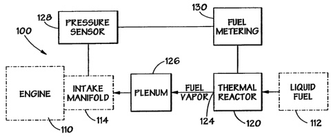
Figure I is a block diagram illustrating a fuel management system 100 in
accordance
with one embodiment of the present invention. Specific embodiments of the
present
invention are configured for use as an add-on system for an original equipment
manufacture's
(OEM) engine. The fuel management system 100 is adapted for use with an
internal
CA 02574099 2007-O1-30
-lU-
combustion engine 110 using a liquid hydrocarbon fuel 112, such as gasoline,
diesel fuel,
kerosene, alcohols, etc., which is typically contained in a fuel tank. Among
other things, the
engine 112 includes an intake manifold 114 for conducting an air/fuel mixture
to the intake
valves (not shown) of the engine 112.
s The exemplary fuel management system 100 includes a thermal reactor 120
having an
inlet port 122 and an outlet port 124. The thermal reactor 120 receives liquid
fuel 112,
typically from a vehicle's fuel tank, through the inlet port 122. The thermal
reactor 120 heats
the liquid fuel I 12 to convert it to fuel vapor, which is then discharged
through the outlet port
124. A plenum 126 receives the fuel vapor and thoroughly mixes it with air.
The fuel vapor
~o and air mixture then flows from the plenum 126 to the intake manifold 114
to provide the fuel
vapor and air mixture to the intake manifold. A pressure sensing device 128 is
configured to
measure pressure within the intake manifold 114 to determine engine load, and
a fuel
metering device 130 is operable to regulate the amount of fuel vapor provided
to the plenum
126 in response to the pressure sensing device 128, thus providing the leanest
possible air to
is fuel vapor ratio for the engine 112 load condition. In certain embodiments
adapted for use
with a turbocharged engine, such as a turbocharged diesel engine, the engine's
native
turbocharger may provide the function of the plenum 126. Hence, the plenum 126
would not
be necessary in such an implementation, and the fuel vapor from the thermal
reactor 120
would be provided directly to the turbocharger.
zo The fuel metering device 130 may be situated in various positions relative
to the
thermal reactor 120 in accordance with various embodiments of the invention.
In a particular
embodiment, such as the system 101 illustrated in Figure 2, the fuel metering
device 130 is
connected to the outlet port 124 of the thermal reactor 120, such that the
fuel vapor passes
from the thermal reactor 120 outlet port 124, through the fuel metering device
130, to the
is plenum 126. In another alternative embodiment shown in Figure 3, the fuel
metering device
is coupled to the inlet port 122 of the thermal reactor 120, such that the
liquid fuel 112 passes
through the fuel metering device 130 to the thermal reactor inlet 122.
Turning now to Figure 4 and Figure 5, an exemplary thermal reactor 120 in
accordance with a particular embodiment of the invention is illustrated. The
thermal reactor
CA 02574099 2007-O1-30
-11-
120 functions to heat liquid fuel to convert it to a fuel vapor, and further,
it serves as a surge
tank of fuel vapor to meet engine demands while liquid fuel is being
processed. The thermal
reactor 120 comprises a cylinder 140 defining an axial bore 142 therethrough.
The cylinder
140 is adapted to receive the liquid fuel 112 from the inlet port 122 and
discharge the fuel
s vapor through the outlet port 124. In the particular embodiment illustrated
in Figure 4 and
Figure 5, a first end plate 144 that is connected to a first end 145 of the
cylinder 140 defines
the inlet port 122, and a side wall 146 of the cylinder 140 defines the outlet
port 124. At least
one heating element 148 is provided to heat the liquid fuel and thus, to
convert the liquid fuel
to the fuel vapor.
~o The thermal reactor 120 shown in Figure 4 and Figure 5 includes a plurality
of heating
elements 148 disposed in the cylinder 140, with the heating elements 148
arranged such that
the liquid fluid contacts the heating elements 148. The side wall 146 of the
cylinder 140 has
a plurality of apertures I 50 extending therethrough, with each of the
apertures I 50 having one
of the heating elements 148 extending therethrough, so that each heating
element 148 projects
is into the cylinder 140 (only two heating elements 148 are shown extending
through the
apertures 150 in Figure 5 to simplify the illustration). In certain
embodiments, each of the
heating elements 148 is positioned generally perpendicular to the axis of the
cylinder 140,
and each of the apertures 150 has a corresponding aperture 150 located about
90 degrees
therefrom, as illustrated in Figure 5. More specifically, the apertures 1 SO
are arranged in two
2o columns, with each column being generally parallel to the axis of the
cylinder 140 and
positioned about 90 degrees apart.
In one specific embodiment of the thermal reactor 120A, the cylinder 140 is
about
12.125 inches (30.80 cm) long, with a diameter of about 4.0 inches (10.2 cm).
Each of the
columns 151, 152 of apertures 150 includes 12 apertures, for total of 24
apertures 150
Zs extending through the cylinder 140. Each aperture 150 is 0.375 inches (.95
cm) in diameter
and is threaded. The apertures 150 are positioned such that the center of the
first aperture 150
of the first column 151 is 1 _3125 inches (3.33 cm) from the first end 145 of
the cylinder 140,
and the first aperture 150 of the second column 1 ~2 is 0.9375 inches (2.38
cm) from the first
end 145 of the cylinder 140. The remaining apertures 150 are spaced 0.975
inches (2.48 cm)
CA 02574099 2007-O1-30
-12-
on center. The outlet port 124 comprises a threaded 0.5 inch ( 1.27 cm)
opening. Vulcan 250
watt cartridge heaters are suitable heating elements 148. In one embodiment,
12 volts DC is
used to power the heating elements 148.
Figure 6 and Figure 7 illustrate embodiments of first and second end plates
144, 160,
s respectively, adapted for use with the cylinder 140 illustrated in Figure 5.
Refernng to Figure
6, the first end plate 144 defines an opening 162 therethrough to accommodate
the inlet port
122. The first end plate 144 further defines four bolt holes 164 extending
therethrough about
the periphery of the first end plate 144, with four generally cylindrical
spacers 166 associated
with each of the bolt holes 164. Four coupling feet 170 corresponding to the
bolt holes 164
~o are connected to the cylinder 140 (shown in Figure 4). Four bolts 168
extend through the bolt
holes 164, the spacers 166, and the coupling feet 170, and washers and nuts
(not shown) are
placed about the bolts 168 to affix the first end plate 144 to the cylinder
140 in a sealing
relationship.
In one embodiment. the first end plate 144 is 0.375 inches (0.952 cm) thick
with a
~s diameter of 6 inches (15.24 cm). The inlet port opening 162. comprises a
threaded 0.125 inch
(0.318 cm) opening, and the bolt holes 164 each comprise threaded 0.250 inch
(0.635 cm)
openings. The spacers 166 are each I .250 inches (3.175 cm) long, and the
bolts 168 are each
2.50 inches (6.35 cm) long with 0.25 inch (0.635 cm) washers and nuts. The
first end plate
144 further defines a sealing lip 172, which in one embodiment, is 3.997
inches ( 10.152 cm)
2o in diameter and extends 0.125 inches (.318 cm) above the surface of the
first end plate 144.
Turning now to Figure 7, the second end plate 160 includes bolt holes 164,
spacers
166 and bolts 168 to connect the second endplate 160 to the cylinder 140 via
the coupling
feet 170 in a manner similar to the first end plate 144 as disclosed in
conjunction with Figure
6. In a particular embodiment, the second end plate 160 further defines
openings through
2s which a K-type thermocouple 180 , a pressure sensor 182, and two high
temperature thermal
switches 184 extend. Suitable devices include a model K thermocouple, a Hobbs
76062 NC
pressure sensor, and Vulcan Cal-stat I c 1 c5 high temperature thermal
switches. These
components function as part of a feedback system to maintain a preset pressure
and
temperature in the thermal reactor 120. One high temperature thermal switch
184 is used for
CA 02574099 2007-O1-30
-13-
over-temperature protection of the thermal reactor, while the other switch 184
is used for
starter interrupt until the thermal reactor 120 has reached its operating
temperature.
In some implementations of the fuel management system 100, the heating
elements
148 are operated such that the temperature of the specific heating elements
148 varies to
s achieve the desired conversion of the liquid fuel to a fuel vapor. Varying
the temperature of
the heating elements 148 by approximately 200°F (93°C) from one
end of the thermal reactor
120 to the other creates a vortex that spreads the liquid fuel across inside
surface of the
cylinder, providing maximum surface area for heating the liquid fuel to
convert it to a fuel
vapor. In a particular embodiment, the thermal reactor 120 includes a brass
(or other heat-
~o conducting material) matrix within the cylinder 140 that is heated by the
heating elements
148. The vortex created by varying the temperature of the heating elements 148
causes the
liquid fuel to spread about the brass matrix to increase the surface area for
heating the liquid
fuel. The brass matrix also helps insure that liquid fuel is maintained in the
thermal reactor
120 until it is completely vaporized.
is Figure 8 illustrates an alternate configuration for heating the liquid fuel
112 to
transform it to fuel vapor in accordance with another embodiment of the
present invention.
At least one fuel bar 190 is connected to the side wall 146 of the cylinder
140. Two fuel bars
190 are used in the particular embodiment illustrated in Figure 8. Each fuel
bar 190 defines
at least one fuel well (not shown) therein. T'he side wall 146 of the cylinder
I40 defines a
zo plurality of openings that correspond to openings in each fuel well, such
that, when the fuel
bars 190 are coupled to the cylinder 140 as shown in Figure 8, the fuel wells
are in fluid
communication with the cylinder I40. Each fuel well defines an inlet port 122
that is adapted
to be connected to the fuel source such that the liquid fuel 112 flows into
the fuel well. In
one embodiment, each fuel well includes a fuel fitting situated to
perpendicularly intersect the
zs fuel well. Each fuel well has a heating element 148 associated therewith
disposed within the
fuel bar 190, so as to heat the liquid fuel I 12 within the fuel well to
convert the liquid fuel
I 12 to the fuel vapor. The fuel vapor then enters the cylinder I40 and flows
out of the
cylinder 140 through the outlet port I24.
CA 02574099 2007-O1-30
-14-
In one embodiment, each fuel bar 190 is 16 inches (40.64 cm) long, 4 inches
(10.16
cm) high, and 1 inch (2.54 cm) wide. Each fuel bar 190 defines 24 fuel wells,
which each
comprise a bore 192 extending through the fuel bar 190. One end of each bore
192
cooperates with a corresponding opening in the side wall 146 of the cylinder
140, and the
s other end of the bore I 92 has a heating cartridge (not shown) inserted
therein. Suitable
heating cartridges include Bosch 80025, which are heated to a temperature of
about 1,450°F
to 1,472°F (788°C to 800°C). In a particular embodiment,
the fuel wells are lined with brass
inserts to improve the conduction of heat through the bores 192. The fluid
inlet ports 122
each comprise a 0.3125 inch (0..7938 cm) hole 194 extending 0.900 inch (2.286
cm) into the
~o side of the fuel bar 190 generally perpendicular to the bores 192 for the
fuel wells. Each of
the holes 194 for the inlet ports 122 may be provided with a filter to filter
the liquid fuel 112
entering the fuel bar 190.
The thermal reactor 120 of the fuel management system of the present invention
addresses problems associated with known internal combustion engines using
liquid
~s hydrocarbon fuels. The thermal reactor 120 allows a complete phase change
from liquid
gasoline to a gaseous state without the associated restriction of volume. All
heavy ends of the
liquid fuel are vaporized so it does not drip. The thermal reactor 120
converts the liquid fuel
to a vapor which puts enough random kinetic energy into the fuel so critical
temperature can
be reached in the cylinder and the heat of condensation does not return the
fuel to a liquid
2o state.
In the particular fuel management system 101 illustrated in Figure 2, the hot
fuel
vapor exits the outlet 124 of the thermal reactor 120 and enters the fuel
metering device 130.
In one embodiment, the fuel vapor exits the thermal reactor at about
650°F (343°C). The
purpose of the fuel metering device 130 is to operate the engine 110 as fuel
lean as possible
is for the engine's particular load condition. To this end, a fuel metering
device 130 in
accordance with one embodiment of the invention is operable between first and
second stages
in response to the pressure sensing device.128 to regulate the air to fuel
vapor ratio based on
the load condition of the engine 110. The first stage provides fuel vapor from
the thermal
reactor 120 to the plenum 126 at a first rate to achieve a first predetermined
air to fuel vapor
CA 02574099 2007-O1-30
-IS-
ratio, and the second stage provides fuel vapor from the thermal reactor 120
to the plenum
126 at a second rate to achieve a second predetermined air to fuel vapor
ratio.
In a specific embodiment, the first stage is maximum lean, and the second
stage
increases the fuel to air vapor ratio for acceleration. Once the acceleration
requirement is
s met, the second stage of the fuel metering device 130 returns the fuel vapor
flow to the best
lean requirement for the engine load. In other words, the first stage is
economy cruise, and
the second stage is for power.
An exemplary fuel metering device 130 is illustrated in Figure 9, Figure 10
and Figure
11. The fuel metering device 130 is operated by two rotarywacuum motors 210,
21 I. In
~o other embodiments, other drive mechanisms are used, such as positive
pressure. Figure 12 is
a block diagram illustrating a fuel management system 103 in accordance with
an alternative
embodiment of the invention, further including an intake air venturi 220
coupled to the intake
manifold 114 to provide a vacuum source for operating the vacuum motors 210,
211. A
controller 222 receives an output signal from the pressure sensing device 128
and in response
is thereto. switches the fuel metering device 130 between the first and second
stages. In the
embodiment illustrated, the controller 222 provides a vacuum signal from the
venturi 220 to
drive the vacuum motors 210, 21 I .
In one embodiment, the controller 222 comprises a programmable logic array,
such as
a model Bimbo 1224DC01 ODC, which is progra.~.i::~ed using ROM MAX 4G
software. The
zo controller 222 operates the fuel metering device 130 in response to engine
load conditions as
determined by the pressure sensing device 128, which may comprise a Sierra
model 600 air
flow meter. Other system parameters used for controlling the fuel metering
device 130 may
include, but are not limited to, mass air flow, throttle position, engine
speed, and liquid fuel
temperature.
zs Referring to Figure 11, each of the vacuum motors 210, 211 includes a
cylinder 230
and a drive shaft 232 having rack gear 234 thereon. In one embodiment, the
rack gear 234
include 32 teeth per inch ( 12.6 teeth per cm). The rack gear 234 cooperates
with drive gears
236 extending from a metering block 238. Each drive gear 236 is coupled to a
respective
CA 02574099 2007-O1-30
- 16-
rotary valve (not shown) disposed within the fuel metering device 130. The
fuel metering
device I 30 further includes a fuel vapor inlet 240 and a fuel vapor outlet
242.
In the fuel management system 103 illustrated in Figure 12, liquid fuel enters
the
thermal reactor 120 and is completely convened to a fuel vapor, which exits
the thermal
s reactor 120 and enters the fuel metering device 130. The controller compares
the pressure
within the intake manifold 114 as determined by the pressure sensor 128 and
the vacuum
signal from the intake air venturi 220, and sends a vacuum signal to the
vacuum motors 210,
211 to operate the fuel metering device 130 so as to provide the leanest
possible air to fuel
vapor ratio for the engine's 112 load requirement.
~o More specifically, the fuel metering device 130 utilizes two stages. The
first stage of
the fuel metering device 130 is used for economy cruise. In this mode, the
engine 110 will
not produce maximum horsepower because more air and less fuel is being
introduced thus
providing a very lean air/fuel mixure. The second stage increases the air/fuel
vapor ratio up
to stoichiometeric thus providing the maximum air/fuel ratio for acceleration
and power. In
~ s the vacuum system, two vacuum actuated Barksdale model d 1 h-h 18ss
switches are used to
measure intake manifold 114 vacuum (engine load) and venturi 220 vacuum
(engine RPM).
When the throttle position changes, a vacuum differential switch, such as a
Barksdale
Vacuum Differential Switch model 0-30 hg, senses the corresponding change in
intake
manifold vacuum. This switch then sends a corresponding vacuum signal to the
vacuum
2o motor associated with the first stage, for example, the vacuum motor 210,
if the vehicle is
cruising, or to the vacuum motor 211 associated with the second stage if the
vehicle is
accelerating.
Turning now to Figure 13, an exemplary embodiment of the plenum 126 is
illustrated.
The plenum provides more time for the air and fuel vapor to mix for enhanced
combustion. It
zs also provides additional mass to dampen the reflecting waves that bounce
off of the engine's
intake valves when they close, thereby preventing intake air from backing out
of the engines
intake manifold 114. The plenum 130 illustrated in Figure 13 includes a
generally cylindrical
central portion 250, an inlet end 252 through which the air and fuel vapor is
received, and an
outlet end 252, which is adapted to be connected to the intake manifold 114.
The central
CA 02574099 2007-O1-30
-17-
portion 250 may suitably be fabricated out of brass 360, stainless steel 420,
or a ceramic
material. In a particular embodiment, glass is used for the central portion
250 to allow visual
observation of the air and fuel vapor mixture flowing through the plenum: In
one
embodiment, the cylindrical central portion 250 is about 10 inches (25.4 cm)
long with a
s diameter of 4 inches (10.16 cm), though these dimensions will vary dependent
on the
engine's intake velocity range.
The particular fuel management system of the present invention that is
illustrated in
Figure 12 includes an intake air velocity control valve 260 coupled between
the fuel metering
device 130 and the plenum 126. Referring to the plenum illustrated in Figure
13, the intake
io air velocity control valve 260 is coupled to the inlet end 252 of the
plenum 126. The intake
air velocity control valve 260 is operated, for example, by a vacuum motor
261, and includes
an air inlet 262 at a first end, and a second end 264 that is coupled to the
inlet end 252 of the
plenum. The intake air velocity control valve 260 defines an air flow path
(not shown)
between the air inlet 262 and the second end 264, and a variable air flow
restrictor (not
~s shown) positioned within the air flow path. In one embodiment, a butterfly
valve is used, and
in another embodiment, a rotary valve is used.
In the fuel management system 103 illustrated in Figure 12, the hot fuel vapor
leaves
the fuel metering device 130 and flows through the intake air velocity control
valve 260. The
intake air velocity control valve 260 increases the engine's volumetric
efficiency at low
Zo speeds by increasing the speed of the air and fuel vapor mixture, allowing
more air to enter
the engine's 110 combustion chamber while the intake valve is open. Further, a
vane in the
throat of the intake air velocity control valve 260 causes the intake air to
swirl, resulting in a
vortex that thoroughly mixes the air and fuel vapor molecules as they enter
the plenum 126.
The intake air velocity control valve 260 is operated to maintain a
predetermined vacuum (for
is example, 10 in /h20 vacuum) on the plenum 126. As discussed above, the
plenum 126
provides additional time for the air and fuel vapor to mix, allowing the
mixture to completely
combust.
From the engine's intake manifold I 14, the air and fuel vapor mixture enters
the
engine's 110 combustion chamber where it burns and exits the exhaust system at
high
CA 02574099 2007-O1-30
-18-
velocity, common with all internal combustion engines. The high exhaust
velocity creates a
vacuum in the exhaust pipes, which is used to pull fresh air into the engine's
cylinders during
the camshaft overlap period of the intake stroke. This improves volumetric
efficiency and
maximum engine torque. This pulse scavenging of the cylinders is typically
tuned for the
s engine's RPM associated with maximum torque. I-lowever, at any engine speed
below
maximum torque, the engine is over scavenged, resulting in a lower torque
curve at lower
engine speeds. This is an engineering compromise associated with known
internal
combustion engines.
Figure 14 illustrates an exhaust control system 300 in accordance with an
embodiment
~o of the fuel management system of the present invention. The exhaust control
system 300
prevents or reduces cylinder over scavenging during the overlap period of the
camshaft in the
internal combustion engine 110. The exhaust gas flows from an exhaust manifold
310,
through an exhaust pipe 312 to a muffler 312. An exhaust velocity control
valve 320 is
connected between the exhaust manifold 310 and the muffler 312 to restrict the
exhaust gas
~s velocity just to the point that nominal back pressure prevents fresh air
from entering the
exhaust manifold 310 -- typically at low speed. In one embodiment, a rotary
valve is used for
the exhaust velocity control valve 320. A vacuum motor 322, for example, may
be used to
operate the exhaust velocity control valve 320 in response to a pressure
sensor 324 that is
adapted to determine the exhaust gas back pressure. In the illustrated
embodiment, the
zo pressure sensor 324 is coupled to the exhaust manifold. The vacuum motor
322 may operate
the exhaust velocity control valve 320 in response to additional, or other,
desired engine
parameters, such as engine load (as determined by the pressure sensor 128) and
RPM
requirements.
In another specific embodiment of the fuel management system, an exhaust
system
is thermal reactor 340 is coupled to the exhaust manifold 310 so as to use
spent exhaust gas
energy for partial heating of the liquid hydrocarbon fuel. In a system
employing the exhaust
system thermal reactor 340, the exhaust velocity control valve 320 further
functions to insure
that the exhaust system thermal reactor 340 is filled with exhaust gases
throughout the range
of engine conditions. The exhaust system thermal reactor 340, however, only
provides
CA 02574099 2007-O1-30
- 19-
heating of the liquid fuel I 12 when the engine 110 is at operating
temperature. Thus, the
exhaust system thermal reactor 340 is used for partial heating of the liquid
fuel; the thermal
reactor 120 controls the final fuel vapor outlet temperature and provides cold
start capability.
Figure I S illustrates an exemplary embodiment of an exhaust system thermal
reactor
s 340. The exhaust system thermal reactor 340 comprises a round cylinder 342
that is packed
with a conductive matrix (not shown). The exhaust pipe 312 passes through the
center of the
cylinder 342 to heat the matrix. ~ A fuel dispersion tube 344 is positioned
above the exhaust
pipe 312 to spray liquid fuel through the matrix and over the exhaust pipe
312. The fuel
dispersion tube 344 defines a plurality of holes for distributing the liquid
fuel. In a particular
~o embodiment, the fuel dispersion tube defines 56 holes, each having a
diameter of 0.015 inch
(0.381 mm). The holes are arranged with an included angle of 90°
drilled longitudinally on
the tube to distribute the liquid fuel evenly over the exhaust pipe 312 and
through the matrix,
thus providing the maximum surface area for heating the fuel.
Some internal combustion engines, such as a gasoline engine, use a spark
ignition
is system. Diesel engines use an auto-ignition system. When the fuel
management system, and
particularly the thermal reactor of the present invention, is used in
conjunction with a diesel
engine, auto-ignition of the air and fuel vapor mixture is no longer possible.
Therefore,
another form of ignition is necessary. In accordance with aspects of the
invention, a
combustion chamber glow plug system is provided. The glow plug system is
illustrated in
Zo Figure 16 The glow plug system 370 includes a plurality of adapters 372 for
replacing diesel
fuel injector nozzles with diesel engine glow plugs 374, such as Delco 1 I G
glow plugs, such
that at least a portion of the glug (i.e., the glow plug tip) extends into the
engine's combustion
chamber or pre-combustion chamber. This provides a source of fuel mixture
ignition, instead
of the auto-ignition method typically used with diesel engines.
is In one embodiment of the glow plug system 370, the tip temperature of the
glow
plugs 372 is varied from 1,200°F to 1,550°F (649°C to
843°C). A control module 376
controls the tip temperature in response to predetermined engine parameters,
such as engine
load and RPM, thus providing a mechanism for advancing or retarding the
engine's ignition
timing based on the desired engine parameter. An example of a suitable control
module 376
CA 02574099 2007-O1-30
-20-
is a Red Lion PAXT0000 that includes an ECG2764 EPROM. The system is
responsive to
the intake manifold pressure sensor 128 (engine load) and a tach sensor
(engine RPM). When
the engine load increases, manifold vacuum decreases which lowers the
temperature of the
glow plugs 372. At idle speed, the temperature of the glow plugs 372 is about
1,550°F
s (843°C), and the temperature decreases to about 1,200°F
(649°C) under full load. When the
engine RPM exceeds maximum torque, the control module 3?6 is programmed to
increase
the glow plug 372 temperature to compensate for the engine's loss in
volumetric efficiency.
In a specific embodiment, the temperature of the glow plugs 372 is increased
by the same
percent as the volumetric efficiency loss.
~o In accordance with another aspect of the present invention, a novel process
for
dynamically mapping operating parameters of the engine 112 is provided.
Calibrating or
otherwise adjusting the multiple components of an engine system, such as the
fuel
management system of the present invention, requires simultaneously studying
and analyzing
a myriad of engine operating parameters. To further complicate the analysis,
the engine
~s parameters are constantly changing depending on the engine load, speed,
etc.
Figure 17 is a flow diagram illustrating a mapping process in accordance with
the
present invention. In block 400, a plurality of measurement devices are
configured to
indicate a plurality of engine parameters to be analyzed. In block 402, the
engine is operated
as desired. The outputs of the measurement devices are then recorded while the
engine is
Zo operating in block 404. After the engine has been operated for the desired
time, and/or
through the desired operational criteria, the recorded outputs are played back
at
predetermined time intervals in block 406. This allows the technician to view
the recorded
parameters at any given time as desired to analyze various parameters
occurring
simultaneously, even if a given parameter occurs for only a short time period.
For example,
is the outputs of the measurement devices may be recorded on a digital
recording device, such
as a personal computer hard disk, or the outputs may be video taped.
A Panasonic Pro 456AG video camera is a suitable video tape recorder. In
specific
implementations, the recorded parameters include fuel vapor pressure, intake
manifold
pressure, temperature, relative humidity, altitude, engine oil temperature,
battery voltage,
CA 02574099 2007-O1-30
-21 -
liquid fuel pressure, engine coolant temperature, etc. Further, a performance
computer, such
as a Veri-Com VC2000 performance computer, may be used to measure and display
other
parameters in real time, which may then be recorded for subsequent play back
in accordance
with the method of the present invention. Such parameters include G-force,
time, speed,
s distance, horsepower, RPM, torque and gear ratio. Further, these parameters
are measured at
0.01 second intervals.
Thus, the present invention provides a system that may be used in conjunction
with
conventional internal combustion engines usjng liquid hydrocarbon fuels, such
as gasoline,
diesel, methanol, ethanol, etc. The fuel management system permits complete
combustion of
io the air and fuel vapor mixture, thereby significantly reducing exhaust
emission levels and
improving fuel economy. Moreover, the system disclosed herein functions to
reduce cold
start emissions to levels comparable to natural gas or propane fueled
vehicles.
It will be appreciated by those of ordinary skill in the art having the
benefit of this
disclosure that the embodiment illustrated above is capable of numerous
variations without
is departing from the scope and spirit of the invention. It is fully intended
that the invention for
which a patent is sought encompasses within its scope all such variations
without being
limited to the specific embodiment disclosed above. Accordingly, the exclusive
rights sought
to be patented are as described in the claims below.