Note: Descriptions are shown in the official language in which they were submitted.
CA 02574551 2007-01-19
CONNECTOLOGY SYSTEM
Field of the Invention
[0001] The present invention relates to the field of connectology. In
particular, it relates
to connectology systems for use with peritoneal dialysis (PD) machines.
Background of the Invention
[0002] The natural kidneys function continuously 24 hours a day to maintain
the body in
a healthy state. They remove nitrogenous waste products and excess fluid,
balance
electrolytes and generate essential hormones for building red blood cells.
When the
kidney function drops below a level necessary to sustain life, a person is
classified as
reaching End Stage Renal Failure (ESRF).
[0003] Dialysis or kidney transplants are the only two accepted treatments for
patients
with ESRF. Dialysis is the process of transferring accumulated bio-waste from
the blood
stream into a disposable fluid. It is also used for removing excess fluid from
the body
and for correcting plasma electrolyte balance. There are two forms of kidney
dialysis:
Haemodialysis (HD) and Peritoneal Dialysis (PD).
[0004] HD is a complex but rapid procedure, and is the process to which most
lay people
refer when they speak of dialysis. However, the high annual operating cost and
complex
infrastructure required for HD make it unsuitable for home use. The ever-
increasing
demand for home-care and the need for cost containment are favouring the
adoption of
PD for home care.
[0005] PD makes use of the internal peritoneal membrane to purify the
patients' blood.
There are two major forms of PD, automated Peritoneal Dialysis (APD) and the
manual
modality known as CAPD. With both, the blood never leaves the patient's body.
Instead, dialysate (dialysis solution) is instilled (FILL) directly into the
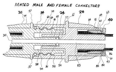
peritoneal cavity
of the patient through a catheter. The dialysate draws soluble waste and
excess fluid
from the blood contained in the numerous blood vessels in the peritoneal
membrane.
Osmosis and diffusion are the dominant mechanisms that facilitate this blood
cleansing
- 1 - File No.73927-4(OD)
CA 02574551 2007-01-19
process. In addition, the dialysate balances electrolytes and corrects
acidosis of the
blood. This entire process takes place during a fixed time period known as the
DWELL.
At the end of this period the spent dialysate is removed from the peritoneal
cavity
(DRAIN) and discarded. This exchange action must be repeated several times
during a
24-hour period because the body is continuously producing toxic wastes.
[0006] PD is a very gentle modality. Its slow corrective action closely
resembles that of
the natural kidney. The operational simplicity, the safety, the elimination of
the
venipunctures and the low operational costs continue to encourage the growth
of this
modality. Since PD is not an extracorporeal system, there is no need for large
heparinization; an advantage which favors diabetics. However, the need to
adhere to a
strict aseptic procedure to avoid infection is more important than with HD
treatment. The
peritoneum membrane is exposed to the external environment every time a
catheter is
connected to, or disconnected from the solution supply. Hence the potential
for infection
is high. This potential is a serious limitation to the wide spread acceptance
of PD and the
route of such infection can usually be traced back to the connectology
practice associated
with current PD machines.
[0007] Connectology is a dialysis term that describes the connection
relationships
between a patient's catheter, the machine disposable set (including the
transfer set), and
the solutions.
[0008] In PD, poor connectology is often the first culprit implicated in
peritonitis
infection-related events. Poorly designed connectors can lead to improper
handling and
can result in bacterial contamination and subsequent infection. Thus, the PD
connectology is one of the key factors associated with infection control and
infection
reduction. Complications due to infection may be fatal to the patient and can
easily triple
the cost of the treatment. Although serious efforts are being centered to
produce safe
connectology, as yet there is no a single complete connectology system that
effectively
addresses all the interfaces of PD system in clinical use.
[0009] Two features found in the current connectology art are the use of
spikes and
threaded connectors. Spiking into dialysis solution bags has many drawbacks,
the major
one being solution contamination. The procedure of spiking a sterile solution
bag can
- 2 - File No.73927-4(OD)
CA 02574551 2007-01-19
compromise the sterile integrity of the system. Contaminants on the spike are
directly
and immediately introduced into the main solution bag. Once introduced into
the bag, the
glucose, warm temperature and light provide excellent growth environment for
bacteria
to multiply very quickly. Eventually the contaminants would be infused into
the patient.
Infection therefore happens very often if extra care is not exercised with
spiking. A
desirable attribute of a connectology system is to remove the need to spike
the solution
bag.
[0010] Starting from the patient and moving towards the APD machine there are
a
number of threaded connectors. The first of these is the bond to transfer set.
This first
threaded connector mates directly to a titanium adapter that is inserted at
the opening end
of the patient's permanent catheter. A perfect non-leaking mating between the
titanium
adapter and this threaded connector must stay intact for 6 months or more. The
connector
further needs to be compatible with the many chemicals, electrolytes and
medications
used for PD treatments. The connector material should withstand high
sterilization
temperatures without deforming or shrinking. Its thread should not generate
major
friction and be easy to put on. It should not crack under pressure or
deteriorate with time
because of aging or chemical exposure. Lastly, the connector should come off
very
easily at the end of 6 months or more time of usage.
[0011] The next connector is bonded to the opposite end of the transfer set.
It is the most
critical of all the connectors. This connector must maintain its perfect
mating
characteristics during its entire life time. For example, during 6 months time
under a
CAPD modality of 5 exchanges a day, this connector undergoes screw-in and
screw-out a
minimum of 5,400 times. It must withstand chemical, electrolyte and medication
reactions, withstand stress and strain during connect and disconnect,
withstand heat
sterilization, provide perfect bonding to the transfer set tube, and above
all, its
performance should withstand aging and discoloration.
[0012] There are many medical connecting systems in use today. The majority
employ
different connectors of different shapes, different threads, and different
sizes for certain
applications and/or different components of the same treatment system. For
example,
one PD system uses an ordinary semi-rigid tube for the outlet of the solution
bags. This
-3- File No.73927-4(OD)
CA 02574551 2007-01-19
outlet is mated with a spike transfer set or a spike cassette set. The
transfer set is mated
with a multi-turn luer lock connector of different shapes and sizes. The luer
lock transfer
set connector has exposed fluid path that is susceptible to touch
contamination. The
transfer set tubing is made of silicone (a material normally used for long
life transfer
sets). The second connector of the transfer set is made of PVC, ABS and/or
polycarbonate. Since silicone cannot be effectively glued to any of these
materials,
ultrasonic welding is used to attach the second connector to the silicone
tubing.
However, the connector (hard material) and the silicone tubing (soft and
flexible
material) have different durometers. Therefore ultrasonic welding does not
produce
reliable bonding between the connector and the tubing. To compensate a
shrinkable
overlay is applied over the welding to help secure the tubing to the
connector. This
bonding technique often fails because of aging and repeated mechanical stress
and strain
forces during connecting and disconnecting of the transfer set during the six
months use
and disinfectants have been known to gradually degrade the bonding between the
connector and the tubing. A desirable attribute to improve the current art is
a more robust
method of chemically and mechanically joining the transfer tube to the
connector and
having an enclosed fluid path that is not susceptible to touch contamination.
[0013] The threading of the second connector of the current transfer set
requires two or
more complete rotations to fully engage and properly seal to the patient line
of the
dialysis disposable set. The twisting caused by screwing and unscrewing
procedure, if
not done well, transmits twists to the transfer set and the catheter as well.
Mechanical
stresses to the catheter due to these manipulations and/or pulling may cause
trauma to the
exit site of the catheter. This may result in exit-site infection, which is
also a major
problem of peritoneal access. For safety, the exit-site should be disturbed as
little as
possible. Trauma to the exit-site may cause leaks of dialysis solution. It is
therefore
highly beneficial to rely on a single rotation or less to securely engage a
transfer set to the
patient line of the peritoneal dialysis disposable set andlor the solution
bags.
[0014) The disposable sets are complemented by disinfecting caps that allow
patients to
disconnect from and connect to the machine during treatment or at the end of
treatment
without risk of infection. Disinfecting caps should mate well with the
connectors. The
cap should ensure that the disinfectant does not dry up during storage and/or
between
- 4 - File No.73927-4(OD)
CA 02574551 2007-01-19
patient disconnections. The caps should come off very easily when being
removed. The
cap should withstand pressure and stress. The cap should be smooth and small
enough to
provide comfort to patients wearing it for 6 months or more. The cap should be
large
enough to provide easy handling and be removed with minimum force. The design
of the
cap should be such that the patients do not touch the tip and/or the fluid
path during
handling (to prevent touch-contamination). Moreover it should be easy for the
elderly
and vision limited patients to operate safely. Preferably the mating should
produce a
positive feedback for the patient to know that the cap is properly seated onto
the
connector. Therefore an effective connectology system should incorporate
disposable
sets that are complemented by disinfecting caps to allow patients to knowingly
disconnect and reconnect safely from the machine without risk of infection
during and
after treatrnent.
[0015] It is an object of this invention to partially or completely fulfill
one or more of the
above-mentioned needs.
Summary of the Invention
[0016] According to an aspect of the present invention there is provided a
connectology
system comprising a set of mating male connectors and female connectors, the
connectors having: a) two or more independent quarter-turn threads to engage
and
disengage the connectors; b) a tactile feedback mechanism to indicate
completion of
engagement and commencement of disengagement; c) flange elements to inhibit
touch
contamination of the connectors; and d) wing elements to permit application of
torque for
engagement and disengagement.
[0017] Preferably, the male connectors and female connectors are comprised of
an inner
tube and an outer tube, wherein the inner tube forms a fluid path for the
system and the
outer tube shields the inner tube from contact and touch contamination.
[0018] Also preferably, the system further includes a set of male connector
caps and
female connector caps to cover the male connectors and female connectors when
not in
use. The system may additionally further include a set of male disinfectant
caps and
- 5 _ File No.73927-4(OD)
CA 02574551 2007-01-19
female disinfectant caps to cover and disinfect the male connectors and female
connectors when not in use.
[0019] Most preferably, the disinfectant caps contain a disinfectant which is
retained
inside the disinfectant caps when not in use and released from the
disinfectant caps when
they are connected to the connectors.
[0020] Other and further advantages and features of the invention will be
apparent to
those skilled in the art from the following detailed description thereof,
taken in
conjunction with the accompanying drawings.
Brief Description of the Drawings
[0021] The invention will now be described in more detail, by way of example
only, with
reference to the accompanying drawings of preferred embodiments of the present
invention, in which like numbers refer to like elements, wherein:
Figure 1 A is a schematic drawing of an APD set up for performing dialysis
treatment;
Figure 1 B is a schematic drawing of a set-up for performing CAPD or Manual
peritoneal dialysis;
Figure 2 is a side view of preferred transfer set according to the present
invention;
Figure 3 is side views prospective views of the preferred female and male
connectors and, the preferred female and male disinfectant caps;
Figure 4 shows elevation views of female and male covers, vented and non-
vented, with the two O-Rings, big and small;
Figure 5 is a cut-away view of a non-vented male connector cover and female
disinfectant cap showing disinfectant solution retained by porous sponge;
- 6 - File No.73927-4(OD)
CA 02574551 2007-01-19
Figure 6 is a cut-away view of a non-vented female connector cover and male
disinfectant cap showing disinfectant solution retained by porous sponge;
Figure 7 displays elevation views of the preferred embodiment of Luer Lock
connector, the retaining ring and Long Life tubing;
Figure 8 is an exploded sectional view of the female connector, the small 0-
ring,
non-vented cover and retaining ring;
Figure 9 shows in exploded sectional view the male connector, the big 0-ring
and
non-vented cover and retaining ring;
Figure 10 shows a cross-sectional view of mated male and female connectors
with
tubing attached to the female connector;
Figure 11 shows a perspective view of the preferred embodiment of female
connector;
Figure 12 shows a cross-sectional view of the preferred embodiment of a male
connector with attached tubing and the connector capped with a female
disinfectant cap;
Figure 13 shows a cross-sectional view of the preferred embodiment of female
connector with attached tubing line and the connector capped with a male
disinfectant cap; and,
Figure 14 shows a cross-sectional view of the preferred embodiment of a re-
engaged male connector and female connector after said connectors have been
disinfected using their respective mating disinfectant caps.
Detailed Description of the Preferred Embodiments
[0022] This invention comprises a connectology system for dialysis, that is a
complete
set of connectors, connector retaining rings, disinfectant caps and associated
covers that
are necessary for manufacturing, sterilizing and for administering all
peritoneal dialysis
- 7 - File No.73927-4(OD)
CA 02574551 2007-01-19
treatments in a safe and reliable manner. The preferred embodiment of the
invention
further teaches the art of attaching a connector to a tubing line to provide a
reliable
bonding structure that could withstand mechanical strains, electrolyte
degradation,
chemical agent attacks, sterilization methods (heat, gases, electron beam,
gamma rays,
etc.), disinfectant reactions and long-term. applications. It is applicable to
both CAPD
and APD treatments and also to any medical treatment applications that rely on
administering fluid to patients and/or removing fluid from patients.
[0023] Figure 1A shows a typical APD interconnection system. The typical CAPD
treatment system, as shown in Figure 1B, differs only in the number and
complexity of
parts unrelated to the connectology system. Key connectors 1, 10, 20, and 30
are used in
the like manner as shown in this diagram.
[0024] Connector 1, most commonly a titanium adapter, is attached to the
patient's
catheter (not shown). Connector 10, which is a luer lock connector, and
connector 20,
which is a female tube connector, are attached to the opposite ends of the
transfer set.
Connector 30, which is a male connector, is located at the entrance of the
patient line of a
cassette or the line that is attached to the solution bags. At the end of the
tubing line (or
lines) connected to the sterile fluid source, typically a solution bag, is
another similar
female tube connector 20a. At the outlet of the sterile solution bag (or bags,
for multiple
solution sources) is another similar male connector 30a. Alternatively, the
solution bag
outlet using connector 30a could be connected directly to the transfer set
inlet female
connector 20 to perform CAPD and/or any manual PD as it is currently
practiced.
[0025] Before the system is interconnected as shown in Figures 1A or 1B or in
a similar
manner for treatment, the individual tubing sets must be manufactured and
sterilized.
Each connector should be supplied with an appropriate connector cover. The
constructions of the respective covers take a specific form depending on the
kind of
sterilization method used. Sterilization with ethylene oxide requires that the
connector
covers be vented to allow entry of the gases into the tubing set, and
diffusion of the gases
out of the tubing set after sterilization is completed. The alternative
methods of electron
beam and gamma sterilization do not require vented connector covers. For these
two
sterilization methods, tight fit non-vented connector covers are often
preferred over
- g - File No.73927-4(OD)
CA 02574551 2007-01-19
vented connector covers. The connectology system of the preferred embodiment
of the
invention can use either vented or non-vented connector covers to allow for
either type of
sterilization to be used.
[0026] In addition to connector covers, matching disinfectant caps are
provided in the
preferred embodiment, to enable safe, easy and quick disconnection of mating
connector
parts and connector ends to be disinfected continuously during separations.
[0027] Figure 2 shows a typical transfer set with a luer lock connector 10
that mates with
the titanium adapter of the catheter (not shown), a retaining ring 11, a long
life tubing
(silicone, or polyurethane) 43, a retaining ring 40, a female connector 20,
and a
disinfectant cap 31 and its associated 0-ring 34. The assembly of these parts
into the
connectology system is discussed below. This is an exit site connection and
therefore
construction and procedures aimed at inhibiting infections originating from
mechanical
wear and tear at the point of connection are desirable.
[0028] Figure 3 shows the tubing connectors 20 and 30 in more detail. It also
shows the
corresponding disinfectant caps 21 and 31. All the components are generally
cylindrical.
The disinfectant cap 31 mates with the female connector 20. The disinfectant
cap 21
mates with the male connector 30, and so cap 21 is sometimes referred to
herein as the
female cap.. The male connector 30 and the disinfectant cap 31 (the male cap)
include
large 0-rings 34 for creating a seal as discussed below. During operations
and/or at the
end of treatment, when the male connector 30 is separated (disconnected) from
the
female connector 20, the respective disinfectant caps 21, 31 are used to
protect the ends
and the fluid paths of each connector. The female disinfectant cap 21 is a
modification of
female connector 20 and the male disinfectant cap 31 is a modification of male
connector
30. The female connector 20 and the male connector 30 have respective
outwardly
protruding flanges 67 and 57. The disinfectant caps 21 and 31 have similar
outwardly
projecting flanges 67a and 57a respectively. A rearwardly protruding
protuberance 51 is
provided at the sealing face 58 of the male connector 30, and a notch 61 is
provided on
the end edge 59 of the shield 62 of the female connector 20 to co-operate with
protuberance 51 on assembly.
- 9- File No.73927-4(OD)
CA 02574551 2007-01-19
[0029] In the preferred embodiment, each male connector 30 is constructed with
an
external quarter-turn thread 53 and female connector 20 is constructed with an
intemal
quarter turn thread 63 (see Figure 8) to co-operate therewith, making it easy
to achieve
proper mating alignment and quick engagement of the connectors. This is of
particular
importance to reduction of catheter trauma at exit sites. The major
complications of
catheter exit-site separation are leaks followed by infections. Trauma and
tension to exit-
sites must be minimized to avoid separation of catheter from the skin.
Therefore, the
exit-site must be protected from mechanical disturbances no matter how
minimal. The
quarter-turn threads 53 and 63 reduce twisting that normally generates
mechanical strains
on connector fittings, transfer sets, catheters and exit-sites.
[0030] The female connector 20 includes an inner cylindrical tube 64
protruding beyond
the end opposite from that receiving the male connector 30, and terminating in
a saw-
toothed outer ring 60 for attachment to tubing 43.
[0031] To mate the female connector 20 to the male connector 30, both
connectors are
easily held in the hand, with fingers safely behind the rectangular flanges 57
of the male
connector 30 and 67 of the female connector 20, and the male connector 30 is
inserted
into the female connector 20 to engage the threading. By twisting the two
connectors
together for one quarter turn, the two connectors 20, 30 are firmly engaged
with a tactile
feedback click when the protruberance 51 of the male connector 30 locks into
the notch
61 of the female connector 20 to provide a secure lock-in of the two
connectors. This
represents a further inventive feature, a tactile feedback mechanism that
indicates to the
user that the two parts of the connectors are appropriately mated.
[0032] Figure 4 shows the associated connector covers 22, 23, 32, and 33, and
small 0-
ring 24 and large 0-ring 34 for assembly with preferred embodiments of the
invention as
illustrated. Connector covers 32 and 22 are respectively female and male
vented
connector covers, and have ribs 35, 25 respectively in their internal surfaces
that allow
gases to flow in and out of the connectors when the connectors are capped for
gas
sterilization. Connector cover 33 is a non-vented female cover and connector
cover 23 is
a non-vented male connector cover. These have no ribs, but instead have a
smooth and
tight fitting inner lumen that closes the connector's outer surfaces with air-
tight seal for
- 1 0- File No.73927-4(OD)
CA 02574551 2007-01-19
gamma and/or electron beam sterilizations. The connector cover 22 is also used
to cover
the female disinfectant cap 21, providing a leak proof cover. Likewise the
connector
cover 33 is used to cover male disinfectant cap 31. The large 0-ring 34 sits
at the outer
circumference and at the end of the threads of both the tube connector 30 and
the
disinfectant cap 31. The small 0-ring 24 is located inside of the female tube
connector
20 only, as illustrated in Fig. 8 described below.
[0033] Figure 5 shows a cut-away view of the female disinfectant cap 21 and
the non-
vented connector cover 23. The inner cylindrical tube is removed from a female
connector 20, and the hole defined by 69 extended all the way through the body
and
terminated at the end of cylindrical tube 65 with a sealed end 66. A porous
sponge 101
retains the disinfectant solution 102 inside the female disinfectant cap 21.
Similarly,
Figure 6 displays a cut-away view of the male disinfectant cap 31, the non-
vented cover
33, large O-Ring 34, disinfectant solution 102 and porous sponge 105. The
inner
cylindrical hole 58 of a male connector is extended all the way through the
whole body to
create a single cavity, eliminating the inner cylindrical tubes 91 and 54 (see
Figure 9),
and the single cavity closed at the end of 55 by 56. This cavity is filled
with disinfectant
105 and a porous sponge (or any appropriate material with a tiny hole or holes
in the
material) is placed at the opening to contain the disinfectant inside the
cavity. The
outside large 0-ring 34 is retained. It should be noted here that other kinds
of
disinfectants (gel, crystal, solid, powder etc.) could be equally used in the
same fashion.
[0034] The corresponding disinfectant caps 21 and 31 are designed to provide
effective
disinfecting of both the fluid path and the surrounding protective shields
during periods
when connectors 20 and 30 are separated (disconnections). Touch contamination
from
handling the disinfectant caps 21 and 31 is reduced by two built-in features.
The first is a
rectangular skirt 67 that prevents fingers from sliding forward to touch the
outer shield of
the connector during the connection phase. The second is that the fluid path
and porous
sponge 101, 105 are fully recessed inside an outer shield 62 to prevent
contact between
fingers and the fluid path and sponges. In addition, the rectangular skirt 67
prevents
individual disinfectant caps from accidentally rolling off sterile trays or
surfaces.
_ 11 _ File No.73927-4(OD)
CA 02574551 2007-01-19
100351 As stated above, during separations of connectors 20 and 30 each mating
connector 20, 30 is covered with corresponding disinfectant cap 21, 31. The
cap design
ensures that the internal fluid path, the external fluid path and the inside
of the
connector's outer shield are all exposed to adequate disinfectant solution
without leaks.
It is equally important that when the disinfected mating connectors are
reunited, the
flushing that follows immediately thereafter is effective to remove the
disinfectant
solutions from the fluid path before any solution is transferred to the
patient. The design
of the connectors 20, 30 and disinfectant caps 21, 31 accomplish this
important procedure
effectively and still create a barrier to microorganisms.
[0036] Figure 7 shows the transfer set luer lock connector 10 that mates with
titanium
adapter 1 (shown in Figure 1A) of the catheter (not shown). The long life
tubing 43
passes through the retaining ring 11, and slides over the inner cylindrical
tube of 10. The
retaining ring 11 slides over the long life tubing 43 and is bonded to the
inner surface of
the outer cylindrical tube of 10. The retaining ring 11 locks into the inner
part of the luer
lock connector 10 and mechanically holds the tubing 43 in place with a strong
bonding
strength. The connector's specifications of the mating end, connector 10, the
inner thread
13, inner luer taper 14, the fluid path 18 and the tube connector 17, are
designed
following luer lock standards and specifications.
[0037] In the known art of producing a transfer set, long life tubing line is
slipped over
the tail end 17 of the luer lock connector 10. Because the long life tubing
materials
(silicone, etc) do not bond very well to the luer lock plastic materials (PVC,
ABS, Hytril,
etc.) instead of using the standard bonding methods such as high strength
glue, UV cured
glue, or cyclohexanone, ultrasonic welding is often employed to weld the long
life tubing
43 to the outer surface 17 of the tail end of the luer lock. A shrinkable
sleeve is then
applied over the welded area to protect the bond. Because the two plastic
materials are of
different durometers (hard and soft), the ultrasonic bonding is not
necessarily as strong as
would be desired for the intended long-term use of the long life transfer set.
The luer
lock connector often separates from the long life tubing line, causing leaks
and creating
means for bacterial contaminations. Therefore, users are encouraged to
minimize
movement of the welded joint. Regardless, it is common for the life of the
weld to be
shorter than the expected 6-months usage.
_ 12 _ File No.73927-4(OD)
CA 02574551 2007-01-19
[0038] In this invention a method to maintain integrity of attached tubing
line to the
connector is being demonstrated. This invention combines friction, tube line
compression, a keyed saw tooth ring, and a glued and/or welded additional
retaining ring
to combat wear and tear at this joint. The tail end of the luer lock connector
10 of this
invention is provided with an inner cylindrical tube 17, terminating with a
saw-tooth ring
71, enclosed by a longer outer second cylindrical tube 15 that terminates with
an inner
ring 70. In assembly, the long life tube 43 is slipped all the way over the
outer surface of
the inner tube 17. The retaining ring 11, preferably made of the same material
and/or
similar material with the same durometer (hardness), is slipped over tube 43
and forced
between the inner cylindrical tube 17 and the outer cylindrical tube 15,
compressing tube
43 until the inner ring 70 of the outer tube 15 locks into notch 74 of the
retaining ring 11.
At the same time, notch 75 of the retaining ring 11 also aligns itself over
the saw-tooth
ring 71 of the inner tube 17, trapping the long life tube onto the saw-tooth
ring 71 and the
end 72. The outer surface 73 of the retaining ring 11 is then ultrasonic
welded to the
inner surface 16 of the outer cylindrical tube 15 to form a strong and long
lasting
permanent bond. The three mechanical forces, friction, compressive pressure
and the
keyed saw tooth lock, act in combination with the ultrasonic weld and seals to
retain the
long life tube in place. In addition the welded section is not exposed to the
fluid carrying
path and therefore removed from chemical attacks.
[0039) Figure 8 shows an exploded view of the female connector 20, with
internally
placed small 0-ring 24, the connector cover (vented 22 or non-vented 23 from
Figure 4)
and retaining ring 40 for securing the connector 20 to a tubing line. Figure 9
shows a
similar exploded view of male connector 30, with externally placed large 0-
ring 34 and
connector cover (vented 32 or non-vented 33 from Figure 4). The retaining ring
40 for
securing the connector 20 to a tubing line is shown separated from the
connector 20. The
retaining rings could be of different materials, could take on other forms of
constructions
and other methods of attachments and/or bonding could be used to attach them
to the
respective connectors. A perspective view of the female connector 20 from the
front end
is shown in Figure 11.
[0040] With reference to Fig. 8, the female connector 20 to be secured to the
opposite
end of the long life tube 43 from that to which the luer lock connector 10 is
attached has a
- 13 - File No.73927-4(OD)
CA 02574551 2007-01-19
tube connecting end of similar design as that of luer lock connector described
above. To
attach the long life tube 43 to the female connector 20, tube 43 (not shown in
Figure 8) is
slipped over the saw-tooth outer ring 60 and over the entire outer surface of
the inner
cylindrical tube 64 until seated at the end. Using the same method explained
above, the
retaining ring 40 is slipped over long life tube 43, and forced into the
inside of the outer
cylindrical tube 65 until the inner ring 82 of the outer cylindrical tube 65
locks into the
notch 42 and the notch 43 of the retaining ring 40 lines up with the saw tooth
ring 60,
trapping the long life tube 43 in place and the inner surface 45 of the
retaining ring 40,
compressing the long life tube 43 firmly against the outer end of the inner
cylindrical
tube 64. With the retaining ring 40 locked into the outer cylindrical tube 65,
the outer
surface 41 of the retaining ring 40 is ultrasonically welded to the inner
surface of the
inner surface 81 of the cylindrical tube 65 to form a strong and secure bond.
Using this
innovative method, all connectors are similarly bonded to their respective
tubing
accordingly. The retaining ring could also be bonded with glue to the inner
side of the
outer cylindrical surfaces of the connectors where the fabricating plastic
materials are
suitable to do so. For example, cyclohexanone may be used when PVC or ABS
materials
are used to fabricate the connectors 20, 30 and the corresponding retaining
rings 40.
100411 Figure 10 shows the internal structural details of mated male connector
30 to
female connector 20. The female connector 20 shows an attached tubing line
held in
place with a retaining ring 40. The retaining ring 40 is glued or
ultrasonically welded to
the inside of the female connector 20 as shown. Another tubing line (not shown
here) is
attached to male connector 30 using a retaining ring in the same manner. This
figure also
shows the alignment of the internal structures of the two connectors 30 and
20.
[0042) The outer cylindrical cover 62 of the female connector 20 slides over
the large 0-
ring 34 of the male connector 30, tightly sealing the inside of the mated
connectors from
the outside. The inner cylindrical tube 94 of the male connector 30 engages
into the inner
cylindrical tube 68 of the male connector 20 and compresses the small O-Ring
24 of the
female connector 20 against the inner cylindrical step 27 of the female
connector 20. The
aligned internal cylindrical holes 90 of male connector 30 and 83 of female
connector 20,
define a sealed continuous internal fluid path.
-14- File No.73927-4(OD)
CA 02574551 2007-01-19
[0043] Figure 12 shows a cross-section of a disconnected male connector 30
with an
engaged female disinfectant cap 21. Screwing the female disinfectant cap 21
onto the
opened end of the male connector 30 through one quarter turn twist-locks the
two
together with a tactile feedback click. The front 91 of the inner cylindrical
tube 68
displaces inwards the porous sponge 101 of the disinfectant cap 21, thereby
liberating
sufficient disinfectant to enter the fluid path 90 of the male connector 30.
At the same
time, both the inner cylindrical tube 68 and the outer cylindrical tube 52 of
the male
connector 30, are disinfected accordingly, being continuously bathed in
disinfecting fluid.
The concentration of the disinfecting fluid surrounding the inner cylindrical
tube 68 and
the outer cylindrical tube 52 of the male connector 30 gets stronger with time
as more
disinfectant diffuses into the cylindrical space defined by the inner
cylindrical surface of
the female disinfectant cap 21. The large 0-ring provides a secure seal to
prevent leaks
of fluid to the outside.
[00441 Figure 13 shows in cross-sectional view a disconnected female connector
20 with
an engaged male disinfectant cap 31. During engagement, the inner cylindrical
tube 69
pushes inward on the porous sponge 105 of the disinfectant cap 31, releasing
disinfectant
102 into the cylindrical chambers and the fluid path 83 of the female
connector 20.
Diffusion of more disinfectant into the closed cylindrical spaces continues
with time.
The large 0-ring 34 of the disinfectant cap 31 seals the disinfectant solution
from the
outside. The disinfectant cap 31 may stay connected on to the female connector
20 for as
long as required.
[0045] The large 0-ring 34 should also give way easily to a minimum torque
when the
male disinfectant cap 31 and the female disinfectant cap 21 are being taken
off from their
respective female connector 20 and male connector 30.
[0046] Figure 14 shows a cross-section of a reconnected male connector 30 to
female
connector 20. It is to be noted that after internally flushing the reengaged
connectors 30
and 20, disinfectant solution is removed from the aligned fluid paths 90 and
83.
However, the small 0-ring 24 of female connector 20, the internal cylindrical
tube 94 of
male connector 30, and the internal cylindrical tube of the female connector
20, seal off
the fluid paths 90 and 83, from the surrounding disinfectant pool that
continues to
- 15 - File No.73927-4(OD)
CA 02574551 2007-01-19
provide aseptic protection barrier to bacteria. The large 0-ring 34 keeps the
trapped
disinfectant liquid from leaking outside the connectors.
[0047] This concludes the description of a presently preferred embodiment of
the
invention. The foregoing description has been presented for the purpose of
illustration
and is not intended to be exhaustive or to limit the invention to the precise
form
disclosed. Many modifications and variations are possible in light of the
above teaching
and will be apparent to those skilled in the art. It is intended the scope of
the invention be
limited not by this description but by the claims that follow.
- 16 - File No.73927-4(OD)