Note: Descriptions are shown in the official language in which they were submitted.
CA 02574642 2007-01-22
WO 2006/008745 PCT/IL2005/000778
APPARATUS AND METHOD FOR BREATHING PATTERN DETERMINATION
USING A NON-CONTACT MICROPHONE
CROSS-REFERENCES TO RELATED APPLICATIONS
This application claims the benefit of US Provisional Patent Application
60/590,508, filed July 23, 2004, which is assigned to the assignee of the
present
application and is incorporated herein by reference.
FIELD OF THE INVENTION
The present invention relates generally to medical devices, and specifically
to
devices that monitor and/or modify biorhythmic activity of a user.
BACKGROUND OF THE INVENTION
Physical exercise often involves modifying a multi-phase biorhythmic activity,
such as breathing. Breathing patterns display irregularities in a number of
cardiovascular
diseases, including congestive heart failure (CHF), and pulmonary diseases,
including
chronic obstructive pulmonary disease (COPD). These irregularities are known
markers
for disease-related mortality and morbidity. Typical irregularities include
Cheyne-Stokes
breathing (recurrent episodes of central apnea alternating with hyperpnea),
amplitude-
modulated breathing (periodic breathing) at a rate of about one modulation per
minute,
repeated sighs, and breathing at random amplitudes and periods. A reduction in
breathing
pattern irregularity indicates an improvement in health. The impairment of
cardiovascular
reflexes, which control blood pressure and volume in an attempt to minimize
fluctuations
in, blood supply to organs, is also clinically significant in cardiovascular
and
psychosomatic diseases.
US Patents 5,076,281, 5,800,337, and 6,090,037 to Gavish, which are
incorporated
herein by reference, describe methods and devices for modifying biorhythmic
activity by
measuring one or more variables of a user. The patents describe the generation
of a
stimulus, which is provided to the user, so as to change the biorhythmic
activity of a user
in a way that relates in a predetermined way to the monitored biorhytlimic
activity. The
'037 additionally describes a respiration sensor.
1
CA 02574642 2007-01-22
WO 2006/008745 PCT/IL2005/000778
US Patent 5,423,328 to Gavish, which is incorporated herein by reference,
describes a stress-detecting device for monitoring respiration, and, in
particular, a method
for detecting and monitoring circumferential changes in the chest or abdomen
of a user
resulting from breathing.
US Patent 6,662,032 to Gavish et al., which is incorporated herein by
reference,
describes techniques for facilitating improving health of a user, including a
first sensor,
adapted to measure a first physiological variable, which is indicative of a
voluntary action
of the user; a second sensor, adapted to measure a second physiological
variable, which is
not entirely under the direct voluntary control of the user; and circuitry,
adapted to receive
respective first and second sensor signals from the first and second sensors,
and
responsive thereto, to generate an output signal which directs the user to
modify a
parameter of the voluntary action.
US Patent Application Publication 2004/0116784 to Gavish, which is
incorporated
herein by reference, describes apparatus including a sensor, adapted to
generate a sensor
signal indicative of biorhythmic activity of a user of the apparatus, the
sensor signal
having a first characteristic, indicative of a voluntary action of the user,
and a second
characteristic, indicative of a benefit-related variable of the user.
PCT Publication WO 04/014226 to Gavish, which is incorporated herein by
reference, describes apparatus including a memory for storing a set of
computer
instructions, the memory adapted to have stored therein an initial form of a
multi-phase
biorhythmic activity pattern and an indication of a desired form of the multi-
phase
biorhythmic activity pattern, wherein a ratio of durations of two phases in
the desired
form is different from a ratio of durations of the respective phases in the
initial form, and
wherein at least one phase of the multi-phase biorhytlunic activity pattern
corresponds to
a respective phase of a multi-phase biorhythmic activity of the subject.
Intercure, Inc. (Fort Lee, New Jersey, USA and Lod, Israel) markets
RESPeRATETM, a device that utilizes some of the techniques described in the
above-
referenced patents and patent application publications. This device for
modifying
biorhytlunic activity includes an input for the respiration signal, a central
processing unit,
memory, a sound synthesizing chip, and output to earphones.
US Patent 5,734,090 to Koppel et, a1., mhich is inaorporated herein. by
reference,
describes a method and apparatus for verifying an expiratory breath flow
(e.g., for
2
CA 02574642 2007-01-22
WO 2006/008745 PCT/IL2005/000778
determining a degree of alcohol in the breath), utilizing the sonic
characteristics of a
standardized breath as a reference.
US Patent 6,726,636 to Der Ghazarian et al., which is incorporated herein by
reference, describes a voice recognition breathalyzer comprising a microphone
for
transducing spoken expression into electronic signals and a breathalyzer
sensor for
transducing a given breath content into electronic signals.
US Patent 5,509,414 to Hok, which is incorporated herein by reference,
describes
techniques for detecting air flow at the mouth and nose of a subject,
including a
transducer for converting electrical signals into ultrasound waves and vice
versa, means
for directing the ultrasound waves toward the mouth and nose of the subject
and receiving
return waves, and a detector to analyze electrical signals converted by the
transducer from
the return ultrasound waves.
US Patent 5,195,528 to Hok, which is incorporated herein by reference,
describes
an acoustic respiration detector including at least two tubular air
transmission lines having
ends which are connected to microphone elements. Close to the other ends of
the lines
are openings at which turbulence, and hence acoustic signals, are created by
the incidence
of airflow caused by respiration. A holding element secures the openings
relative to the
mouth or nose of a patient whose respiratory function is to be monitored, and
a flow-
directing element, for example formed like a face mask, directs the airflow to
the
openings. The microphone elements are connected in a bridge circuit with two
voltage
supplying leads and at least one signal lead. This arrangement is described as
suppressing
sensitivity to mechanical and acoustic disturbances.
US Patent 5,797,852 to Karakasoglu et al., which is incorporated herein by
reference, describes sleep apnea screening and/or detection apparatus for use
by a patient
breathing through the nose and/or mouth and producing an air flow into and out
of the
lungs of the patient and creating audible sounds.
US Patent 6,150,941 to Geiger et al., which is incorporated herein by
reference,
describes a stand-off, non-invasive acoustic detector for monitoring physical
activity
and/or breathing activity of children and infants.
US Patent 6,261,238 to Gavriely, which is incorporated herein by reference,
describes a method for analyzing breath sounds prvduced by a respiratory
systetn, the
3
CA 02574642 2007-01-22
WO 2006/008745 PCT/IL2005/000778
method comprising: measuring breath sounds produced by the respiratory system;
tentatively identifying a signal as being caused by a breath sound of a given
type if it
meets a first criteria characteristic of the breath sound of the given type;
and confirming
said identification if a tentatively identified signal meets a second criteria
characteristic of
the breath sound of the given type.
The following patents, all of which are incorporated herein by reference, may
be
of interest:
US Patent 4,195,626 to Schweizer
US Patent 5,678,571 to Brown
US Patent 5,596,994 to Bro
US Patent 4,883,067 to Knispel et al.
US Patent 4,798,538 to Yagi
US Patent 5,827,179 to Lichter et al.
US Patent 6,001,065 to DeVito
US Patent 5,921,890 to Miley
US Patent 5,027,686 to Ishikawa
US Patent 6,212,135 to Schreiber
US Patent 4,711,585 to Fresquez et al.
The following articles, all of which are incorporated herein by reference, may
be
of interest:
Cooke et al., "Controlled breathing protocols probe human autonomic
cardiovascular rhythms," American Journal of Physiology 274:H709-H718 (1998)
Pitzalis et al., "Effect of respiratory rate on the relationship between RR
interval
and systolic blood pressure fluctuations: a frequency-dependent phenomenon,"
Cardiovascular Research 38:332-339 (1998)
Bemardi et al., "Effect of breathing rate on oxygen saturation and exercise
performance in chronic heart failure," The Lancet 351:1308-1311 (1998)
4
CA 02574642 2007-01-22
WO 2006/008745 PCT/IL2005/000778
Mortara et al., "Abnormal awake respiratory patterns are common in chronic
heart
failure and may prevent evaluation of autonomic tone by measures of heart rate
variability," Circulation 96:246-252 (1997)
La Rovere et al., "Baroreflex sensitivity and heart-rate variability in
prediction of
total cardiac mortality after myocardial infarction," The Lancet 351:478-484
(1998)
SUMMARY OF THE INVENTION
In some embodiments of the present invention, a method is provided for
determining a set of parameters of a breathing pattern of a user using a
standard non-
contact microphone. The method comprises using the microphone to measure a
first
subset of one or more parameters of respiration by the user, and applying an
algorithm to
the first subset of parameters in order to derive a second subset of one or
more estimated
parameters of the respiration that are not generally directly measurable using
the
microphone. The second subset of parameters is typically not directly
measurable using
the microphone because sounds associated with the second subset, if any,
cannot be
detected by the microphone and/or distinguished from background noise. For
some
applications, the algorithm is applied by setting the second subset of
estimated parameters
equal to a phenomenological function of the first set of parameters.
Typically, the first subset of parameters includes active expiration time
(i.e.,
duration of active expiration) and breathing period (i.e., time between
successive breaths),
and the second subset of parameters includes inspiration time. Active
expiration time is
typically measured by detecting low-frequency sounds generated by expiratory
airflow.
The method enables the determination of inspiration time, which generally
cannot be
directly measured using a standard non-contact microphone, at least in part
because
inspiratory airflow is too quiet to be detected under normal background noise
conditions.
In some embodiments of the present invention, a method is provided for
improving biorhythrnic signal detection in the presence of potentially
variable background
signal noise. The method comprises calibrating one or more signal detection
parameters
by guiding a user through a plurality of biorhythmic activity phases, and
measuring the
biorhythmic signal during the plurality of phases. The signal detection
parameters
typically include a signal-to-noise ratio and/or filtering characteristics.
The signal
5
CA 02574642 2007-01-22
WO 2006/008745 PCT/IL2005/000778
detection parameters are used for filtering background noise from detected
biorhytlunic
signals.
In some embodiments, the biorhythmic activity includes respiration, which is
detected using a standard non-contact microphone. The user is guided to inhale
for a
certain period of time, exhale for a certain period of time, and, optionally,
to hold his
breath for a certain period of time. The signal detection parameters are
typically
calibrated by (a) determining signal characteristics of the background noise
plus the
sounds of inhalation, and the background noise plus the sounds of exhalation,
and (b)
using these signal characteristics to determine net background noise, and/or
signal
characteristics of the sounds of exhalation. Such signal characteristics of
the sounds of
exhalation are typically used to determine one or more of the signal detection
parameters.
For some applications, this method is used in conjunction with techniques for
breathing
pattern modification, such as those described in the above-mentioned patents
and patent
application publications to Gavish and Gavish et al.
These techniques for improving respiration signal detection enable the
determination of specific signal detection parameters for each user under
specific
conditions of use. Such parameters typically vary from user to user based on
the user's
individual breathing habits (such as whether the user inspires and expires
from the nose or
from the mouth, and whether the user closes his lips during inspiration and
expiration).
These techniques enable dynamic determination of signal detection parameters
during
daily life in noisy environments.
For some applications, an algorithm is implemented for evaluating one or more
parameters of a non-expiratory portion of the signal substantially
continuously. For
example, such parameters may include a duration or an amplitude of the non-
expiratory
portion. In an embodiment, these parameters are determined responsively to a
physiological constraint to which most people typically adhere. One such
constraint
reflects the body's natural tendency to keep ventilation generally constant
while
minimizing energy expended. A practical exainple of this constraint is that
following a
relatively deep breath (which transiently increases ventilation), a subsequent
breath is
typically delayed.
In some embodiments of the present invention, the techniques described herein
are
implemented using the standard non-contact microphone of a conventional
consumer
6
CA 02574642 2007-01-22
WO 2006/008745 PCT/IL2005/000778
electronics device, such as a telephone, cellular telephone, personal digital
assistant
(PDA), or portable digital audio player, which a user may have already
purchased for
other purposes. For a cellular telephone, for example, the user may speak
directly into the
microphone incorporated into the body of the phone, or, alternatively, the
user may speak
into an external microphone which plugs into the body of the phone. In
general, a
microphone may be used which is incorporated into the body of the consumer
electronics
device, or which is attached to the body of the consumer electronics device
(e.g., by wire
or wirelessly). Typically, the techniques described herein are implemented in
software
that is installed in such a device, and/or in a central location that is
accessed by the device
over a conventional wireless or wired network.
In some embodiments of the present invention, the techniques described herein
are
implemented using a non-contact microphone that is integrated into a medical
device in
fluid communication (e.g., via air or another gas) with respiration-related
airflow of the
subject. For example, the medical device may comprise a breathing mask or a
tube, such
as a tracheotomy tube.
For some applications, the breathing mask or tube are components of a
ventilator
that applies positive pressure to the lungs of the subject. The techniques
described herein
are used to detect proper performance of the ventilator, typically by
detecting active
expiration by the subject. Active expiration is typically measured by
detecting low-
frequency sounds indicative of expiratory airflow, rather than by detecting
sounds of
breathing. (In such subject, sounds of breathing often do not correlate with
expiration,
because the sounds of breathing are often affected by various constrictions in
the subject's
airways. However, low-frequency sounds indicative of expiratory airflow are
not
generally affected by such constrictions.) For some applications, the
techniques described
herein are used for non-contact monitoring of breathing during weaning from
ventilation.
In an embodiment of the present invention, the techniques described herein are
used for non-contact monitoring of breathing during use of a drug inhaler by
the subject.
For some applications, such non-contact monitoring of breathing is combined
with
techniques for modifying breathing activity of the subject, such as those
described in the
above-mentioned patent and patent application publications to Gavish and
Gavish et al.
In an embodiment of the present invention, the techniques described herein
and/or
in the above-mentioned patent and patent application publications to Gavish
and Gavish et
7
CA 02574642 2007-01-22
WO 2006/008745 PCT/IL2005/000778
al. are used to treat a subject suffering from insomnia. Insonuiia is
sometimes caused by
disordered breathing, such as fast and shallow breathing. For some
applications, insomnia
is treated using techniques described herein for detecting and monitoring
breathing, in
combination with techniques for modifying respiration-related biorhythmic
activity of the
subject described in the above-mentioned patent and patent application
publications to
Gavish and Gavish et al.
In an embodiment of the present invention, the breathing monitoring techniques
described herein are used for detecting sleep-disordered breathing, such as
sleep-
disordered breathing associated with sleep apnea or sudden infant death
syndrome (SIDS).
Typically, breath-by-breath airflow during exhalation is monitored. For some
applications, such non-contact monitoring of breathing is combined with
techniques for
modifying breathing activity of the subject, such as those described in the
above-
mentioned patent and patent application publications to Gavish and Gavish et
al.
There is therefore provided, in accordance with an embodiment of the present
invention, a method for analyzing respiration of a subject, the method
including:
using a non-contact microphone, detecting airflow sounds of the respiration,
and
converting the sounds into a signal;
analyzing the signal to determine a first set of one or more parameters of the
respiration; and
applying an algorithm to the first set of parameters to derive a second set of
one or
more estimated parameters of the respiration that are not generally directly
measurable in
the signal.
In an embodiment:
the first set of parameters includes an active expiration time and a breathing
period
of the respiration,
the second set of parameters includes an inspiration time of the respiration,
analyzing the signal includes analyzing the signal to determine the active
expiration time and the breathing period, and
applying the algorithm includes applying the algorithm to derive the
inspiration
time.
8
CA 02574642 2007-01-22
WO 2006/008745 PCT/IL2005/000778
There is fiuther provided, in accordance with an embodiment of the present
invention, a method for analyzing respiration of a subject, the method
including:
detecting airflow sounds of the respiration, and converting the sounds into a
signal;
guiding the user through a plurality of respiration phases;
analyzing the signal during the guided respiration phases, and defining one or
more parameters of a filter responsively to the analysis; and
filtering background noise from the signal using the filter having the defined
parameters.
In an embodiment, guiding the user includes guiding the user through
inspiratory
and expiratory respiration phases.
There is also provided, in accordance with an embodiment of the present
invention, a method for modifying naturally-occurring multi-phase biorhythmic
activity of
a subject, the method including:
detecting a signal indicative of the multi-phase biorhythmic activity;
analyzing the signal to determine one or more parameters of a filter;
filtering background noise from the signal using the filter having the
parameters;
at least in part responsively to the filtered signal, determining a stimulus
input
which is operative to change at least one aspect of the biorhythmic activity
of the subjcct;
and
providing the stimulus input to the subject.
For some applications, filtering the background noise includes frequency
filtering
the signal. Alternatively or additionally, filtering the background noise
includes
performing non-frequency spectral analysis on the signal in order to classify
the signal
according to one or more variables.
In an embodiment, the background noise is indicative of secondary biorhythmic
activity different from the multi-phase biorhythmic activity, and filtering
the background
noise from the signal includes filtering the secondary biorhytlun.ic activity-
related
background noise from the signal.
In an embodiment, the multi-phase biorhythmic activity includes respiration of
the
subject, and detecting the signai includes detecting the signal, indicative,.
of the=respiration.
9
CA 02574642 2007-01-22
WO 2006/008745 PCT/IL2005/000778
For some applications, the background noise includes a heartbeat-related
component of
the, signal, and filtering the background noise from the signal includes
filtering the
heartbeat-related component from the signal.
In an embodiment, filtering the background noise includes performing spectral
analysis on the signal to produce a frequency spectrum. For some applications,
performing the spectral analysis includes frequency filtering the frequency
spectrum.
For some applications, filtering the background noise includes removing non-
frequency-related noise from the signal. For some applications, the non-
frequency-related
noise includes a heartbeat-related component of the signal, and removing the
non-
frequency-related noise includes removing the heartbeat-related component of
the signal
from the signal.
There is further provided, in accordance with an embodiment of the present
invention, a method for analyzing respiration of a subject, the method
including:
using a non-contact microphone, generating a raw signal indicative of airflow
sounds of the respiration;
analyzing the raw signal to determine a first set of one or more parameters of
the
respiration; and
applying an algorithm to the first set of parameters to derive a second set of
one or
more estimated parameters of the respiration that are not generally directly
measurable in
the raw signal.
In an embodiment, applying the algorithm includes setting the second set of
one or
more estimated parameters- equal to a phenomenological function of the first
set of one or
more parameters.
In an embodiment, the first set of parameters includes a measure of breathing
amplitude of the respiration, and analyzing the raw signal includes
integrating the airflow
sounds for a breath of the respiration to determine the measure of breathing
amplitude.
For some - applications, the first set of parameters includes a measure of
breathing
amplitude of the respiration, the second set of parameters is selected from
the list
consisting of: a measure of ventilation of the subject, and a measure of
breathing
irregularity of the subject, and applying the algorithm includes applying the
algorithm to
the measure of breathing amplitude to derive the selected second set of
parameters.
CA 02574642 2007-01-22
WO 2006/008745 PCT/IL2005/000778
For some applications, the method includes analyzing at least one of the first
and
second sets of parameters to derive at least one additional breathing-related
parameter of
the subject selected from the list consisting of: breathing amplitude, a
geometrical
property of airflow of the subject, a characteristic of the airflow indicative
of pursed lips
breathing, a characteristic of the breathing indicative of relaxed breathing,
a characteristic
of the breathing indicative of passive elastic recoil of lungs of the subject,
a characteristic
of breathing with effort, and a characteristic of breathing during which the
lungs of the
subject undergo a functional change.
In an embodiment, the method includes guiding the subject to perform breathing
in a plurality of respiration phases determined at least in part responsively
to the second
set of parameters. For some applications, guiding the subject to perform the
breathing
includes treating insomnia of the subject by guiding the subject to perform
the breathing
in the plurality of respiration phases.
In an embodiment, the non-contact microphone includes a non-contact
microphone of a consumer electronics device capable of performing at least one
function
that does not facilitate analyzing respiration of the subject, and generating
the raw signal
includes using the non-contact microphone. In an alternative embodiment, the
non-
contact microphone is integrated into a medical device in fluid communication
with
respiration-related airflow of the subject, and generating the raw signal
includes using the
integrated non-contact microphone. For example, the medical device may include
a drug
inhaler, and generating the raw signal includes using the non-contact
microphone
integrated into the drug inhaler.
In an embodiment, analyzing the raw signal includes deriving an expiratory
airflow sound signal from the raw signal, and analyzing the expiratory airflow
sound
signal to determine the first set of parameters. For some applications, the
method includes
generating a real-time indication for the subject that indicates whether
expiration has been
detected.
In an embodiment, the first set of parameters includes an active expiration
time
and a breathing period of the subject, and analyzing the expiratory airflow
sound signal
includes analyzing the expiratory airflow sound signal to determine the active
expiration
time and the breathing period. For some applications, the second set of
parameters
includes an asnplitude of a non-expiratory portion of the respiratioin, and
applying the
11
CA 02574642 2007-01-22
WO 2006/008745 PCT/IL2005/000778
algorithm includes applying the algorithm to derive the amplitude of the non-
expiratory
portion of the respiration.
In an embodiment, the second set of parameters includes an inspiration time of
the
subject, and applying the algorithm includes applying the algorithm to derive
the
inspiration time.
In an embodiment, applying the algorithm to derive the inspiration time
includes
determining whether a difference between the breathing period and the active
expiration
time is greater than or equal to a first function of the active expiration
time, responsively
to a positive determination, setting the inspiration time equal to a second
function of the
difference, and responsively to a negative determination, setting the
inspiration time equal
to a third function of the active expiration time.
For some applications, determining includes determining whether the difference
between the breathing period and the active expiration time is greater than or
equal to the
active expiration time.
For some applications, setting responsively to the positive determination
includes
setting the inspiration time equal to a value within plus or minus 20% of the
difference,
such as within plus or minus 10% of the difference. For some applications, the
second
function includes a function of the difference and a phenomenological
constant, and
setting responsively to the positive determination includes setting the
inspiration time
equal to the second function of the difference and the phenomenological
constant. For
some applications, setting responsively to the positive determination includes
determining
the phenomenological constant at least in part responsively to at least one
parameter of the
first set of one or more parameters.
For some applications, setting responsively to the negative determination
includes
setting the inspiration time equal to a value within plus or minus 20% of the
active
expiration time, such as within plus or minus 10% of the active expiration
time. For some
applications, the third function includes a function of the active expiration
time and a
phenomenological constant, and setting responsively to the negative
determination
includes setting the inspiration time equal to the third function of the
active inspiration
time and the phenomenological constant. For some applications, setting
responsively to
the negative determination includes determining the phenomenological, constant
at least in
part responsively to at least one parameter of the first set of one or more
parameters.
12
CA 02574642 2007-01-22
WO 2006/008745 PCT/IL2005/000778
For some applications, applying the algorithm to derive the inspiration time
includes setting the inspiration time equal to a function of a difference
between the
breathing period and the active expiration time. For some applications,
setting the
inspiration time includes setting the inspiration time equal to a value within
plus or minus
20% of the difference, such as within plus or minus 10% of the difference. For
some
applications, the function includes a function of the difference and a
phenomenological
constant, and setting the inspiration time includes setting the inspiration
time equal to the
function of the difference and the phenomenological constant. For some
applications,
setting the inspiration time includes determining the phenomenological
constant at least in
part responsively to at least one parameter of the first set of one or more
parameters.
For some applications, applying the algorithm to derive the inspiration time
includes setting the inspiration time equal to a function of the active
expiration time. For
some applications, setting the inspiration time includes setting the
inspiration time equal
to a value within plus or minus 20% of the active expiration time, such as
plus or minus
10% of the active expiration time. For some applications, the function
includes a function
of the active expiration time and a phenomenological constant, and setting the
inspiration
time includes setting the inspiration time equal to the function of the active
expiration
time and the phenomenological constant. For some applications, setting the
inspiration
time includes determining the phenomenological constant at least in part
responsively to
at least one parameter of the first set of one or more parameters.
For some applications, the method includes analyzing the derived inspiration
time
to determine an amplitude of breathing during the inspiration time.
In an embodiment, deriving the expiratory airflow signal includes:
digitizing the raw signal to generate a digital signal;
performing spectral analysis on the digital signal to produce a frequency
spectrum;
and
filtering the frequency spectrum to eliminate frequencies outside of a range
of
frequencies associated with expiratory airflow sounds.
For some applications, filtering the frequency spectrum includes setting the
range
to be between a first frequency and a second frequency, the first frequency
between 30
and 50 Hz, and the second frequency between 100 and 200 Hz.
For some applications, filtering the frequency spectrum includes:
13
CA 02574642 2007-01-22
WO 2006/008745 PCT/IL2005/000778
guiding the subject to perform breathing in a plurality of alternating
inspiratory
and expiratory respiration phases;
using the non-contact microphone, generating a raw calibration signal
indicative
of airflow sounds of the respiration during the respiration phases;
digitizing the raw calibration signal to generate a digital calibration
signal, and
performing spectral analysis on the digital calibration signal to produce an
inspiration
frequency spectrum and an expiration frequency spectrum;
subtracting the inspiration spectrum from the expiration spectrum to obtain a
net
frequency spectrum;
determining a first frequency and a second frequency by analyzing the net
frequency spectrum; and
setting the range to be between the first and second frequencies. -
For some applications, determining the first and second frequencies includes:
setting the first frequency such that an area under a first portion of the net
spectrum having a frequency less than the first frequency is less than a first
percentage of
a total area under the net spectrum; and
setting the second frequency such that an area under a second portion of the
net
spectrum having a frequency greater than the second frequency is less than a
second
percentage of the total area under the net spectrum.
In an embodiment, deriving the expiratory airflow sound signal from the raw
signal includes filtering the raw signal to eliminate frequencies outside of a
range of
frequencies associated with expiratory airflow sounds. For some applications,
filtering
the raw signal includes setting the range to be between a first frequency and
a second
frequency, the first frequency between 30 and 50 Hz, and the second frequency
between
100 and 200 Hz.
In an embodiment, analyzing the raw signal includes setting a detection
threshold,
and deriving the expiratory airflow sound signal includes interpreting
portions of the raw
signal having a signal strength greater than the detection threshold as the
expiratory
airflow sound signal. For some applications, setting the detection threshold
includes
setting the detection threshold at a level sufficient to reduce erratic peaks
in the raw signal
that are not associated with functional breathing. For some applications,
setting the
detection threshold includes:
14
CA 02574642 2007-01-22
WO 2006/008745 PCT/IL2005/000778
digitizing the raw signal to generate a digital signal having flow values at
respective points in time, and buffering the flow values of the digital signal
over a period
of time;
transforming the buffered flow values into a histogram having a plurality of
bins;
designating one of the bins having a greatest number of points as a maximum
bin;
selecting two of the bins on opposite sides of the maximum bin;
setting a width of a noise band equal to a flow interval between the two bins;
and
setting the detection threshold responsively to a flow value of the maximum
bin
and the width of the noise band.
For some applications, setting the detection threshold includes setting the
detection threshold equal to the flow value of the maximum bin plus a product
of a
constant and the width of the noise band.
In an embodiment, the method includes detecting sleep-disordered breathing by
analyzing at least one parameter selected from: the first set of parameters,
and the second
set of estimated parameters. For some applications, the sleep-disordered
breathing
includes breathing associated with apnea, and detecting the sleep-disordered
breathing
includes detecting the apnea. For other applications, the sleep-disordered
breathing
includes breathing associated with sudden infant death syndrome (SIDS), and
detecting
the sleep-disordered breathing includes detecting the SIDS.
There is still fiuther provided, in accordance with an embodiment of the
present
invention, a method for analyzing respiration of a subject, the method
including:
generating a signal indicative of airflow sounds of the respiration;
guiding the subject to perform breathing in a plurality of respiration phases;
analyzing the signal during the guided respiration phases, and defining one or
more parameters of a filter responsively to the analysis; and
filtering background noise from the signal using the filter having the defined
parameters.
In an embodiment, generating the signal includes generating the signal using a
non-contact microphone.
CA 02574642 2007-01-22
WO 2006/008745 PCT/IL2005/000778
for some applications, the one or more parameters of the filter include a
signal-to-
noise ratio, and defining the one or more parameters includes defming the
signal-to-noise
ratio.
In an embodiment, guiding the subject includes guiding the subject to perform
breathing in a plurality of inspiratory and expiratory respiration phases. For
some
applications, guiding the subject includes guiding the subject to perform
breathing in
inspiratory, expiratory, and breath-holding respiration phases.
For some applications, defining the one or more parameters of the filter
includes:
determining signal characteristics of background noise plus airflow sounds of
inhalation, and of the background noise plus airflow sounds of exhalation;
determining net background noise responsively to the signal characteristics;
and
defming the one or more parameters of the filter responsively to the net
background noise.
For some applications, the one or more parameters of the filter include a
first
frequency and a second frequency, analyzing the signal includes:
digitizing the signal to generate a digital signal, and performing
spectral analysis on the digital signal to produce an inspiration frequency
spectrum and an expiration frequency spectrum;
subtracting the inspiration spectrum from the expiration spectrum to
obtain a net frequency spectrum; and
determining the first and second frequencies by analyzing the net
frequency spectrum, and
filtering the background noise includes eliminating frequencies outside of a
range
of frequencies defined by the first and second frequencies.
For some applications, determining the first and second frequencies includes:
setting the first frequency such that an area under a first portion of the net
spectrum having a frequency less than the first frequency is less than a first
percentage of
a total area under the net spectrum; and .
setting the second frequency such that an area under a second portion of the
net
spectrum having a frequency greater than the second frequency is less than a
second
percentage of the total area under the net spectrum.
16
CA 02574642 2007-01-22
WO 2006/008745 PCT/IL2005/000778
There is yet further provided, in accordance with an embodiment of the present
invention, a method for analyzing respiration of a subject, the method
including:
determining an active expiration time and a breathing period of the subject;
determining whether a difference between the breathing period and the active
expiration time is greater than or equal to a first function of the active
expiration time;
responsively to a positive determination, estimating that an inspiration time
of the
subject is equal to a second function of the difference; and
responsively to a negative determination, estimating that the inspiration time
is
equal to a third function of the active expiration time.
In an embodiment, determining the active expiration time and the breathing
period
includes:
generating a raw signal indicative of airflow sounds of the respiration;
analyzing the raw signal to derive an expiratory airflow sound signal from the
raw
signal; and
analyzing the expiratory airflow sound signal to determine the active
expiration
time and the breathing period.
For some applications, determining includes determining whether the difference
between the breathing period and the active expiration time is greater than or
equal to the
active expiration time.
For some applications, setting responsively to the positive determination
includes
setting the inspiration time equal to a value within plus or minus 20% of the
difference,
such as within plus or minus 10% of the difference. For some applications, the
second
function includes a function of the difference and a phenomenological
constant, and
setting responsively to the positive determination includes setting the
inspiration time
equal to the second function of the difference and the phenomenological
constant. For
some applications, setting responsively to the positive determination includes
determining
the phenomenological constant at least in part responsively to at least one
parameter of the
respiration.
For some applications, setting responsively to the negative determination
includes
setting the inspiration time equal to a value within plus or minus 20% of the
active
expiration time, such as within plus or minus 10% of the active expiration
time. For some
applications, the third function includes a function of the active expiration
time and a
17
CA 02574642 2007-01-22
WO 2006/008745 PCT/IL2005/000778
phenomenological constant, and setting responsively to the negative
determination
includes setting the inspiration time equal to the third function of the
active inspiration
time and the phenomenological constant. For some applications, setting
responsively to
the negative determination includes determining the phenomenological constant
at least in
part responsively to at least one parameter of the respiration.
There is also provided, in accordance with an embodiment of the present
invention, a method for analyzing respiration of a subject, the method
including:
generating a raw signal indicative of airflow sounds of the respiration;
defining a detection threshold by:
digitizing the raw signal to generate a digital signal having flow
values at respective points in time, and buffering the flow values of the
digital signal over a period of time,
transforming the buffered flow values into a histogram having a
plurality of bins,
designating one of the bins having a greatest number of points as a
maximum bin,
selecting two of the bins on opposite sides of the maximum bin,
setting a width of a noise band equal to a flow interval between the
two bins, and
setting the detection threshold responsively to a flow value of the
maximum bin and the width of the noise band; and
deriving an expiratory airflow sound signal from the raw signal by
interpreting
portions of the raw signal having a signal strength greater than the detection
threshold as
the expiratory airflow sound signal.
For some applications, setting the detection threshold includes setting the
detection threshold equal to the flow value of the maximum bin plus a product
of a
constant and the width of the noise band.
There is yet additionally provided, in accordance with an embodiment of the
present invention, a method including:
using a non-contact microphone integrated into a ventilator, generating a
signal
indicative of airflow sounds ,of respiration of. a s.ubj.ect;. and ,. .
analyzing the signal to detect active expiration of the subject.
18
CA 02574642 2007-01-22
WO 2006/008745 PCT/IL2005/000778
For some applications, the method includes analyzing the active expiration to
determine whether the ventilator is functioning properly.
For some applications, analyzing the signal includes analyzing a low-frequency
component of the signal to detect the active respiration.
For some applications, generating the signal includes generating the signal
during
weaning of the subject from ventilation.
There is still additionally provided, in accordance with an embodiment of the
present invention, a method including:
using a non-contact microphone integrated into a drug inhaler, generating a
signal
indicative of airflow sounds of respiration of a subject; and
analyzing the signal to detect active expiration of the subject.
For some applications, the method includes guiding the subject to perform
breathing in a plurality of respiration phases determined at least in part
responsively to the
detected active expiration.
For some applications, analyzing the signal includes analyzing a low-frequency
component of the signal to detect the active respiration.
There is yet additionally provided, in accordance with an embodiment of the
present invention, a method including:
selecting a subject suffering from insomnia;
using a non-contact microphone, generating a signal indicative of airflow
sounds
of respiration of the subject;
analyzing the signal to detect active expiration of the subject; and
treating the insomnia by guiding the subject to perform breathing in a
plurality of
respiration phases determined at least in part responsively to the detected
active
expiration.
There is still additionally provided, in accordance with an embodiment of the
present invention, apparatus for analyzing respiration of a subject,
including:
a non-contact microphone, adapted to generate a raw signal representing
airflow
sounds of the respiration; and
a control unit, adapted to:
19
CA 02574642 2007-01-22
WO 2006/008745 PCT/IL2005/000778
analyze the raw signal to determine a first set of one or more parameters of
the
respiration, and
apply an algorithm to the first set of parameters to derive a second set of
one or
more estimated parameters of the respiration that are not generally directly
measurable in
the raw signal.
There is yet additionally provided, in accordance with an embodiment of the
present invention, apparatus for analyzing respiration of a subject,
including:
a microphone, adapted to generate a signal representing airflow sounds of the
respiration;
an output generator; and
a control unit, adapted to:
drive the output generator to guide the subject to perform breathing in a
plurality
of respiration phases,
analyze the signal during the guided respiration phases, and define one or
more
parameters of a filter responsively to the analysis, and
filter background noise from the signal using the filter having the defmed
parameters.
There is also provided, in accordance with an embodiment of the present
invention, apparatus for modifying naturally-occurring multi-phase biorhythmic
activity
of a subject, the apparatus including:
a sensor, adapted to detect a signal indicative of the multi-phase biorhythmic
activity;
a control unit, adapted to:
analyze the signal to determine one or more parameters of a filter,
filter background noise from the signal using the filter having the
parameters, and
at least in part responsively to the filtered signal, determine a
stimulus input which is operative to change at least one aspect of the
biorhythmic activity of the subject; and
a stimulator, adapted to provide the stimulus input to the subject.
CA 02574642 2007-01-22
WO 2006/008745 PCT/IL2005/000778
There is further provided, in accordance with an embodiment of the present
invention, apparatus for analyzing respiration of a subject, the apparatus
including a
control unit, adapted to:
determine an active expiration time and a breathing period of the subject,
determine whether a difference between the breathing period and the active
expiration time is greater than or equal to a first function of the active
expiration time,
responsively to a positive determination, estimate that an inspiration time of
the
subject is equal to a second function of the difference, and
responsively to a negative determination, estimate that the inspiration time
is equal
to a third function of the active expiration time.
There is still further provided, in accordance with an embodiment of the
present
invention, apparatus for analyzing respiration of a subject, the apparatus
including:
a sensor, adapted to generate a raw signal indicative of airflow sounds of the
respiration; and
a control unit, adapted to:
define a detection threshold by:
digitizing the raw signal to generate a digital signal having . flow
values at respective points in time, and buffering the flow values of the
digital signal over a period of time,
transforming the buffered flow values into a histogram having a
plurality of bins,
designating one of the bins having a greatest number of points as a
maximum bin,
selecting two of the bins on opposite sides of the maximum bin,
setting a width of a noise band equal to a flow interval between the
two bins, and
setting the detection threshold responsively to a flow value of the
maximum bin and the width of the noise band, and
derive an expiratory airflow sound signal from the raw signal by interpreting
portions of the raw signal having a signal strength greater than the detection
threshold as
the expiratory airflow sound signal.
21
CA 02574642 2007-01-22
WO 2006/008745 PCT/IL2005/000778
There is additionally provided, in accordance with an embodiment of the
present
invention, apparatus for use with a ventilator, the apparatus including:
a non-contact microphone, adapted to be integrated into the ventilator, and to
generate a signal indicative of airflow sounds of respiration of a subject;
and
a control unit, adapted to analyze the signal to detect active expiration of
the
subj ect.
There is yet additionally provided, in accordance with an embodiment of the
present invention, apparatus for use with a drug inhaler, the apparatus
including:
a non-contact microphone, adapted to be integrated into the drug inhaler, and
to
generate a signal indicative of airflow sounds of respiration of a subject;
and
a control unit, adapted to analyze the signal to detect active expiration of
the
subject.
The present invention will be more fully understood from the following
detailed
description of embodiments thereof, taken together with the drawings, in
which:
BRIEF DESCRIPTION OF THE DRAWINGS
Fig. 1 is a schematic pictorial illustration of a microphone-based breathing
pattern
modification system applied to a user, in accordance with an embodiment of the
present
invention;
Fig. 2 is a schematic block diagram of the system of Fig. 1, in accordance
with an
embodiment of the present invention;
Fig. 3 is a flow chart illustrating a method for determining a breathing
pattern
from a raw analog signal, in accordance with an embodiment of the present
invention;
Figs. 4A and 4B are schematic illustrations of signals analyzed at a threshold
calculation step of the method of Fig. 3, in accordance with an embodiment of
the present
invention;
Fig. 5 is a schematic illustration of a recording of microphone-detected
airflow,
recorded using the techniques described herein, and a corresponding recording
of chest
circumference, recorded using techniques known in the art, in accordance with
an
embodiment of the present invention;
22
CA 02574642 2007-01-22
WO 2006/008745 PCT/IL2005/000778
Fig. 6 shows an exemplary correlation between a microphone-detected expiration
time and a belt-determined active expiration time, based on experimentally-
obtained data
like (but different from) the data shown in Fig. 5, in accordance with an
embodiment of
the present invention;
Fig. 7 is a graph showing experimental results measured in accordance with an
embodiment of the present invention;
Fig. 8 is a flow chart illustrating a method for adaptively determining
filtering
frequencies, in accordance with an embodiment of the present invention; and
Figs. 9A and 9B are schematic illustrations of several exemplary spectra, in
accordance with an embodiment of the present invention.
DETAILED DESCRIPTION OF EMBODIMENTS
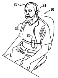
Fig. 1 is a schematic pictorial illustration of a microphone-based breathing
pattern
modification system 10 applied to a user 20, in accordance with an embodiment
of the
present invention. System 10 comprises a microphone 22 and a speaker 24, which
typically are standard components of a standard headset or telephone. System
10 further
comprises a control unit 26, which is coupled to microphone 22 and speaker 24
via a
cable or wirelessly.
Fig. 2 is a schematic block diagram of system 10, in accordance with an
embodiment of the present invention. Control unit 26 comprises an amplifier
28, an A/D
converter 30, a CPU 32, and a sound synthesizer 34. Sound synthesizer 34 is
typically
adapted to generate tones, music, and/or synthesized or recorded oral
messages.
For some applications, control unit 26 comprises a standard consumer
electronics
device, programmed in software to carry out the functions described herein.
For example,
control unit 26 may comprise a standard or pocket computer, a personal digital
assistant
(PDA), a "smart" phone, a telephone, or a cellular phone. Alternatively, at
least a portion
of the functions of control unit 26 are executed on a remote system that is
accessed by a
local device over a conventional 'wireless or wired network. Further
alternatively, control
unit 26 comprises a custom control unit produced to carry out the techniques
described
herein.
In general, a non-contact standard microphone, in a headset, desi,gned for a
human
user can detect the sound of effortless breathing from two sources: (a) sound
waves,
23
CA 02574642 2007-01-22
WO 2006/008745 PCT/IL2005/000778
typically at the frequency range of 500 to 5000 Hz, generated inside the body
and
propagated in the environment, such as speech, and (b) lower-frequency sound
waves,
which reflect turbulences generated by the airflow in the vicinity of the
microphone
during expiration and sometimes under windy conditions. Standard microphones
are
designed to detect speech, which is categorized in the frst source (a). Speech
is specific
to the user's specific anatomy, typically can be detected anywhere in the
vicinity of the
user, and may be generated during inspiration and/or expiration. Sound of the
second
source (b) is usually considered to be noise that should be minimized (see,
for example,
US Patent 4,887,693 to Plice, which is incorporated herein by reference). Such
sound is
unrelated to the user's specific anatomy, is usually restricted to expiration
only, and
generally can be detected only if the microphone is placed in the path of the
airflow.
Fig. 3 is a flow chart illustrating a method for determining a breathing
pattern
from a raw analog signal, in accordance with an embodiment of the present
invention.
Amplifier 28 amplifies a raw analog signal generated by microphone 22, at an
amplification step 100, and A/D converter 30 digitizes the amplified signal,
at a
digitization step 102. Control unit 26 buffers the digital signal, at a buffer
step 104. The
size of the buffer is determined responsive to the requirements of the
detection process.
For example, if it is desired to perform spectral analysis as described
hereinbelow every t
seconds, and if data are sampled at a sampling rate f, then the buffer should
typically be
large enough to hold at least t*f data points.
At a filtering step 106, control unit 26 periodically performs spectral
analysis on
the buffered data, e.g., every 0.05 - 1 second (such as every 0.1 seconds).
Control unit 26
typically performs the spectral analysis using a discrete Fourier transform
(DFT),
operating within a range of frequencies between a minimum frequency (finin)
and a
maximum frequency (finax). The minimum and maximum frequencies are typically
determined based on characteristics of microphone 22 and the specific
application. In
general, the maximum frequency is set such that the spectral power at
frequencies higher
than the maximum frequency is dominated by sounds not associated with the
airflow of
expiration. The minimum frequency is generally set such that the spectral
power at
frequencies lower than the minimum frequency is dominated by environmental
airflows,
e.g., wind. Typically, at filtering step 106, control unit 26 eliminates
frequencies that are
less than a frequency fl and greater athan a, frequency f2, where .fl, is,
greater than
minimum frequency finin, and f2 is less than maximum frequency finax. For some
24
CA 02574642 2007-01-22
WO 2006/008745 PCT/IL2005/000778
applications, control unit 26 determines fl and f2 using adaptive optimization
techniques
described hereinbelow with reference to Figs. 8, 9A, and 9B. Alternatively, fl
and f2 are
pre-selected (in which case the filtering is not adaptive). Typically, fl is
between about
30 and about 50 Hz, and fL is between about 100 and about 200 Hz.
At a spectrum integration step 108, control unit 26 integrates the power of
the
spectrum, and, typically, smoothes the signal using a moving-average
calculation, at a
moving average calculation step 110. The resulting temporal (i.e., non-
spectral) signal is
indicative of the microphone-detected expiratory airflow. The control unit (a)
buffers this
signal at a buffer step 112, and (b) analyzes this signal at an expiratory
airflow detection
step 114, both of which are described hereinbelow.
At buffer step 112, control unit 26 buffers the temporal signals detected
during the
N most recent breathing periods. N is determined by the pattern parameters to
assure that
the data distribution is sufficient for threshold determination. For example,
N may be
selected to include at least five detected breathing periods, as shown
hereinbelow in Fig.
4A.
At a threshold calculation step 116, using data stored at buffer step 112,
control
unit 26 calculates a detection threshold at selected time intervals, typically
using the
techniques described hereinbelow with reference to Figs. 4A and 4B. For some
applications, the detection threshold is set equal to the greater of (a) the
threshold
determined using the techniques described hereinbelow with reference to Figs.
4A and
4B, and (b) a secondary threshold determined at step 118, as described
hereinbelow. At
expiratory airflow detection step 114, control unit 26 detects the onset and
cessation of
expiratory-related airflow by analyzing the microphone-detected airflow with
respect to
the detection threshold. The control unit interprets airflow having a signal
strength
greater than the detection threshold as expiration, and airflow having a
signal strength less
than the detection threshold as background noise.
For some applications, at expiratory airflow detection step 114, control unit
26
generates a real-time indication for user 20, indicating that expiration has
been detected.
For some applications, this indication helps user 20 optimize the positioning
of
microphone 22. Alternatively or additionally, if no,respiration signal has
been detected
over a certain period of time, control unit 26 notifies user 20 that
microphone 22 should
be repositioned.
CA 02574642 2007-01-22
WO 2006/008745 PCT/IL2005/000778
At a pattern determination step 118, control unit 26 determines breathing
pattern
parameters, such as described hereinbelow with reference to Figs. 5, 6, and 7.
In order to
determine these parameters, it is desirable to have a sufficiently large
number of recent
breathing data points to process, and these are stored at buffer step 112. For
example, if it
is desired to have breathing data representative of five breaths, and if the
most recent five
breaths occurred over a 45 second period and were sa.mpled at 10 Hz, then the
buffer
should typically contain at least 450 points. (Data processing techniques as
are known in
the art may be applied to reduce this number.)
In an embodiment, use of a secondary threshold at threshold calculation step
116,
described hereinabove, reduces or eliminates erratic peaks that cannot be
associated with
functional breathing according to predetermined rules. For example, the
secondary
threshold may be used to identify erratic peaks in certain recorded signals
that are
associated with the user: (a) talking (rather than breathing), or (b) exhaling
due to a
change in posture, thereby forcing air out of his lungs (not as part of a
functional
breathing cycle).
As appropriate, control unit 26 may define and utilize one or more secondary
thresholds by: (a) defining secondary thresholds responsive to one or more
values
associated with the previous 1-5 breaths (e.g., setting a secondary threshold
to be n times
larger than the average respiration volume associated with the breaths), (b)
comparing the
corresponding parameters for the currently-recorded breathing data with the
secondary
thresholds, and (c) accepting the currently-recorded breathing data as being
indicative of
actual functional breathing if the corresponding parameters do not pass the
secondary
thresholds. For some applications, control unit 26 determines a secondary
threshold value
at pattern determination step 118 (for example by taking a percentage, e.g.,
20%, of the
most recent average flow amplitude, as reflected in the breathing pattern
and/or a series of
breaths).
Reference is now made to Figs. 4A and 4B, which are schematic illustrations of
signals analyzed at threshold calculation step 116 (Fig. 3), in accordance
with an
embodiment of the present invention. Fig. 4A shows a trace 160 of the
digitized
microphone signal stored at buffer step 112 over a 20-second period. Trace 160
is
transformed into a histogram 170, shown in Fig. 4B. Typically, this
transformation is
performed by setting the bin width of histogram 170 equal to the smallest
value that
26
CA 02574642 2007-01-22
WO 2006/008745 PCT/IL2005/000778
results in at least one bin having at least a threshold number of points n,
e.g., about 20
data points. Typically, the bin width is set such that a minimum or near-
minimum
number of the bins have at least the threshold number of points.
According to a first method for setting the bin width, control unit 26 sets an
initial,
transitional bin width to a low value, typically 1. The control unit counts
the number of
points in each resulting bin. If all the bins have fewer than n points, the
control unit
increments the transitional bin width, typically by 1, and the method loops
back to the
previous counting step. On the other hand, if any of the bins has at least n
points, the
control unit designates the bin having the greatest number of points M as a
maximum bin
172.
According to a second method for setting the bin width, control unit 26
applies a
successive-approximation procedure to the data of trace 160. The control unit
creates an
initial, transitional histogram, having a single bin having a flow data range
between 0 and
F, where F is the maximum flow value of trace 160. The control unit divides
the flow
data range into two equal flow intervals: (1) from 0 to F/2 and (2) from F/2
to F. The
control unit selects the flow interval containing the larger number of points,
and compares
the number of points in the selected flow interval to n. If the number of
points in the
selected flow interval is greater than or equal to n, the method returns to
the division step
above, at which the selected flow interval is divided into two flow intervals.
On the other
hand, if the number of points in the selected flow interval is less than n,
the control unit
typically reverses the most recent division, resulting in a flow interval
having M points,
where M is greater than or equal to n. The control unit uses the resulting
flow interval as
the bin width of histogram 170. The control unit designates the bin of
histogram 170
having the greatest number of points M as maximum bin 172.
Maximum bin 172 has a flow value (y-axis) of B. Flow value B typically
corresponds to the average flow of the background noise of the signal.
Typically, control
unit 26 selects two bins 176 and 178 on opposite sides of maximum bin 172
having
numbers of points closest to M12, and sets a width W of a noise band 180 equal
to the
flow interval between bins 176 and 178. (Instead of using M/2, as described,
for some
applications a value of M/k is used, where k is typically between 1.5 and 4.)
The control
unit typically sets a detection threshold 182 equal to (a) B plus (b) the
product of W and a
constant, for example, equal to B plus an iinteger multiple of W, e.g., B +
2W: Typically,
27
CA 02574642 2007-01-22
WO 2006/008745 PCT/IL2005/000778
control unit 26 determines detection threshold 182 substantially continuously,
resulting in
an adaptive detection process.
Reference is now made to Fig. 5, which is a schematic illustration of a
recording
250 of microphone-detected airflow, recorded using the techniques described
herein, and
a corresponding recording 252 of chest circumference, recorded using
techniques known
in the art, in accordance with an embodiment of the present invention.
Microphone-
detected recording 250 and chest circumference recording 252 were recorded
simultaneously in the same user. Microphone-detected recording 250 was
filtered using
frequencies fl and f2 of 30 Hz and 150 Hz, respectively, at filtering step
106, described
hereinabove with reference to -Fig. 3. Chest circumference recording 252 was
recorded
using a belt-type sensor similar to the belt-type sensor described in the
above-mentioned
US Patents 5,423,328 and 6,090,037 to Gavish. Because such belt-type sensors
produce
highly accurate measurements of breathing phases, chest circumference
recording 252
serves as a control for determining the accuracy of microphone-based breathing
phase
determinations using the techniques described herein.
Chest circumference recording 252 clearly shows all phases of normal
breathing:
inspiration and expiration, including active expiration and a post-expiratory
pause. Chest
circumference recording 252 is analyzed using min-max analysis to derive
inspiration
time Tin, breathing period T, expirat'ion time Tex = T - Tin, the active
expiration time
Tax, and breathing amplitude A, for example as described in the above-
mentioned US
Patent 5,800,337.
In contrast, microphone-detected recording 250 shows only the active
expiration
phase of breathing. At least an estimation of inspiration time is necessary
for certain
applications (including breathing pattern modification by generating
inspiration- and
expiration-related guiding tones, as described, for example, in the above-
referenced
patents and patent application publications to Gavish and Gavish et al.).
Reference is made to Fig. 6, which shows an exemplary correlation between
microphone-detected expiration time Tf and belt-determined active expiration
time Tax,
using the data shown in Fig. 5, in accordance with an embodiment of the
present
invention. The correlation between Tf and Tax, as determined using linear
regression, is r
= 0.98 with slope 0.97 0.05 (expected 1) and an intercept of nearly zero
(expected 0).
The accuracy in time is 0.22 seconds, where 0.14 seconds is the statistical
error in
28
CA 02574642 2007-01-22
WO 2006/008745 PCT/IL2005/000778
measuring the time interval under a 10 Hz sampling rate. A similar correlation
was found
between the microphone-detected and belt-determined breathing periods (data
not shown).
These data indicate that the microphone-detected parameters are comparable to
those
detected by a belt-type sensor.
Reference is again made to Fig. 5. In an embodiment of the present invention,
a
method is provided for estimating inspiration time Tinf using microphone-
detected active
expiration time Tf and breathing period T (time between successive breaths).
This
method is typically used for carrying out pattern determination step 118,
described
hereinabove with reference to Fig. 3. The airflow signal reflected in
recording 250
generally corresponds to the time derivative (with inverted sign) of the chest-
circumference recording 252 during expiration, because airflow is the time
derivative of
lung volume as indicated by chest circumference.
The inventors have observed that effortless breathing generally can be
characterized by one of two patterns:
= a first pattern 260, in which the end of active expiration Tax occurs
generally at the same time as the beginning of the subsequent inspiration
Tin. For this pattern, Tinf is estimated using the following formula:
Tinf =T-Tf (1)
For some applications, Tinf is set to a function of T - Tf. For example,
Tinf may be set to the product of T - Tf and a constant between about 0.8
and about 1.2, such as between about 0.95 and about 1.05. Alternatively,
Tinf may be set to the sum of T - Tf and the value, wherein the value is
positive or negative. For some applications, Tinf is set to be equal to T -
Tf within plus or minus 20%, such as within plus or minus 10%. For some
applications, Tinf is set to a phenomenological function of T - Tf, or of
other respiration-related parameters measured using techniques described
herein. For some applications, one or more constants of the
phenomenological function is determined at least in part responsively to at
least one parameter of the respiration.
= a second pattern 262, in which the end of active expiration Tax is followed
by a phase Tp with no chest movement, which is followed by the
29
CA 02574642 2007-01-22
WO 2006/008745 PCT/IL2005/000778
beginning of the subsequent inspiration Tin. For this pattern, Tinf is
typically estimated using the following formula:
Tinf = T f (2)
For some applications, Tinf is set to a function of Tf. For example, Tinf
may be set to the product of Tf and a constant between about 0.8 and
about 1.2, such as between about 0.95 and about 1.05. Alternatively, Tinf
may be set to the sum of Tf and the value, wherein the value is positive or
negative. For some applications, Tinf is set to be equal to Tf within plus
or minus 20%, such as within plus or minus 10%. For some applications,
Tinf is set to a phenomenological function of Tf, or of other respiration-
related parameters measured using techniques described herein. For some
applications, one or more constants of the phenomenological function is
determined at least in part responsively to at least one parameter of the
respiration.
The inventors have observed that in first pattern 260, active expiration time
Tax
generally has a duration greater than the duration of inspiration time Tin,
sometimes up to
5 times greater. In contrast, in second pattern 262, Tax generally has a
similar duration to
that of Tin. The inventors have observed that first pattern 260 is usually
obtained when a
user is performing an action such as pursed lips breathing, i.e., artificially
prolonging
expiration by narrowing the gap between the lips, which is a known natural
therapeutic
maneuver. Second pattern 262 reflects a general natural tendency to match the
flow at the
beginning of inspiration and expiration.
Formulas (1) and (2) can be combined and represented by the following
algorithm:
If T-Tf>_Tf
then Tinf =. T-T f
else Tinf = Tf (3)
As mentioned above, for some applications, Tinf is set to a function of T - Tf
or Tf,
depending on the evaluation of the condition. Alternatively or additionally,
the condition
evaluated by the algorithm is: If T - T f _ a function of Tf.
CA 02574642 2007-01-22
WO 2006/008745 PCT/IL2005/000778
Fig. 7 is a graph showing experimental results measured in accordance with an
embodiment of the present invention. The graph shows microphone-detected Tinf
calculated using algorithm (3) (y-axis) vs. Tin measured with a belt-type
sensor (x-axis),
with the data points randomly selected from data of 10 different users (3
breaths for each
user). The correlation between Tinf and Tin, as determined using linear
regression, is r=
0.82 with slope 0.97 0.13 (expected 1) and an intercept of nearly zero
(expected 0). The
accuracy in time is 0.54 seconds, where 0.14 seconds is the statistical error
in measuring
the time interval under a 10 Hz sampling rate. This error represents about 25%
of the
average inspiration time Tin of 2.1 seconds, and 7.8% of the average breathing
period T
of 6.9 seconds. These results are generally sufficiently accurate for the
purpose of
modifying breathing patterns by generating guiding tones. The nearly-unity
slope
between the parameters found using algorithm (3) and the belt-type sensor
suggests that
the differences are attributable to random data scattering. In an embodiment
(typically
during a breathing pattern modification procedure), the scattering is reduced
to an
acceptable level by averaging the value of T measured during multiple
breathing cycles,
~
and/or by averaging the value of Tinf measured during multiple breathing
cycles.
In an embodiment of the present invention, additional breathing parameters are
derived from the microphone-detected airflow. The airflow can be expressed as
Y(i,t),
where Y is the magnitude of airflow, i is breath number, and t is the time
extending from
the beginning of breath i until the end of breath i. The additional breathing
parameters
include:
= breathing amplitude, which is represented by the integrated airflow for a
single breath, which is given by:
Af(i) = I Y(i., t) (4)
t
The integrated airflow represents the depth of breathing for the ith breath.
(Alternatively, breathing amplitude is represented by the maximum value
of Y(i,t) over a suitable interval.)
= the geometrical properties of the airflow pattern by means of moments,
which is given by:
31
CA 02574642 2007-01-22
WO 2006/008745 PCT/IL2005/000778
I (YG' t) = (t - (ti)r) (5)
t
where:
(Y(i, t) = t)
(a) (t i) = t I , and
t
(b) n is the order of the moment.
For example, if n = 0, 1, 2, or 3, the sum corresponds, respectively, to (a)
integrated area, (b) zero by definition, (c) variance of the airflow pattern,
and (d)
asymmetry of the airflow pattern.
For some applications, breathing amplitude is determined, such as described
above, and at least one additional parameter is derived from the breathing
amplitude. For
example, the additional parameter may be: (a) a measure of ventilation (amount
of air per
unit time), such as a product of the breathing amplitude and the respiration
period, or (b) a
measure of breathing irregularity, such as relative fluctuations in breathing
amplitude
(e.g., the standard deviation of the n last breathing amplitude values,
divided by the mean
of the breathing amplitude). Breathing irregularity generally increases during
stress and
some diseases. For some applications, other characteristics of the airflow are
detected,
such as by fitting mathematical models having a physiological rationale, such
as:
= a square pulse that corresponds to uniform expiration, which characterizes
pursed lips breathing;
= a fast-rising but gradually decreasing flow followed by a post-expiratory
pause, which characterizes relaxed breathing; or
= an exponential-decay that characterizes passive elastic recoil of the lungs
against airways resistance.
For some applications, the airflow is analyzed to detect a characteristic of
breathing with effort. For some applications, the airflow is analyzed to
detect a
characteristic of breathing during which the lungs undergo a functional
change, such as
when the subject suffers from asthma, emphysema, or another condition in which
small
32
CA 02574642 2007-01-22
WO 2006/008745 PCT/IL2005/000778
airways collapse during expiration (which cannot be characterized as a simple
elastic
recoil).
Fig. 8 is a flow chart illustrating a method for adaptively determining
filtering
frequencies, in accordance with an embodiment of the present invention. For
some
applications, control unit 26 uses this method to determine filtering
frequencies fl and f2,
described hereinabove with reference to filtering step 106 of Fig. 3, when
system 10 is
used for breathing pattern modification. Typically, when system 10 is turned
on, or when
airflow is undetected for a predetermined amount of time, control unit 26
automatically
enters a metronome mode of operation. In this mode of operation, CPU 32
alternatingly
generates inspiration and expiration phase indicators, at a phase indicators
generation step
300. For example, CPU 32 may generate each inspiration phase indicator for
between
about 1 and about 5 seconds, e.g., about 2 seconds, and each expiration phase
indicator for
between about 2 and about 10 seconds, e.g., about 4 seconds. CPU 32 typically
generates
each of the phases between about 5 and about 10 times.
Responsively to the phase indicators, sound synthesizer 34 generates tones
and/or
oral messages that instruct user 20 to synchronize breathing with the
inspiration and
expiration phases, at a guide user step 302. Microphone 22 detects the
resulting user-
generated airflow, at an airflow detection step 304. Amplifier 28 amplifies
the signal, and
A/D converter 30 digitizes the amplified signal, at an amplification and
digitization step
306. At a buffer and mark step 308, control unit 26 buffers the digital
signal, and marks
the buffered signal with the phase indicator generated when the signal was
recorded.
At a filtering step 310, control unit 26 periodically performs spectral
analysis on
the buffered data, e.g., every 0.1 seconds. Control unit 26 typically performs
the spectral
analysis using a DFT, operating within a range of frequencies between finin
and finax, as
described hereinabove with reference to filtering step 106 of Fig. 3. Control
unit 26
eliminates frequencies that are less than fnvn and greater than finax. At a
spectrum
integration step 312, control unit 26 integrates the power of separate
spectrums for the
signals stored during the inspiration phase and the expiration phase,
respectively, and
typically smoothes the signals using a moving-average calculation, at a moving
average
calculation step 314. The resulting inspiration and expiration spectra are
separately
buffered at an inspiration buffer step 316 and an expiration buffer step 318,
respectively.
33
CA 02574642 2007-01-22
WO 2006/008745 PCT/IL2005/000778
Reference is made to Figs. 9A and 9B, which are schematic illustrations of
several
exemplary spectra, in accordance with an embodiment of the present invention.
Fig. 9A
shows an exemplary inspiration spectrum 350, and an exemplary expiration
spectrum 352.
At a spectra subtraction step 320 (Fig. 8), control unit 26 subtracts
inspiration spectrum
350 from expiration spectrum 352 to obtain a net spectrum 354, shown in Fig.
9B, which
is associated with expiratory airflow sounds. Control unit 26 typically
averages net
spectrum 352 over a selected number of guided breaths. At a parameter
calculation step
322, control unit 26 calculates parameters of net spectrum 352, including fl
and f2,
described hereinabove with reference to filtering step 106 of Fig. 3. The
resulting
parameters are used at filtering step 106, as described hereinabove with
reference to Fig.
3. For some applications, fl is set to a value such that the area under net
spectrum 354 to
the left of fl is rl% (e.g., 10%) of the total area under net spectrum 354,
and f2 is set to a
value such that the area under net spectrum 354 to the right of f2 is r2%
(e.g., 10%) of the
total area under net spectrum 354. As appropriate, rl may be equal or not
equal to r2.
Alternatively or additionally, control unit 26 derives other parameters of net
spectrum 354
that are used for filtering at filtering step 106 of Fig. 3.
Reference is again made to Fig. 1. In an embodiment of the present invention,
microphone 22 is integrated into a medical device in fluid communication
(e.g., via air or
another gas) with respiration-related airflow of user 20. For example, the
medical device
may comprise a breathing mask or a tube, such as a tracheotomy tube. For some
applications, the breathing mask or tube are components of a ventilator that
applies
positive pressure to the lungs of user 20. The techniques described herein are
used to
detect proper performance of the ventilator, typically by detecting active
expiration by the
user. Active expiration is typically measured by detecting low-frequency
sounds
indicative of expiratory airflow, rather than by detecting sounds of
breathing. (In such
subject, sounds of breathing often do not correlate with expiration, because
the sounds of
breathing are often affected by various constrictions in the subject's
airways. However,
low-frequency sounds indicative of expiratory airflow are not generally
affected by such
constrictions.) For some applications, the techniques described herein are
used for non-
contact monitoring of breathing during weaning from ventilation.
In an embodiment of the present invention, the techniques described herein are
used for non-contact monitoring of breathing during-use. of a dr.ug, inhaler
by the subject.
Typically, microphone 22, and, optionally, other components of system 10, are
integrated
34
CA 02574642 2007-01-22
WO 2006/008745 PCT/IL2005/000778
into the drug inhaler. For some applications, such non-contact monitoring of
breathing is
combined with techniques for modifying breathing activity of the subject, such
as those
described in the above-mentioned patent and patent application publications to
Gavish
and Gavish et al.
In an embodiment of the present invention, the techniques described herein
and/or
in the above-mentioned patent and patent application publications to Gavish
and Gavish et
al. are used to treat a subject suffering from insomnia. Insomnia is sometimes
caused by
disordered breathing, such as fast and shallow breatliing. For some
applications, insomnia
is treated using techniques described herein for detecting and monitoring
breathing, in
combination with techniques for modifying respiration-related biorhytlunic
activity of the
subject described in the above-mentioned patent and patent application
publications to
Gavish and Gavish et al.
In an embodiment of the present invention, the breathing monitoring techniques
described herein are used for detecting sleep-disordered breathing, such as
sleep-
disordered breathing associated with sleep apnea or sudden infant death
syndrome (SIDS).
Typically, breath-by-breath airflow during exhalation is monitored. For some
applications, such non-contact monitoring of breathing is combined with
techniques for
modifying breathing activity of the subject, such as those described in the
above-
mentioned patent and patent application publications to Gavish and Gavish et
al.
In an embodiment of the present invention, techniques described herein are
used in
combination with techniques for modifying biorhythmic activity of user 20.
Typically,
the biorhythmic activity includes respiration. The user is guided to inhale
for a certain
period of time, exhale for a certain period of time, and, optionally, to hold
his breath for a
certain period of time.
In an embodiment of the present invention, a method is provided for modifying
naturally-occurring multi-phase biorhythmic activity of a subject, such as
respiration of
the subject. The method comprises detecting a signal indicative of the multi-
phase
biorhythmic activity, and analyzing the signal to determine one or more
parameters of a
filter. Background noise is filtered from the signal using the filter. At
least in part
responsively to the filtered signal, a stimulus input, such as an audio and/or
visual
stimulus input, is determined which is operative to change at least one aspect
of the
biorhythmic activity of the subject, and the stimulus input is provided to the
subject. For
CA 02574642 2007-01-22
WO 2006/008745 PCT/IL2005/000778
some applications, the background noise is indicative of secondary
biorhythrnic activity
different from the multi-phase biorhythmic activity, and the secondary
biorhythmic
activity-related background noise is filtered from the signal.
For some applications, the background noise is filtered from the signal by
frequency filtering the signal. Alternatively or additionally, the signal is
filtered by
performing spectral analysis on the signal to produce a frequency spectrum.
For example,
the frequency spectrum may be frequency filtered. Further alternatively, non-
frequency
spectral analysis is performed on the signal in order to classify the signal
according to one
or more variables.
For some applications, the background noise is filtered to remove non-
frequency-
related noise from the signal, typically to eliminate a portion of the signal
that is not
relevant to determining to the stimulus input. For example, a breathing-
related signal
(e.g., monitored using a belt-type sensor) may include a heartbeat-related
component
which is noise with respect to the respiration-related component of the
signal. This
heartbeat-related component is eliminated from the signal, typically using non-
frequency-
related filtering, such as by identifying small peaks characteristic of the
heartbeats and
removing them from the signal.
As appropriate, techniques described herein are practiced in conjunction with
techniques described in the above-mentioned patents and patent application
publications
to Gavish and Gavish et al.
Although metronome stimuli and/or other instructions have generally been
described herein as including audio tones and/or oral messages, such stimuli
and
instructions may also take additional forms, such as visual display images,
e.g., text
messages (e.g., "inhale" and "exhale"), and/or dynamically changing graphical
features,
e.g., color and form. In such cases, sound synthesizer 34 and speaker 24 are
replaced with
an appropriate output generator. Alternatively, sound synthesizer 34 generates
oral
guiding messages only, rather than tones.
It will be appreciated by persons skilled in the art that the present
invention is not
limited to what has been particularly shown and described hereinabove. Rather,
the scope
of the present invention includes both combinations and subcombinations of the
various
features described hereinabove,, as well as. variations. and modifications
thereof that are
36
CA 02574642 2007-01-22
WO 2006/008745 PCT/IL2005/000778
not in the prior art, which would occur to persons skilled in the art upon
reading the
foregoing description.
37