Note: Descriptions are shown in the official language in which they were submitted.
CA 02574949 2009-04-03
RFID CABINET
BACKGROUND OF THE INVENTION
[0002] In the healthcare industry, the availability of supply products is
critical. Various systems
exist that provide tracking of product usage, quick replenishment, user
tracking, and patient
tracking for billing purposes.
[0003] In addition, closed cabinet systems exist that prevent the removal of
items without the
entry of necessary data to perform the above tracking and prevent diversion or
theft. Such a
system is particularly applicable to the expensive items that are used in an
operating room (OR)
or cath lab. However, closed cabinet systems are also applicable to the high
volume diversion of
inexpensive items that are useful outside the healthcare facility such as
batteries, bandages,
shampoos, pens etc., where the user may consider the item too small to be
considered "theft."
[0004] In developing such systems, the challenge lies in balancing convenience
and speed of
access along with entering the necessary data to identify the user, the
product and the account
number or patient. Systems that dispense an individual product in the same
manner as a candy
machine, while desirable for convenience and security, are usually too
expensive, require special
packaging, and are not flexible in terms of the various size and
configurations of product that
need to be stocked in a hospital. They are also not very space efficient,
since items are
individually spaced and housed.
[0005] The use of RFID tags on products presents an opportunity to track
individual products
without the need for expensive dispensing systems. This is particularly true
of expensive product
where it is worth incurring the additional expense of applying the RFID tags.
RFID tags are not
currently available on products like bar codes, and are not likely to be
generally available on
healthcare products for many years.
BRIEF DESCRIPTION OF THE DRAWINGS
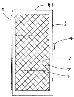
[0006]Fig. 1 is a perspective view of one embodiment of the present invention.
CA 02574949 2007-01-24
WO 2006/014813 PCT/US2005/026100
[00071 Fig. 2 is a side view of the embodiment of Fig. 1.
[0008] Fig. 3 is a perspective view of another cabinet according to the
invention.
BRIEF SUMMARY OF THE INVENTION
[0009] The invention provides both methods and apparatus for tracking,
monitoring,
protecting and safeguarding an inventory of products in a medical environment
using RFID
tags. In general, a cabinet is provided, the cabinet is constructed of a
material sufficient to
confine an RFID field generated from an RFID detector within the interior of a
cabinet. The
RFID detector scans the RFID tags of all products within the cabinet and
generates an up-to-
the-second inventory list of all products within the cabinet.
[0010] One particular aspect of the present invention provides a cabinet for
housing an
inventory of products in a medical environment. Each product within the
cabinet is furnished
an RFID tag that is unique to each product. The cabinet contains an RFID
detector that
generates an RFID field to scan the RFID tags of any product within the
interior of the
cabinet. A computer is coupled to the cabinet using Ethernet or a similar
connection. The
computer controls access to the cabinet and also coinmunicates with a database
having all the
product information associated with each product's RFID tag.
[0011] In another aspect of the invention, the locking front door and the side
panels of the
cabinet are constructed of a transparent material such that the user may see
into the cabinet
without having to unlock and open the locking front door. The transparent
material is
manufactured to sufficiently contain the RFID field generated by the RFID
detector within
the interior of the cabinet. In one embodiment, the transparent material is an
acrylic panel
that has a coating comprising a number of vertical stripes of a silver based
conductive ink and
a number of horizontal stripes of a carbon based conductive ink arranged in a
checlcerboard
pattern.
DETAILED DESCRIPTION OF THE INVENTION
[0012] Described below are several exemplary embodiments of the invention.
Although
certain features are described, for ease of discussion, in relation to certain
illustrated
embodiments, those skilled in the art will appreciate, based on the disclosure
herein, that
various of the inventive features can be combined in accordance with many
different
embodiments of the invention. The illustrated embodiments below, therefore,
are provided
merely by way of example and should not be considered to limit the scope of
the invention,
which is defined only by the appended claims.
2
CA 02574949 2007-01-24
WO 2006/014813 PCT/US2005/026100
[0013] One aspect of the invention provides a cabinet witl7 a locking door, or
multiple
individually controlled doors. In another aspect, the invention may provide a
room (or
multiple rooms) with an electronically controlled lock. The cabinet or room
may contain
multiple quantities of multiple items.
[0014] Certain items require specific shelving fixtures because certain items
contain a
liquid or metal content that prevents the transmission of sufficient signal
strength to various
tags on the products. Shelving fixtures are designed specifically for those
items, or classes of
items, to keep them suitably spaced apart. The spacing allows the RFID field
to sufficiently
energize all the tags in the system.
[0015] An RFID detector (or multiple detectors) is placed within the interior
of the cabinet.
RFID detector provides continuous monitoring of the items witllin the cabinet,
e.g.
identifying the data embedded on the tag of each product. The RFID detectors
are capable of
repeatedly scanning all products in a short time period, preferably less than
two seconds. The
system determines when an item has been removed by comparing the resulting
list of items
present with a previously generated item list. Since the scanning time period
is preferably
short, the invention provides any alerts prior to the user leaving the
vicinity of the cabinet and
the controlling computer.
[0016] The method of the present invention is preferable to existing systems,
for example
systems that detect an item being moved through a detecting portal area. In
existing systems,
any detection errors result in cumulative persistent errors that can only be
corrected by a
manual cycle count. The present invention avoids such errors by repeatedly
taking an
inventory of all products. In effect, the present invention is a repeated
electronic full cycle
count.
[0017] For multiple readings of RFID tags (and associated inventory) within a
cabinet, it is
advantageous to change the power distribution during each scan so that
different power fields
sweep the cabinet. Changing the power distribution provides additional and
differentiated
coverage, which also boosts the read accuracy.
[0018] In accordance with the present invention, the data associated with the
RFID tag may
take many forms. In one example, the invention uses a fixed ID number that is
unique to the
universe of tags used for all time. At an appropriate point in time, either at
the cabinet or a
separate workstation or system in central supply, this unique number is read
into a database.
3
CA 02574949 2007-01-24
WO 2006/014813 PCT/US2005/026100
Other data regarding the product is also entered into the database for
subsequent retrieval.
This data may include the item type ID, its UPN, expiration date, serial
number, manufacturer
or other parameters.
[0019] In another example, the RFID tags are WORM (write-once, read many)
tags. In the
case of a WORM tag, some or all of the data may be written once on the
readable memory of
the tag and thus can be read directly off the RFID tag. If the central
database is unavailable,
the product can still be identified. In addition, if access to the central
server is unavailable,
any user alerts given at the time of removal can be made by the local computer
and cabinet
system.
[0020] In yet another example, the RFID tag utilizes a writable tag. For a
writable tag,
information may be added to the product by the user. For example, the writable
tag may
contain information selected by the user such as the ID of the patient, the
user ID, the date
and time of removal, and the like. In all cases, the data formats associated
with the tags
should be compatible with the software systems, so that accurate reporting
down to the item-
level detail can be automated.
[0021] Figures 1 and 2 illustrate one example of a cabinet in accordance with
the present
invention. Cabinet 1 comprises a housing frame with locking doors 2, with
hinges 3, handles
4 and indicator lights 5. Transparent material 6 in the doors 2 allows the
user to see through
to the item on the shelves 8, but mesh 7 prevents the radio frequency from the
transmitter
receiver assembly 9 mounted on the inside rear of the cabinet from propagating
outside the
cabinet. In another embodiment, the mesh might be replaced by a translucent
coating on the
glass or plastic transparent material of the door.
[0022] Cabinet 1 may be manufactured of any material. However, it is desirable
to
manufacture cabinet 1 of a metal to contain the RFID field inside the cabinet.
Preferably, the
types of metals that may be used are steel, although aluminum may also be
used. The front
door and sides may be transparent to allow the user to see the products inside
the cabinet.
The front door may include a thermal printer that can provide a paper record
of the item taken
out from the cabinet. Within the cabinet, it will often be preferable to use
non-metal
components for shelving and partitions in order to not interfere with the RFID
field.
[0023] A wire mesh can be used as a shield to contain the RFID field within
the cabinet
while maintaining the desired level of transparency. The maximum diameter of
the holes in
4
CA 02574949 2009-04-03
the mesh is dictated by the frequency of the RFID field used. In the
alternative, a conductive film in the
pattern of a mesh may be coated on the transparent surfaces of the doors,
either as a thin translucent layer
or as an opaque coating. This arrangement provides the necessary containment
of the RFID field within
the cabinet while allowing the user to see inside the cabinet. More
particularly, a regular acrylic panel,
and coated a first pass in the vertical orientation with silver based
conductive ink in stripes, one-half inch
on center, the stripes having a width in the range of .05 to .25 inches. Then,
in the horizontal direction,
with carbon based conductive ink in stripes, half inch on center, the stripes
having a width in the range of
.05 to .25 inches. Without any specific ground connections, the resulting
checkerboard pattern of vertical
silver based conductive ink stripes and horizontal carbon based conductive ink
stripes contains the RFID
field such that the RFID tags associated with items are not read outside the
cabinet, while retaining the
visibility of the contents of the cabinet.
[0024] The use of effective shielding allows for the use of a single powerful
energizer and receiving
antenna within the cabinet. The use of a single, more powerful energizer and
receiving antenna provides
reliable detection and a cost effective solution relative to the prior art
that use multiple energizers and
antennas of shorter range in each shelf or section of a larger cabinet.
[0025] A computer 10 controls access to the interior of the cabinet by
unlocking and opening the locked
front door. Typically, there will be multiple doors, and only the applicable
door will be opened according
to the level of access associated with the user's ID. This ID may be provided
by a variety of means
including an RFID badge, a personal identification number, a voice command, a
biometric scan, a
magnetic card, a barcode badge read or the like depending upon the particular
requirements of the cabinet.
[0026] It is preferable to use a guiding light to locate the correct cabinet,
door and in some cases actual
location of the product. By using guiding lights, it is preferable to flash
all lights on a cabinet for a few
seconds, then on a door or shelves and then down to the item. Such a method is
described in U.S. Patent
Nos. 5,745,366, 5,805,455, 5,805,456, 6,039,467, 6,272,394, and 6,385,505.
[0027] The computer may be either embedded within the interior of the cabinet
or in close proximity to
the cabinet, and coupled to the cabinet by Ethernet, wireless, optical infra-
red, serial cable, USB.or any
other data connection means. One advantage of not having the
CA 02574949 2007-01-24
WO 2006/014813 PCT/US2005/026100
computer embedded within the interior of the cabinet is the use of general-
purpose computers
with varying form factors. The type, size, shape and/or configuration is
unconstrained by the
cabinet design. As software rapidly evolves for the cabinet control, newer
versions often
need a new operating system and these in turn need a new computer. By keeping
the
computer external, upgrading both software and computer hardware is both easy
and
inexpensive.
[00281 In accordance with another aspect of the present invention, the user
accesses the
cabinet using a user ID and password, an RFID badge, a bar code, a mag card or
various
biometrics such as a thumbprint, face recognition or the like. Typically, the
particular ID
device is located at the user login location or the computer interface.
However, in some
embodiments, particularly those detecting the RFID badge of a user, the
identification of a
user occurs at the cabinet. One method of authorization would allow the user
to approach the
cabinet and have the cabinet recognize the user and unlock the cabinet doors
without any
action by the user. Such quick recognition presents the ultimate in
convenience to busy
clinicians where time is a critical factor, such as physicians, and OR nurses
requiring items
during a case.
[0029] The user may or may not be required to select a patient identification
or cost center.
Instead, accounting for an item may be determined by: 1) the location of the
equipment (e.g.
the account number for supplies for the OR department in which the equipment
is located); 2)
identifying the user and associating that user with a department; 3)
association to a case by
way of the user and the time of day, since the case management system will
usually know
which users are working on which case; or 4) association to a case and/or
patient by use of an
identifier such as a mag card or and RFID card. The RFID cards may have a case
or patient
number encoded on them. Alternatively, these cards may have a permanent ID
that is
temporarily associated at the beginning of the day with the patient or case
for that day.
[0030] There may be governmental / regulatory requirements regarding access to
certain
contents in the cabinets. The user access rules accommodate and authenticate
any unique
access requirements. For example, the user may be prompted to scan a bar code
or otherwise
enter information about the product or push a button assigned to a selected
item. The user
may enter the name(s) or an alias naine(s) for a product(s) at the computer.
The computer
can generate a visual picture of the layout of the cabinet, highlighting where
the product(s) is
6
CA 02574949 2007-01-24
WO 2006/014813 PCT/US2005/026100
(are) located within the interior of the cabinet. A visual picture is useful,
since, for cost
reasons, there may be no lights to guide the user to a specific door.
[0031] Although the advantage of RFID is that an item removal is recorded with
no action
from the user, many facilities have cabinets currently in place where the
removal of an itein is
recorded by scanning a barcode, pushing a button, or keying an item ID. There
are
considerable advantages in combining existing apparatus and methods with the
apparatus and
methods of the present invention. Existing cabinets are upgraded utilizing
aspects of the
present invention to accommodate RFID tags. In initial introduction, before a
process is fully
set up to tag and identify items, a mixed system may be needed. For cost
reasons, it may be
desirable to stock low cost items that are used in association with high cost
items (e.g. gauze
pads, tubing, gloves and the like) in the same location. While it may not be
worth RFID
tagging the low cost items, their use should be recorded to track inventory
levels and ensure
prompt re-ordering.
[0032] Depending on the user's access privileges, one or more of the doors on
the cabinet
unlock upon successful completion of the entry requirements at the computer
user interface.
It is desirable to temporarily disable the RFID reader when the door is opened
so that an item
removed but held near the open door is not mistakenly interpreted by the
system as an
unremoved item. The user then removes or returns the items from or to the
opened
compartments.
[0033] If the computer is remote, then a sound and/or visual sensor at the
cabinet may alert
the user to check the monitor of the computer after removing a product. The
alert tells the
user that the computer has determined that further action is needed in
addition to the removal
of the product, such as 1) entering of a serial nuinber or other information
into the computer;
2) reading of such information using a bar code scanner mounted at the cabinet
or at the
computer; or 3) alerting the user that an expiration date for the product may
have occurred.
Preferably, these "sounds" will be recorded speech to clearly instruct the
user as to what is
needed such as "please scan the serial number and expiration date". In many
cases, it is
preferable to use text to speech since this allows information specific to the
item to be
included. For example, "You just removed a Cordis 78 French Catheter. Please
check that
this is the right item."
7
CA 02574949 2007-01-24
WO 2006/014813 PCT/US2005/026100
[0034] A particularly useful text to speech function is to state the quantity
on hand. To the
degree a system can be in error, the correction of the quantity on hand
ensures timely
restocking and the availability of product to the caregiver at all times. For
example the system
might say "You just removed a Medtronic 8F Guiding Catheter. There should be
three
remaining. If not, please correct the inventory level."
[0035] Another useful query is an automated speech to the user asking " Did
you get what
you needed? If NOT, then, please press 1- If YES, then, no response is
necessary." Such a
query provides a view into the product usability and customer satisfaction.
[0036] Typically, items are placed on the shelves in fixed locations according
to the
identity of the product using a labeling system. The current quantity on hand
for each type of
item is tracked by the embedded or local PC, and may be transmitted to a
central server. The
system generates a restock list any time the quantities of particular items
drop below a
predetermined par level. Since different items may be restocked from different
sources, the
system needs to be able to identify different restock lists for those sources.
[0037] There may be times when, the item removed from the cabinet cannot be
returned to
the cabinet without additional processing. For example, some regulated items
may not be
returned to the cabinet by the user without additional authorization and
verification. Also,
some items may have a limited, out-of-cabinet life and may need some
verification that the
item was not exposed to adverse environment.
[0038] Some authorization and verification may be local, but some may be
remote. If
local, then it is appropriate to use a "fill-or-kill" method where the next
time a restock request
is generated comparing par level with actual quantity on hand, no memory of
any previous
unfulfilled orders is retained. For other products, particularly those ordered
outside, it is
necessary to track what has been previously ordered, and subtract that from
any new
coinparison of par level minus the current on hand order quantity, but also to
net out previous
orders that are delivered over time.
[0039] When an order is placed with a specific source of material, it is
important that the
cabinet location receives information regarding what was ordered and order
identification
number. Therefore, when the restock technician comes to the cabinet after
receiving the item
for that order, he/she can select the appropriate restock order list by
entering (or bar coding or
RFID scanning) the number of the restock list. This action allows the computer
to register
8
CA 02574949 2007-01-24
WO 2006/014813 PCT/US2005/026100
the items that have been brought and the quantities being put away. If this
procedure is
omitted, the restock technician must select each item in the computer and
enter the quantity
they are restocking.
[0040] The cabinet restock process is easy with the system of the present
invention in
place. The restock person simply enters their ID and adds the items to the
cabinet. In an
alternate approach, the user is required to identify a restock list with the
associated items. In
this case, when he/she adds the items to the cabinet, a sllortage list may be
produced. A
shortage list is useful when relying on an outside fulfillment house to
deliver and restock the
cabinet, since this will detect diversion of product between the time it was
picked in the
remote warehouse and when it reached the cabinet. More particularly, since the
restock
person knows there will be a check, there is less temptation to divert product
for one's
personal consumption.
[0041] With cabinet RFID reading device set up on an Ethernet network, either
directly or
through a local compute controlling access to the cabinet, the material
manager can connect
to the reader or cabinet computer database, and get an up to the second
inventory of items
contained within the cabinet through the Inventory Control Module software.
This can be an
automated process that enables the RFID Readers to scan items in the remote
cabinet and to
alert the staff if any items are critically low or out of stock.
[0042] If a caregiver needs a particular item that is not stocked in the
cabinet in their
department, they can use the care giver software to check other RFID enabled
cabinets on the
network to find the item they needs and how many are actually on hand in that
cabinet, all in
real time.
[0043] With access to the cabinet information derived in real time through the
RFID reader,
or the computer database supporting the RFID reader, the materials manager can
scan the
RFID cabinets for items that are past their expiration date or items that are
in a lot that has
been recalled so they can be collected for return to the manufacturer. It is
particularly
important to get this infonnation in real time, since items may have been
taken then
subsequently returned etc, and in previous systems the associated information
(lot # serial
number) had to be tracked at each step. Using RFID, you essentially have
instant inventory
review - fresh instantaneous reading of exactly what is in each location, not
a deduction of
what is in each location as a result of manual recordings of takes, returns,
etc., which over
9
CA 02574949 2007-01-24
WO 2006/014813 PCT/US2005/026100
time can be incorrect if any step in the recording process is missed.
[0044] Fig. 3 illustrates another cabinet 20 having RF shielding 22 on its
outer walls 24 and
doors 26. Hence, items 28 that are disposed within cabinet 20 may be scanned
while within
cabinet 20, with the RF signal being contained within the cabinet.
[0045] Cabinet 20 may be configured similar to the other embodiments described
herein
and they may optionally have locks on the doors and may be divided into
multiple
compartments for holding multiple items. Further, one or more RFID detectors
may be
placed within the interior of the cabinet to identify data embedded on the tag
of each product.
Further, cabinet 20 may include a computer or controller for controlling
operation of the RF
signals and for processing the data transmitted from the product similar to
other embodiments
described herein.
[0046] The invention has now been described in detail for purposes of clarity
and
understanding. However, it will be appreciated that certain changes and
modifications may
be practiced within the scope of the appended claims.