Note: Descriptions are shown in the official language in which they were submitted.
CA 02575098 2012-02-22
- 1 -
APPARATUS FOR INJECTING SOLID
PARTICULATE MATERIAL INTO A VESSEL
TECHNICAL FIELD
The present invention provides a metallurgical
lance which extends into a vessel for injecting solid
particulate material into a vessel. Apparatus of this
kind may be used for injecting metallurgical feed material
into the molten bath of a smelting vessel for producing
molten metal, for example by a direct smelting process.
A known direct smelting process, which relies on
a molten metal layer as a reaction medium, and is
generally referred to as the HIsmelt process, is described
in International application PCT/AU/96/00197 (WO 96/31627)
in the name of the applicant.
The HIsmelt process as described in the
International application comprises:
(a) forming a bath of molten iron and slag in a
vessel;
(b) injecting into the bath;
(i) a metalliferous feed material, typically
metal oxides; and
(ii) a solid carbonaceous material, typically
coal, which acts as a reductant of the
metal oxides and a source of energy; and
(c) smelting metalliferous feed material to metal in
the metal layer.
The term "smelting" is herein understood to mean
thermal processing wherein chemical reactions that reduce
metal oxides take place to produce liquid metal.
The HIsmelt process also comprises post-
combusting reaction gases, such as CO and H2, released from
CA 02575098 2012-02-22
- 2 -
the bath in the space above the bath with oxygen-
containing gas and transferring the heat generated by the
post-combustion to the bath to contribute to the thermal
energy required to smelt the metalliferous feed materials.
The HIsmelt process also comprises forming a
transition zone above the nominal quiescent surface of the
bath in which there is a favourable mass of ascending and
thereafter descending droplets or splashes or streams of
molten metal and/or slag which provide an effective medium
to transfer to the bath the thermal energy generated by
post-combusting reaction gases above the bath.
In the HIsmelt process the metalliferous feed
material and solid carbonaceous material is injected into
the metal layer through a number of lances/tuyeres which
are inclined to the vertical so as to extend downwardly
and inwardly through the side wall of the smelting vessel
and into the lower region of the vessel so as to deliver
the solid material into the metal layer in the bottom of
the vessel. The lances must withstand operating
temperatures of the order of 1400 C. within the smelting
vessel. Each lance must accordingly have an internal
forced cooling system to operate successfully in this
harsh environment and must be capable of withstanding
substantial local temperature variations.
U.S. Pat. No. 6,398,842 discloses one form of lance
which is able to operate effectively under these
conditions. In that construction the solid particulate
material is passed through a central core tube which is
fitted closely within an outer annular cooling jacket, the
forward end of the core tube extending through and beyond
the forward end of the cooling jacket into the
metallurgical vessel.
CA 02575098 2012-02-22
- 3 -
It has been found in operation that on plant
shut down following a smelting operation the accretion of
lag on the lances within the vessel and on the adjacent
areas of the vessel wall can make withdrawal of the lances
very difficult. In particular the slag forms a bond
between the lance and the wall of the vessel and the slag
accretions on the lance can be larger than the opening
through it which needs to be withdrawn, making it
necessary to wait for the vessel to cool sufficiently to
enable slag breaking equipment to be brought into the
vessel. The present invention provides a modified
apparatus and a method which facilitates lance withdrawal.
DISCLOSURE OF THE INVENTION
The invention provides smelting apparatus
comprising a smelting vessel having a shell enclosing an
internal space of the vessel and a solids injection lance
extending through an opening in the shell of the vessel
into the interior space of the vessel, said solids
injection lance including a central core tube through
which to pass solid particulate material into the vessel
and an annular cooling jacket surrounding the central core
tube throughout a substantial part of its length and
provided with internal water flow passages for flow of
cooling water therethrough, wherein the solids injections
lance further comprises an annular lance mounting part
extending around the annular cooling jacket at a position
spaced back from a forward end of the lance to form at
that position a lance segment of increased cross sectional
size compared to that part of the lance which extends
forwardly from it, the vessel shell is provided with a
lance mounting tube extending outwardly from the vessel
about said opening, and the lance mounting part is
received within the mounting tube and extends into or
through the opening in the shell, wherein the vessel
CA 02575098 2014-03-14
, .
- 3a -
further comprises of releasable fastening means to fasten
the lance to the lance mounting tube such that when
released the lance can be driven inwardly of the vessel
for a distance by sliding of the annular lance mounting
part within the mounting tube.
CA 02575098 2007-01-25
WO 2006/010210 PCT/AU2005/001103
- 4 -
There may be releasable fastening means to
fasten the lance to the lance mounting tube with the
forward end of the lance mounting part extended through
said opening in the shell.
The vessel shell may be internally lined with
refractory material forming an internal surface of the
vessel and the forward end of the lance mounting part may
extend through the shell opening to a forward end
generally flush with the refractory of said internal
surface.
The internal surface of the vessel may be a
surface of a water cooled refractory panel fitted to the
vessel wall.
The lance mounting tube may extend outwardly and
upwardly from an upright part of the vessel wall and the
forward end of the mounting section may be inclined at an
angle to a central longitudinal axis of the lance so as to
be flush with an upright inner surface of the vessel.
The annular mounting part might have an outer
diameter which is at least one and a half times the outer
diameter of the annular cooling jacket of the lance. It
may be of the order of twice the diameter of the cooling
jacket.
The releasable fastening means may be such that
when released the lance can be driven inwardly of the
vessel for a distance by sliding of its mounting part
within the mounting tube.
The invention further provides a method of
operating a direct smelting plant which includes a
metallurgical vessel and one or more solids injection
lances for injecting solids material into the vessel, said
CA 02575098 2007-01-25
WO 2006/010210 PCT/AU2005/001103
- 5 -
method comprising locating each lance so as to extend into
the vessel through an opening of a size larger than the
cross section of that part of the lance within the vessel
by a lance mounting of a size to fit the opening,
conducting a smelting operation within the vessel such
that slag adheres to the lance and the internal wall of
the vessel and at the conclusion of the smelting operation
removing the lance by steps which include driving the
lance with its mounting inwardly of the vessel to break
slag accretions in the vicinity of the opening and
withdrawing the lance through the opening.
The lance mounting may be fitted within a lance
mounting tube extending outwardly from the vessel and the
lance may be driven inwardly by application of a portable
hydraulic power device between the mounting of the lance
and the mounting tube.
BRIEF DESCRIPTION OF THE DRAWINGS
In order that the invention may be more fully
explained, particular embodiments will be described in
some detail with reference to the accompanying drawings in
which:
Figure 1 is a vertical cross section through a
metallurgical vessel incorporating solids injection lances
constructed in accordance with the invention;
Figure 2 is a longitudinal cross-section through
one of the solids injection lances for injecting coal into
the vessel;
Figure 3 is a cross-section through a rear part
of the lance shown in Figure 2;
CA 02575098 2012-02-22
- 6 -
Figure 4 is a longitudinal cross-section through
part of an inner core tube assembly of the lance shown in
Figure 2;
Figure 5 is a longitudinal cross-section through
a lance for injecting hot ore material into the vessel;
Figure 6 is a cross-section through a rear part of
the lance shown in Figure 5; and
Figure 7 illustrates a modified injection lance
extended through a water cooled panel fitted to an inner face
of the vessel wall.
DETAILED DESCRIPTION OF THE PREFERRED EMBODIMENT
Figure 1 illustrates a direct smelting vessel
suitable for operation by the HIsmelt process as described
in International Patent Application PCT/AU96/00197. The
metallurgical vessel is denoted generally as 11 and has a
hearth that includes a base 12 and sides 13 formed from
refractory bricks; side walls 14 forming a generally
cylindrical barrel which extends upwardly from the sides
13 of the hearth and which includes an upper barrel
section 15 and a lower barrel section 16; a roof 17; an
outlet 18 for off-gases; a forehearth 19 for discharging
molten metal continuously; and a tap-hole 21 for
discharging molten slag.
In use, the vessel contains a molten bath of
iron and slag which includes a layer 22 of molten metal
and a layer 23 of molten slag on the metal layer 22. The
arrow marked by the numeral 24 indicates the position of
the nominal quiescent surface of the metal layer 22 and
the arrow marked by the numeral 25 indicates the position
of the nominal quiescent surface of the slag layer 23.
The term "quiescent surface" is understood to mean the
CA 02575098 2007-01-25
WO 2006/010210
PCT/AU2005/001103
- 7 -
surface when there is no injection of gas and solids into
the vessel.
The vessel is fitted with a downwardly extending
hot air injection lance 26 for delivering a hot air blast
into an upper region of the vessel and a series of solids
injection lances 27 extending downwardly and inwardly
through the side walls 14 and into the slag layer 23 for
injecting iron ore, solid carbonaceous material, and
fluxes entrained in an oxygen deficient carrier gas into
the metal layer 22. The position of the lances 27 is
selected so that their outlet ends 28 are above the
surface of the metal layer 22 during operation of the
process. This position of the lances reduces the risk of
damage through contact with molten metal and also makes it
possible to cool the lances by forced internal water
cooling without significant risk of water coming into
contact with the molten metal in the vessel.
Lances 27 may be of two kinds, a first of which
is employed to inject hot ore material and the other of
which is employed to inject carbonaceous material such as
coal. There may for example be eight solids injection
lances 27 spaced circumferentially around the vessel and
consisting of a series of four hot ore injection lances
and four coal injection lances spaced between the hot ore
injection lances. All of the lances may fit within outer
housings of a common construction but the two kinds of
lance have differing interior construction because of the
vastly different temperature of the hot ore and the coal
being injected.
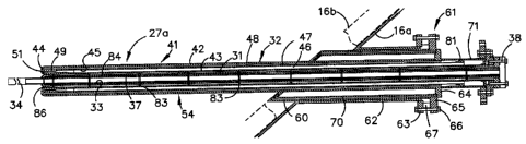
The construction of an injection lance for
carbonaceous material, identified as 27a, is illustrated
in Figures 2 to 4. As shown in these figures lance 27a
comprises a central core tube 31 through which to deliver
the solids material and an annular cooling jacket 32
CA 02575098 2007-01-25
W02006/010210
PCT/AU2005/001103
- 8 -
surrounding the central core tube 31 throughout a
substantial part of its length. Central core tube 31 is
formed of low carbon steel tubing 33 throughout most of
its length but its forward end is fitted with a
replaceable extension or nozzle tube 34 which projects as
a nozzle from the forward end of the cooling jacket 32.
Central core tube 31 is internally lined through
to the forward end part 34 with a ceramic lining 37 formed
by a series of cast ceramic tubes. The rear end of the
central core tube 31 is connected through a coupling 38 to
a coal delivery system through which particulate coal is
delivered in a pressurised fluidising gas carrier, for
example nitrogen.
Annular cooling jacket 32 comprises a long
hollow annular structure 41 comprised of outer and inner
tubes 42, 43 interconnected by a front end connector piece
44 and an elongate tubular structure 45 which is disposed
within the hollow annular structure 41 so as to divide the
interior of structure 41 into an inner elongate annular
water flow passage 46 and an outer elongate annular water
flow passage 47. Elongate tubular structure 45 is formed
by a long carbon steel tube 48 welded to a machined carbon
steel forward end piece 49 which fits within the forward
end connector 44 of the hollow tubular structure 41 to
form an annular end flow passage 51 which interconnects
the forward ends of the inner and outer water flow
. passages 46, 47. The rear end of annular cooling jacket
32 is provided with a water inlet 52 through which a flow
of cooling water can be directed into the inner annular
water flow passage 46 and a water outlet 53 from which
water is extracted from the outer annular passage 47 at
the rear end of the lance. Accordingly in use of the
lance cooling water flows forwardly down the lance through
the inner annular water flow passage 46 then outwardly and
back around the forward annular end passage 51 into the
CA 02575098 2007-01-25
WO 2006/010210
PCT/AU2005/001103
- 9 -
outer annular passage 47 through which it flows backwardly
along the lance and out through outlet 53. This ensures
that the coolest water is in heat transfer relationship
with the incoming solids material and enables effective
cooling of both the solids material being injected through
the central core of the lance as well as effective cooling
on the forward end and outer surfaces of the lance.
The outer surfaces of the tube 42 are machined
with a regular pattern of rectangular projecting bosses 54
each having an undercut or dove tail cross section so that
the bosses are of outwardly diverging formation and serve
as keying formations for solidification of slag on the
outer surfaces of the lance. Solidification of slag onto
the lance assists in minimising the temperature in the
metal components of the lance. It has been found in use
that slag freezing on the forward or tip end of the lance
serves as a base for formation of an extended pipe of
solid material serving as an extension of the lance which
further protects exposure of the metal components of the
lance to the severe operating conditions within the
vessel.
The lance is mounted in the wall of the
vessel 11 via a mounting structure 61 comprising a tubular
part 60 extended about the cooling jacket and having a
double walled construction so as to enclose an annular
space 70 between these walls. The tubular part 60 fits
within a tubular lance mounting bracket 62 welded to the
shell of vessel 11 so as to project upwardly and outwardly
from the vessel and provided at its upper end with an end
flange 63. Lance mounting structure 61 is connected to
the rear end of the outer tube 42 of annular cooling
jacket 32 via an annular ring 64 and it also includes an
annular mounting flange 65 which can be clamped to the
flange 63 at the end of mounting tube 62 via clamping
bolts 66. A split spacer ring 67 is fitted between the
CA 02575098 2007-01-25
WO 2006/010210
PCT/AU2005/001103
- 10 -
flanges 63, 65 to hold them apart when the clamping
bolts 66 are tightened. The arrangement is such that the
forward part of the outer sleeve 60 of structure 61 extend
through to the inside of the vessel wall. As seen in
Figure 2, the vessel wall at this location is formed by
the steel barrel shell 16a and an internal refractory
lining 16b and the forward end of sleeve 60 is inclined at
an angle to the central longitudinal axis of the lance so
as to be flush with the inner refractory surface.
The tubular part 60 of mounting structure 61 is
water cooled, cooling water being supplied to the interior
space 70 through a water inlet 68 and return through a
water outlet 69 at the rear end of the mounting sleeve.
The interior space 70 may be partitioned to provide an
extended cooling water flow passage within it.
A tubular housing 71 extending rearwardly from
the mounting ring 64 of mounting structure 61 houses the
rear end of the intermediate tube 48 of jacket 32 and the
rear end of the core tube 31 of the lance. Housing 71
carries the cooling water inlet 52 and outlet 53 for the
passage of cooling water to and from the lance cooling
jacket 32. A flexible annular connecting structure 81
connects the rear end of the intermediate tube 48 of the
water jacket with the housing tube 71 so as to separate
the inward and outward water flow passages within the
housing and to also permit relative longitudinal movement
between the inner and outer tubes and the intermediate
tube of the water jacket due to differential thermal
expansion and contraction in the components of the lance.
The rear end of tubular housing 71 provides a
mounting for the rear end of the inner tube 43 of the
annular cooling jacket.
CA 02575098 2007-01-25
WO 2006/010210
PCT/AU2005/001103
- 11 -
Core tube 31 is held in spaced apart
relationship within annular cooling jacket 32 by a series
of spacer collars 83 projecting outwardly from the central
core tube at longitudinally spaced locations along the
core tube to engage the inner periphery of the inner tube
of the annular cooling jacket so as to form an annular gas
flow passage 84 between the central core tube and the
annular cooling jacket. A purge gas inlet 85 is provided
at the rear end of the lance for admission of a purge gas
such as nitrogen to be admitted into the gas flow passage
84 to flow forwardly through the lance between the core
tube and the annular cooling jacket to exit the lance at
the forward end of the cooling jacket.
The central core tube is fitted with a bulbous
projection 86 in the region of the forward end of the
cooling jacket to provide a controlled nozzle opening
between the core tube and the water jacket to control the
purge gas flow rate. The spacer collars 83 are formed so
as to leave circumferentially spaced gaps between the
outer peripheries and the inner periphery of the cooling
jacket to allow for free flow of purge gas through the
annular purge gas flow passage 84. One of the end
collars 83 is located closely adjacent the bulbous
projection 86 so as to provide accurate location of that
projection within the forward end of the outer cooling
jacket so as to create the controlled annular gap for the
purge gas exit nozzle. The flow of purge gas is
maintained to ensure that slag can not penetrate the
forward end of the nozzle between the core tube and the
outer water jacket. If slag were to penetrate the lance in
this region it would immediately freeze because of the
water cooled outer jacket and the cold purge gas.
During operation of the lances slag will
accumulate on the outer surfaces of the lance and the
inner surface of the vessel. On shutdown the slag will
CA 02575098 2007-01-25
WO 2006/010210
PCT/AU2005/001103
- 12 -
solidify tending to bond the lance to the vessel. However
with the illustrated mounting arrangement this bond can
readily be broken to facilitate withdrawal of the lance.
This can be achieved by loosening the clamping bolts 66
sufficiently to enable withdrawal of the split spacer
ring 67. This then permits limited inward movement of the
lance mounting sleeve within the mounting tube 62 so that
the forward end of the mounting sleeve is moved inwardly
from the wall of the vessel to break any slag accretions.
This then allows the lance along with slag that has
solidified on the outer tube 42 to be readily withdrawn
through the enlarged opening provided for the tubular
mounting 60.
The hot ore injection lances may be of generally
similar construction to the coal injection lances.
However, as shown in Figures 5 and 6, the hot ore
lance 27b has an inner core tube formed as a thick walled
spun cast tube 31b with no liner. The tube 31b must be
made in sections which are joined by split joining
sleeves 91. Adjacent tubes can be aligned and connected
through the joining sleeves by stitch welding. The
forward end of the core tube 31b is provided with a
projection 86b to set .the size of the purge gas outlet
nozzle. Because of the thicker core nozzle tube in the
hot ore injection lance this projection is much smaller
than the more bulbous projection of the coal delivery
lance.
In a further modification, the hot ore injection
lance is provided with a water cooled flange 92 to stop
overheating of the housing tube 71b. This flange is
sandwiched between the water cooled end flange of the
lance housing and the flange on the end of the ore
injection system which may also be water cooled.
CA 02575098 2007-01-25
WO 2006/010210 PCT/AU2005/001103
- 13 -
The inner core tube of the hot ore injection
lance is held in spaced apart relationship within the
cooling jacket by a series of spacer collars projecting
outwardly from the central core tube in the same fashion
as in the coal lance construction. As in the coal lance,
the space between the inner core tube and the water jacket
provides an annular passage for flow of purge gas which
exits the lace at the forward end of the cooling jacket.
The outer mountings for the two kinds of
injection lance are identical so that both kinds of
injection lances can be inserted into a common design
housing.
Figure 7 provides a schematic illustration of a
solids injection lance 27c fitted into one of the tubular
lance mounting brackets 62 of vessel 11. The solids
injection lance 27c may be of the same general
construction as described in relation to Figures 2 through
6 above. The vessel wall 16 is lined internally with
water cooled refractory panels 100 and the lance 27c
extends into the vessel through an aperture in the panels
100. The lance 27c is modified such that the forward end
of its outer annular part 60 is fitted with a covering
annular disc 101 of refractory material to protect that
front face against exposure to excessive temperature
during start-up and lance replacement situations before
there is a build up of slag within the vessel. The
annular part 60 is extended within the vessel wall so that
the refractory disc 101 is flush with the inner face of
the water cooled panel 101 and it serves as a refractory
plug in the opening through that panel.