Language selection

Search

Patent 2575210 Summary

Third-party information liability

Some of the information on this Web page has been provided by external sources. The Government of Canada is not responsible for the accuracy, reliability or currency of the information supplied by external sources. Users wishing to rely upon this information should consult directly with the source of the information. Content provided by external sources is not subject to official languages, privacy and accessibility requirements.

Claims and Abstract availability

Any discrepancies in the text and image of the Claims and Abstract are due to differing posting times. Text of the Claims and Abstract are posted:

  • At the time the application is open to public inspection;
  • At the time of issue of the patent (grant).
(12) Patent Application: (11) CA 2575210
(54) English Title: WASTE PRESS DEVICE
(54) French Title: DISPOSITIF DE PRESSE DE DECHETS
Status: Deemed Abandoned and Beyond the Period of Reinstatement - Pending Response to Notice of Disregarded Communication
Bibliographic Data
(51) International Patent Classification (IPC):
  • B30B 9/30 (2006.01)
  • B65F 3/20 (2006.01)
(72) Inventors :
  • KAARLA, NIKLAS KARI ERIK (Finland)
  • LAUHIALA, MARKO TAPANI (Finland)
(73) Owners :
  • NIMATEK OY
(71) Applicants :
  • NIMATEK OY (Finland)
(74) Agent: BORDEN LADNER GERVAIS LLP
(74) Associate agent:
(45) Issued:
(86) PCT Filing Date: 2005-07-26
(87) Open to Public Inspection: 2006-02-02
Availability of licence: N/A
Dedicated to the Public: N/A
(25) Language of filing: English

Patent Cooperation Treaty (PCT): Yes
(86) PCT Filing Number: PCT/FI2005/000341
(87) International Publication Number: WO 2006010789
(85) National Entry: 2007-01-25

(30) Application Priority Data:
Application No. Country/Territory Date
20041034 (Finland) 2004-07-28

Abstracts

English Abstract


The invention relates to a waste press device consisting of a rotating drum
(8). The drum (8) contains an eccentric internal shaft (9), from which
striking rods (12) pass through a inlet hole (10) and through the drum, with
the drum end reciprocating axially during one revolution.


French Abstract

L'invention concerne un dispositif de presse de déchets pourvu d'un tambour rotatif (8). Ce tambour (8) présente un arbre interne excentrique (9), à partir duquel des tiges de frappe (12) s'étendent à travers un trou d'entrée (10) et à travers le tambour, l'extrémité du tambour effectuant un mouvement de va-et-vient axial au cours d'une révolution.

Claims

Note: Claims are shown in the official language in which they were submitted.

6
Claims
1. A waste press device comprising a rotating drum (8) having an internal
eccentric inner shaft (9), from which transfer rods (12) pass through a inlet
hole
(10) through the drum so that an end of the rod reciprocates axially during
one
revolution, characterised in that a rack of the device is arranged to move on
vertical rails (15).
2. A waste press device according to claim 1, characterised in that a power
source of the device is an electric motor (4) rotating both the drum (8) and
the
inner shaft (9) via a transmission.
3. A waste press device according to claim 1 or 2, characterised in that
shredders (18) are fixed to the device rack between the drum (8) and the
transfer rods (12).
4. A waste press device according to any of the preceding claims,
characterised in that a ramp (27) is provided in an extension of a feed ramp
(26) of the device for directing the goods through the waste press device
upwardly and further into a container.
5. A waste press device according to any of the preceding claims,
characterised in that said rack of the device is fixed to rolls (16) moving on
vertical rails.
6. A waste press device according to any of the preceding claims,
characterised in that transfer rods (12) comprises a moving member at the end
of each rod.

Description

Note: Descriptions are shown in the official language in which they were submitted.


CA 02575210 2007-01-25
PCT /F12005 /000341
Z4MAR 2=
Waste press device
This invention relates to a waste press device comprising a rotating drum
having an internal eccentric inner shaft, from which transfer rods pass
through
an inlet hole through the drum so that an end of the rod reciprocates axially
during one revolution.
Waste presses known per se comprise pendulum piston presses, screw
presses, axial-piston presses, baling presses, crushers, roller crushers and
hook shredders, Fl 41935, US 3 279 357 and GB 1 024 726, for instance,
disclose waste press devices known per se. These waste presses known per se
have the following shortcomings:
Pendulum piston press: a small-sized hopper opening, hydraulics; screw press:
slow because simultaneous crushing and pressing (inadequate force for both
operations); axial-piston press: an intermediate lid with low fault tolerance
(detachment under wear), discontinuous feed, hydraulics; bale press; intended
for small batches at one time, hydraulics, (relatively) high cost; crushers:
only
crushing, no pressing, materials required to be transferred to a separate
press;
roll crushers: only reduction of treated material particle size, treated
materials
stick to crusher teeth and return for other treatment cycles; so called hook
shredders: only shredding and crushing, materials required to be transferred
to
a separate press.
This invention has the purpose of overcoming the drawbacks mentioned above.
The waste press device of the invention is characterized by the rack of the
device is arranged to move on vertical rails.
The waste press device of the invention has the following advantages:
Low power consumption < 15kW per device: low operating costs. High material
handling capacity: time saving. Easy maintenance: no long delays for the
customer in case of malfunction. Straightforward mechanism: reliability.
Versatility: available in any size, with any width and height.
Low operating costs compared to hydraulic presses.
AMENDED SHEET (IPEA/FI)

CA 02575210 2007-01-25
FCt /Fl200 51 000341
24 MHR 10
2
Higher continuous feed speed: can handle larger amounts of materials in a
shorter amount of time compared to other presses.
No hydraulics: more environment-friendly and easier maintenance (also in the
winter).
It is able to reduce treated material to smaller particle size (e.g. cardboard
and
wood) if desired because of separate shredding rolls, in order to fit more
material better into containers, which means less frequent emptying of
containers. Slowly rotating mechanism: low operating costs and higher
reliability. The device rises over objects or materials that are too big:
higher fault
tolerance. Controlled by PLC logic: no need for physical monitoring of the
device.
The invention is explained below by means of an example and with reference to
the accompanying drawings, in which
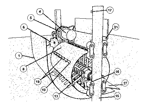
Figures 1-3 are axonometric views of the waste press from three different
directions.
The power supply is 400V/50Hz, fuse requirement: slow 32A. (1) over a current
wire cable to the device, from the plug contact to the electric cabie (3),
from
there to the electric motor (4) having a power in the range 40W-4OkW.
The electric motor is connected to a reduction gear (5) having an approximate
ratio of 1:7. On the reduction gear a sprocket wheel (6) and the power
transmission by means of a chain (7).
Chains drive two parts: the outer drum (8) and the inner shaft (9). The outer
drum has a number (n) of openings in rows (10) and the inner shaft comprises
transfer-rods (12) between flanges (11), the transfer-rods being "locked" by
locking shafts (13).
All the parts 4-13, 17,22 mentioned above are fixed to the same "rack", which
has vertical degree of freedom in the vector Z. Movement in the direction of
planes X and Y is limited by rails (15).
AMENDED SHEET (IPEA/FI)

CA 02575210 2007-01-25
PCT 1200 000341
3 ~ 4 MAR 20M
As the rack rises on the rails (15) along the rolls (i.e. controlled by rolls
(16)) up
to the set (e.g. limited) height, a limit-switch (17) short-circuits and
operation/drive is interrupted. The fed material can be directly reduced by
means of "shredders" (18) placed between the paths of the transfer-rods (the
shredders are e.g. rolls or disks).
The transfer-rods pass radially through the rod openings on the drum outwards
on the input-side (19) and inwards on the container (20) side. When the
transfer-rods have been completely retracted, the drum-wedge (21) (part of the
rack) mechanically removes all the small residues from the drum surface.
During the drive-cycle, the drum and inner shaft rotate at the same speed of
rotation. The device can be controlled via PLC logic (25). The materials are
fed
through a feeding opening arrive via the hopper ramp (26). A ramp (27) can be
placed to direct material upwards into the container.
The machine can be manufactured in a variety of sizes, for various purposes of
use by utilizing variations of the machine: municipal household waste
compactor, cardboard and paper compactor, wood or timber compactor,
expanded polystyrene and other packaging materials compactor, a small
household compactor, waste collection vehicle compactor, waste-bin pre-
compaction unit, restaurant food-waste bin compactor.
Examples of shredders: rollers, toothed shredders, fixed or stationary
shredders, axe-head blade shredders.
The entire rack can be shock absorbed by means of springs and shock
absorbers.
The shock absorption and springs can be adjustable.
The drum may be height-adjustable relative to the hopper ramp.
The feeding entrance to hopper ramp may be dispensed from the side or from
the top.
The hopper ramp may be straight, oblique, inclined, convex, concave or mobile.
AMENDED SHEET (IPEA/FI)

CA 02575210 2007-01-25
PCT IF12005/000341
2 4 r=f,~~ 2r~
4
A compression-ramp directly after the drum, may be straight, oblique,
inclined,
convex, concave or mobile.
The power transmission may consist of a chain, rope, pinion gear, worm gear or
any other drive member or mechanism. Power transmission may also be
implemented by hydraulic means. The power transmission may also be manual.
The shape of the transfer-rods may be: sharp, pointed, blunt, conical, chisel-
point, crosshead, toroidal head and may even have a moving member or a
mechanism at the end of the rod.
The compactor may comprise of n. amount of rods in n. amount of rows.
The same machine may comprise of two or more drums with their respective
transfer-rods.
The transfer-rods may be protected inside the drum with an elastic material.
The inner shaft can be protected e.g. by encapsulation or rubber mass lining.
All the parts and components can be coated e.g. with a suitable protective
resin.
The outer drum in itself may be flexible and radially adjustable.
The drum (8) does not necessarily move vertically on the rails (15), but
equally
may move horizontally: for instance, in a low space, the entire waste
compactor
may be turned upside down or 90 degrees on principle. The machine may also
operate with the drum (8) in stationary position and the side of the machine
separates from the drum if material gets between them and is pressed through.
The transfer-rods (12) in the drum (8), which form an elongated comb, may also
be replaced with a plate-like or slab-like element, which conveys or transfers
liquid or similar substances through the waste compactor better than transfer-
rods.
AMENDED SHEET (IPEA/FI)

CA 02575210 2007-01-25
PCT / F 1 2 0 0 5 / 0 0 0 3 4 1 2 4 MAR 1=
Since the rack consists of the drum (8) with a mobile unit and its components,
it
can be easily lifted upwards on the rails (15) and removed for service or
repair.
AMENDED SHEET (IPEA/FI)

Representative Drawing
A single figure which represents the drawing illustrating the invention.
Administrative Status

2024-08-01:As part of the Next Generation Patents (NGP) transition, the Canadian Patents Database (CPD) now contains a more detailed Event History, which replicates the Event Log of our new back-office solution.

Please note that "Inactive:" events refers to events no longer in use in our new back-office solution.

For a clearer understanding of the status of the application/patent presented on this page, the site Disclaimer , as well as the definitions for Patent , Event History , Maintenance Fee  and Payment History  should be consulted.

Event History

Description Date
Application Not Reinstated by Deadline 2009-07-27
Time Limit for Reversal Expired 2009-07-27
Deemed Abandoned - Failure to Respond to Maintenance Fee Notice 2008-07-28
Letter Sent 2007-05-23
Inactive: Cover page published 2007-04-11
Inactive: Single transfer 2007-04-03
Inactive: Courtesy letter - Evidence 2007-04-03
Inactive: Notice - National entry - No RFE 2007-03-28
Application Received - PCT 2007-02-22
National Entry Requirements Determined Compliant 2007-01-25
Application Published (Open to Public Inspection) 2006-02-02

Abandonment History

Abandonment Date Reason Reinstatement Date
2008-07-28

Maintenance Fee

The last payment was received on 2007-07-05

Note : If the full payment has not been received on or before the date indicated, a further fee may be required which may be one of the following

  • the reinstatement fee;
  • the late payment fee; or
  • additional fee to reverse deemed expiry.

Please refer to the CIPO Patent Fees web page to see all current fee amounts.

Fee History

Fee Type Anniversary Year Due Date Paid Date
Basic national fee - standard 2007-01-25
Registration of a document 2007-04-03
MF (application, 2nd anniv.) - standard 02 2007-07-26 2007-07-05
Owners on Record

Note: Records showing the ownership history in alphabetical order.

Current Owners on Record
NIMATEK OY
Past Owners on Record
MARKO TAPANI LAUHIALA
NIKLAS KARI ERIK KAARLA
Past Owners that do not appear in the "Owners on Record" listing will appear in other documentation within the application.
Documents

To view selected files, please enter reCAPTCHA code :


To view images, click a link in the Document Description column. To download the documents, select one or more checkboxes in the first column and then click the "Download Selected in PDF format (Zip Archive)" or the "Download Selected as Single PDF" button.

List of published and non-published patent-specific documents on the CPD .

If you have any difficulty accessing content, you can call the Client Service Centre at 1-866-997-1936 or send them an e-mail at CIPO Client Service Centre.


Document
Description 
Date
(yyyy-mm-dd) 
Number of pages   Size of Image (KB) 
Abstract 2007-01-25 1 123
Drawings 2007-01-25 2 267
Description 2007-01-25 5 179
Representative drawing 2007-01-25 1 97
Claims 2007-01-25 1 32
Cover Page 2007-04-11 1 117
Reminder of maintenance fee due 2007-03-28 1 110
Notice of National Entry 2007-03-28 1 192
Courtesy - Certificate of registration (related document(s)) 2007-05-23 1 107
Courtesy - Abandonment Letter (Maintenance Fee) 2008-09-22 1 172
PCT 2007-01-25 15 473
Correspondence 2007-03-28 1 26
Fees 2007-07-05 1 33