Note: Descriptions are shown in the official language in which they were submitted.
CA 02575324 2007-01-26
WO 2006/015117 PCT/US2005/026779
AN APPARATUS AND METHOD FOR HOLDING AND PROTECTING
DRUG DELIVERY DEVICES
CROSS-REFERENCE TO RELATED APPLICATIONS
[0001] This application claims priority to co-pending U.S. Provisional
Application No.
60/591,677, filed on July 28, 2004, which is entirely incorporated herein by
reference.
FIELD OF THE INVENTION
[0002] This invention relates to packaging, and more specifically to a two-
piece
apparatus that houses one or more drug delivery devices on an internal slide
card within an
outer shell. This apparatus may have one or more intemal or extemal locks that
prevent the slide
card from being pulled out without triggering a related lock release.
BACKGROUND OF THE INVENTION
[0003] Conventional pharmaceutical packaging has shortcomings with regard to
injectables, which create problems for both the manufacturer and end user. For
example, there
is known to distribute syringes, vials, and parts thereof in packaging that
incorporate foam or
plastic elements to protect the product. Such conventional packaging normally
holds the
product in a vertical position. Where conventional packaging holds the product
in a horizontal
position, the products are typically stacked on top of each other. There is
also known to
distribute syringes, vials, and parts thereof loose -- or loose, but
individually wrapped -- in
conventional boxes without any means for holding or protecting the products.
[0004] The conventional manufacturer that incorporates foam or plastic
elements in its
packaging to protect the product carries an increased inventory and employs a
more
complicated manufacturing system to produce its packaging. Further, the
conventional
manufacturer typically produces one kind of package to be filled by automated
means and
CA 02575324 2007-01-26
WO 2006/015117 PCT/US2005/026779
another kind to be filled by hand, which also increases inventory and the
number of product
lines.
[0005] Conventional -manufacturers of injectable holding packaging typically
do not
provide a child-resistant feature to prevent unauthorized access, or a
stopping feature to
prevent accidental spillage. Where these features do exist, they exist at the
expense of easy
access for the end user with limited dexterity. Neither does the known
injectable packaging
provide ample space to place appropriately sized graphics, such as dose
compliance
instructions and warnings, for the end user with limited sight.
[0006] In addition, conventional manufacturers pack injectables tightly and in
the most
efficient manner possible -- from the perspective of shipping cost savings --
but, again, at the
expense of the end user who has limited physical mobility, such as an end user
with arthritis of
the fingers. Also conventional manufacturers are known to distribute only
wholly-assembled
syringes together, parts of syringes together, or vials together, but not
whole syringes or parts
or vials mixed together. This convention requires the end user to create and
maintain an
inventory of injectables to fill their individual needs.
[0007] End users are familiar with the disposal problems created by the use of
injectables. Typically, spent vials, needles, syringes, barrels, and other
injectables or parts
thereof must be sealed or otherwise protected in order to be disposed of
safely. While it is
known to dispose of injectables in a separate device, such as a sealable
plastic container,
there remains a need for an injectable packaging that also serves as a safe
means of disposal.
[0008] It is apparent from a survey of the pharmaceutical arts that there
exists a need
for an apparatus that holds and protects all types of drug delivery devices
and parts thereof,
allows for improved manufacturing processes, includes child-resistant and
spill-prevention
features, stores a variety of objects in response to the end users' needs, is
fitted for easy
access by the end user who has limited dexterity, has sufficient area to
receive graphics, and
provides a means for safe disposal.
-2-
CA 02575324 2007-01-26
WO 2006/015117 PCT/US2005/026779
SUMMARY OF THE INVENTION
[0009] Generally speaking, the present invention fulfills the needs identified
above by
providing packaging embodiments comprising an outer sleeve and an inner slide
card retained
within the outer sleeve and with embodiments that releaseably lock the inner
slide card within the
outer sleeve. In lockable embodiments, the outer sleeve includes at least one
panel with an inner
slide card means for locking, an inner slide card means for releasing, and an
optional inner
slide card means for stopping. The inner slide card includes a tray and at
least one panel
configured to cooperatively engage the outer sleeve means for locking, means
for releasing,
and optional means for stopping.
[00010] In exemplary embodiments the inner slide card means for locking
include
extension panels or tabs integral to the inner card or, optionally,
attachments extending
therefrom, configured to releasably engage the outer sleeve. Also the inner
card means for
releasing includes a catch and a release on an outer sleeve panel, or an
attachment
extending therefrom, configured to releasably engage said means for locking.
The inner
slide card means for locking or retaining comprises inner card and outer
sleeve extension
panels or tabs configured to engage, or attachments or catches associated with
the card and
sleeve that are configured to engage. Thus the present invention provides an
optional child-
resistant feature.
[00011] In exemplary embodiments, the inner card means for stopping comprises
inner
card and outer sleeve extension panels or tabs configured to engage, or
attachments or
catches associated with the card and sleeve that are configured to engage.
Thus the present
invention provides an optional spill-resistant feature to prevent the user
from pulling the inner
card completely away from the outer sleeve, but which can be opened and closed
numerous
times to access the drug delivery devices.
[00012] Alternative embodiments include an apparatus and method for holding
and
storing drug delivery devices by providing an inner tray configuration that,
by way of example
and not limitation, protects a plunger from inadvertent activation; shields a
needle from
inadvertent exposure; allows easy access to a drug-filled container for
removal and
-3-
CA 02575324 2007-01-26
WO 2006/015117 PCT/US2005/026779
replacement; and collects and stores the spent devices. Accordingly,
embodiments of the
present invention provide an apparatus and system that is able to safely ship
drug delivery
devices for transepidermal, oral, and hypodermic administration, including pre-
filled syringes,
needles, vials, ampoules, protective shields, and accessories, safely store
the unused devices,
and safely store the used devices until all can be safely disposed as a unit.
[00013] Alternative embodiments include an apparatus and method for providing
compliance directions or information directed to therapy management. In one
embodiment,
indicia such as, but not limited to, time of day, days of the week, numerical
sequence, or
dosage amounts are positioned adjacent to the devices. In another embodiment,
compliance
information or general information related to the medication or therapy is
positioned on or with
the inner slide card or outer sleeve in a manner easily visible by the user.
[00014] Further embodiments include an apparatus for use with a high volume
pick-and-
pack manufacturing process. The same embodiments provide an apparatus for use
with a
hand pick-and-pack manufacturing process. Another embodiment includes an
apparatus and
method for protecting and storing spent drug delivery devices within a secure
container until
they can be disposed of in a controlled fashion.
[00015] Embodiments according to this invention offer at least the following
advantages: lightness in weight, resistance to tampering, child-resistance,
ease of access,
excellent durability, ease of assembly, device protection, ease of storage,
ease of disposal,
the ability to present devices of different and unusual shapes, and excellent
economy.
[00016] It is also contemplated that the present invention is not limited to
pharmaceutical-related goods, but is applicable to a plethora of delicate,
sensitive, or unique
portable articles. Small electronic components, jewelry, foods, expensive and
precious
goods, and any other item which requires a safe, stable, and portable
environment in which to
be shipped and stored may find an application with the present invention.
Other advantages
of the present invention will be apparent from the following description, the
accompanying
drawings, and the appended claims.
-4-
CA 02575324 2007-01-26
WO 2006/015117 PCT/US2005/026779
BRIEF DESCRIPTION OF THE DRAWINGS
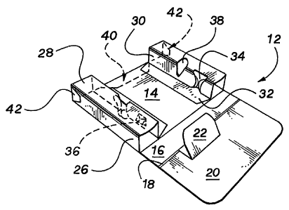
[00017] FIG. 1 is a plan view of an embodiment of a combined slide card and
tray blank,
according to the present invention.
[00018] FIG. 2 is a perspective view of the completely constructed blank of
FIG. 1.
[00019] FIG. 3 is a perspective view of an alternative embodiment of a slide
card and
tray, according to the present invention.
[00020] FIG. 4 is a plan view of an embodiment of an outer sleeve blank,
according to the
present invention.
[00021] FIG. 5 is a perspective view of the completely constructed blank of
FIG. 4.
DETAILED DESCRIPTION OF THE INVENTION
[00022] As required, detailed embodiments of the present invention are
disclosed herein.
It will be understood that the disclosed embodiments are merely exemplary of
the invention
that may be embodied in various and alternative forms. The figures are not
necessarily to
scale, and some features may be exaggerated or minimized to show details of
particular
components. In other instances, well-known materials or methods have not been
described in
detail in order to avoid obscuring the present invention. Therefore, specific
structural and
functional details disclosed herein are not to be interpreted as limiting, but
as a basis for the
claims and for teaching one skilled in the art to variously employ the present
invention.
[00023] Referring now to the drawings, wherein like numerals represent like
features
throughout, there are illustrated embodiments of the present invention.
Turning first to FIG. 1
and FIG. 2, there is shown an internal slide card blank 10 configured to form
an inner tray 12
for holding articles such as drug delivery devices. Herein, the term "drug
delivery devices,"
whether in the singular or plural, is used broadly to refer to all apparatus
and parts thereof
used in conjunction with transferring solids, fluids, or gases into or out of
a body. By way of
example and not limitation, a drug delivery device may be in the form of an
injectable device
comprising a needle, plunger, and cap used by a medical professional to treat
a patient with a
-5-
CA 02575324 2007-01-26
WO 2006/015117 PCT/US2005/026779
pharmaceutical drug in liquid form. The same term is applicable herein to
refer to all parts of
the device as well as the vial(s) used to hold or receive the drug. For
purposes of teaching
and not limitation, the illustrated embodiments are directed to packaging for
articles such as a
drug delivery device in the form of an injectable device.
[00024] As best shown in FIG. 1, the illustrated blank 10 includes a base
panel 14, spine
panel 16, and top panels 18, 20. The top panel 20 comprises an integral spine
support panel
22, formed by cuts 23 and fold lines 24. Blank 10 further includes extension
panels 25.
[00025] An extension panel 25 comprises an outside sidewall panel 26, top
panel 28,
inside sidewall panel 30, and securing panel 32. Further, panel 25 comprises a
plunger-
receiving slot 34, formed by cuts 23 and fold lines 24, and a needle-receiving
aperture 36, 38.
Alternative aperture designs are shown to illustrate a means for securing
syringe ends with or
without a protective cap. As understood by one skilled in the art, in certain
embodiments the
aperture 36 may be formed by cuts 23 in the form of an "X" while in other
embodiments the
aperture 38 may be formed by cuts 23 that create a void.
[00026] Blank 10 further includes locking tab 40 and stopping tabs 42. As
described in
detail below, locking tab 40 cooperatively engages with another element to
create a child-
resistant feature. Also as described below, stopping tabs 42 cooperatively
engage with
another element to create a pull-out stop that also functions as a spill-
resistant feature. With
the explanation below, one skilled in the art will understand that the child-
resistance feature
and stopping feature can both be created, alternatively, with either tabs 40,
42 individually or
together. Accordingly, both tabs 40, 42 are a means for locking and a means
for stopping.
[00027] With respect to assembly, blank 10 is folded and connected, using
conventional
techniques, to create the combined internal slide card and inner tray 12, best
shown in FIG. 2.
One sequence of folding and connecting the blank 10 to form the tray 12,
described merely for
the purpose of teaching and not limitation, with reference to the visible side
of the illustrated
blank 10 as the face and the opposite side as the back, is as follows: The
face of top panel 20
is folded and affixed to the face of top panel 18 so that the face of spine
support panel 22
overlaps the face of spine panel 16. The face of each of the outside wall
panels 26, top panel
-6-
CA 02575324 2007-01-26
WO 2006/015117 PCT/US2005/026779
28, and inside wall panel 30 are folded toward each other to form an open-end
channel. With
the faces of panels 26, 28, and 30 orientated toward each other, the face of
securing panel 32
is attached to the face of base panel 14. In addition, as described below,
locking tab 40 will be
folded so that the back of locking tab 40 is orientated toward the back of
base panel 14.
Similarly, stopping tabs 42 will be folded so that the backs of stopping tabs
42 are orientated
toward the backs of the respectively adjacent outside sidewall panels 26.
[00028] After assembly, the inner tray 12 is configured to receive and store
an injectable
device (not shown). In the illustrated embodiment of FIG. 2, a plunger handle
may be received
and secured by the plunger-receiving slot 34 while a needle may be received
and secured by
the needle-receiving apertures 36, 38. By way of illustration and not
limitation, the receiving
slot 34 and cutouts 36, 38 include features for securing the injectables.
Here, the receiving
slot 34 is shaped as an hourglass because this shape holds a plunger handle in
a particular
position while allowing easy access. Those skilled in the art will understand
that receiving slot
34, as a means for securing an injectable, may be configured in various
shapes, depending on
the injectable and ease or complexity of access desired. For example, a
receiving slot 34 in
the shape of a "J," "L," "G," and "H" all provide varying levels of security
and access for the
injectable. In addition, the means for securing may comprise inserts of
different materials,
such as plastic or rubber yokes, to further secure or removably lock the
injectables in position.
[00029] Similarly, here apertures 36, 38 are shaped as an "X" and as an oval
because
these shapes can hold a bare needle, capped needle, or the neck of a vial in a
particular
position while allowing easy access. Those skilled in the art will understand
that apertures 36,
38, as a means for securing an injectable, may be configured in various shapes
depending on
the injectable and ease or complexity of access desired. For example, an
injectable
comprising a plunger handle, barrel, and needle may be stored by placing the
plunger handle
in receiving slot 34 and the needle in the aperture 36, 38 located in the
opposite inside sidewall
panel 30, with the barrel spanning the space in between. In this manner the
plunger of a pre-
filled injectable is protected from inadvertent pressure, and the user is
protected from
inadvertent contact with the needle.
-7-
CA 02575324 2007-01-26
WO 2006/015117 PCT/US2005/026779
[00030] FIG. 3 shows an altemative embodiment of an inner card 100 for
receiving and
holding injectables, according to the present invention. The illustrated inner
card 100 includes
an internal slide 102 that comprises a base panel 104, spine panel 106, and
top panel 108.
Here, rather than using paperboard to monolithically form the inner tray and
slide card as
described above, the inner tray 110 is therrimoformed separately and then
affixed to the slide
card 102. The inner tray 110 comprises a means for securing and holding
injectables, such as
the plunger 112 in the plunger-receiving recess 114 and the barrel 116 in the
barrel-receiving
recess 118. The recesses 114, 118 may be configured to lock in or otherwise
secure the
injectable by including a means for resisting removal of the injectable, such
as fold-over
locking flaps, indentions, or inserts. Accordingly, a means for holding and
storing a drug
delivery device includes a tray constructed in a variety of ways.
[00031] Here the inner tray 110 is also configured to allow for easy access to
the
injectables. By way of illustration and not limitation the injectables are
arranged alternately so
that the end user, who may have limited physical mobility such as that
resulting from arthritis,
can retrieve one injectable without affecting another. As illustrated,
purposefully orientating the
widest portion of the injectable, in this example the finger guard 120, to
take the most space to
provide the greatest accessibility is a desirable feature of this embodiment.
Such horizontal
orientating also provides easy viewing of the products so the user may easily
distinguish
between them. Further, such orientating provides ample area to receive
graphics. Patient and
healthcare provider information, such as dose compliance, can be made easily
visible to the
user.
[00032] The embodiment of FIG. 3 further includes tab 122 which may function
as a
means for locking and/or as a means for stopping, like the locking tab 40 and
stopping tab 42
described herein.
[00033] Turning now to FIGS. 4 and 5, there is shown an outer sleeve 200, for
receiving
an inner card 12, 100 and the related outer sleeve blank 202. As best shown in
FIG. 4, the
illustrated blank 202 includes side panels 204, 206, 208, spine panels 210,
end panels 216,
218, and extension panels 220.
-8-
CA 02575324 2007-01-26
WO 2006/015117 PCT/US2005/026779
[00034] With regard to assembly, the blank 202 is folded and connected, using
conventional techniques, to create the outer sleeve 200, best shown in FIG. 5
as a slip case.
One sequence of folding and connecting the blank 202 is as follows, with
reference to the
visible side of the illustrated blank 202 as the face and the opposite side as
the back: Side
panel 204 is folded along fold lines 24 under the side panels 206, 208 and
positioned over
panel 208 so that the back of panel 204 may be affixed to the face of panel
208. In this
embodiment, panel 204 is overlayed and affixed to panel 208 so that the cutout
222 of panel
208 surrounds the release button 224. In other words, the release button 224
is unobstructed
by panel 208.
[00035] Tabs 226 are folded inwardly to create a closed endwall, such that the
backs of
tabs 226 are orientated toward the interior case created by the side panels
204, 206 and spine
panels 210. End panels 216, 218 are then folded inwardly so that the face of
tabs 226 may be
affixed to the back of panel 216 and the face of panel 216 may be affixed to
the back of panel
218, to complete the closed endwall.
[00036] In addition, extension panels 220 are folded inwardly so that the back
of panels
220 may be affixed to the backs of respectively adjacent side panels 206, 208.
Similarly,
extension tabs 228 are folded inwardly so that the backs of tab 228 may be
affixed to the
respectively adjacent spine panels 210. The folding of panels 220 form finger-
access areas at
the cutouts 230.
[00037] Generally speaking, injectables are placed within inner tray 12, 100
and then the
inner tray 12, 100 is inserted into outer sleeve 200. The apparatus holds and
protects the
injectables until they are retrieved for use. In practice, and with reference
to FIGS. 1 and 2,
injectables are placed within the inner tray 12 and then several panels or
tabs are folded
before the internal card and inner tray 12 is inserted into the outer sleeve
200. For purposes of
teaching and not limitation, the following folding sequence is described. Top
panel 20 is folded
so as to cover the injectables and orientate the spine support panel 22 so as
to provide
support for the spine 16. In the illustrated embodiment, the back of top panel
20 is now
adjacent to the injectables and panel 22 is now substantially parallel to
panel 16. Further,
-9-
CA 02575324 2007-01-26
WO 2006/015117 PCT/US2005/026779
locking tab 40 is folded outwardly, so that the back of tab 40 is close to or
touching the back of
base panel 14 and stopping tabs 42 are folded outwardly so that the backs of
tabs 42 are close
to or touching the back of the respectively adjacent sidewall panel 26.
[00038] With the internal card and inner tray 12 loaded with injectables and
folded as
described immediately above, the tray 12 is inserted, starting with the edge
comprising the
tabs 40, 42 and with tab 40 receivingly aligned with the catch formed by
cutout 222 and
release button 224, into the void of outer sleeve 200. The internal card and
inner tray 12 is
fully inserted into the outer sleeve 200, to a fully closed position. As
understood by those
skilled in the art, the spring tension created by the outwardly folded tabs
40, 42 causes the
leading edge of the tabs 40, 42 to press against the interior side of the
panels 204, 208, 210.
The position of the tab 40 provides a locking feature and the tab(s) 42
provide a stopping
feature. For purposes of teaching and not limitation, the locking feature is
described with
regard to tab 40, and the stopping feature is described with regard to tab
42.. It will be
understood that either tabs 40 or 42 could interchangeably perform either the
locking or
stopping features.
[00039] In this illustration the locking feature includes the catch formed by
the cutout 222,
the release button 224 and cooperatively interlocking tab 40. The spring
tension created by
the compressed tab 40 causes the leading edge of tab 40 to engage the internal
edge 240 of
the panel 208. With the tab 40 and leading edge 240 engaged, the inner tray 12
is locked and
cannot be opened. This means for locking creates a child-resistant feature. To
unlock the
child-resistant feature of this embodiment and thereby open the tray 12, the
user depresses
the release button 224, created by the cut 23, which in turn depresses the tab
40 to disengage
the leading edge of the tab 40 from the internal edge 240. It will be
understood that another
means for locking may be created by placing one or more release buttons in
panel(s) 210 to
releaseably engage tab(s) 42.
[00040] After releasing the optional locking feature, the inner card 12 may be
pulled out,
until the stopping tabs 42 engage the extension tabs 228, to a fully open
position. As will be
understood by those skilled in the art, the spring tension created by the
compressed tabs 42
-10-
CA 02575324 2007-01-26
WO 2006/015117 PCT/US2005/026779
causes the leading edge of the tabs 42 to engage the tabs 228. Once engaged,
the tray 12
cannot be further removed from the outer sleeve 200 but may be reinserted to a
fully closed
position if desired. In this manner, tabs 42, 228 act as a stopping device to
prevent inner card
12 from being pulled completely out of outer sleeve 100. It will be understood
that another
means for stopping can be created by allowing tab 40 to engage extension tabs
220.
[00041] The user may open and close the apparatus by withdrawing and replacing
the
inner tray 12 within the outer sleeve 200 as often as desired. In the fully
open position, the
user may fold back the top panel 20 to access an injectable. After accessing
the desired
injectable, the user replaces the top panel 20 and reinserts the inner tray 12
within the outer
sleeve 200 for future use.
[00042] Alternatively, an embodiment designed to be disposed of, together with
used
injectables, may be placed within a red plastic bag (not shown but provided
with the
embodiment) thereby giving notice of the contents. By way of illustration and
not limitation,
additional means for protecting and sealing an embodiment to be disposed of,
together with
used injectables, include sealable bags, a self-sealing outer sleeve, a
sealable outer sleeve
large enough to receive the inner tray 12 and outer sleeve 200. Similarly,
taping the inner tray
12 within the outer sleeve 200 with red tape giving notice of the contents is
a means for
protecting and sealing.
[00043] With regard to the materials of construction, the illustrated
embodiments
comprise paperboard as a substrate for blanks 10, 202, which is typically
constructed from a
sheet of bleached sulphate, solid unbleached sulphate, or clay-coated
newsback.
Compositionally the paperboard coating is a fluidized blend of materials, such
as coating clay,
calcium carbonate, and/or titanium dioxide, with starch or adhesive that is
smoothly applied to
the traveling surface. Successive densification and polishing finish the
mineral-coated surface
to a superior, graphic-print surface. Other embodiments may comprise vacuum-
formed plastic
or paper, press-formed paperboard, cardboard, or combinations thereof.
[00044] It must be emphasized that the law does not require and it is
economically
prohibitive to illustrate and teach every possible embodiment of the present
claims. Hence, the
-11-
CA 02575324 2007-01-26
WO 2006/015117 PCT/US2005/026779
above-described embodiments are merely exemplary illustrations of
implementations set forth
for a clear understanding of the principles of the invention. Variations,
modifications, and
combinations may be made to the above-described embodiments without departing
from the
scope of the claims. All such variations, modifications, and combinations are
included herein
by the scope of this disclosure and the following claims.
-12-