Note: Descriptions are shown in the official language in which they were submitted.
CA 02575444 2007-01-25
WO 2006/023472 PCT/US2005/029061
DOORFRAME
FIELD OF THE INVENTION
This invention generally relates to a doorframe, and more specially, relates
to a
doorframe that can be installed into a wall-body as an assembly after the wall-
body has
been built.
BACKGROUND OF THE INVENTION
In constructing residential and commercial buildings, a doorframe is usually
installed
into a doorway on a wall-body after the wall-body is completely built.
Traditionally, the
width of a doorframe is fixed and cannot be adjusted. Therefore, to fit wall-
bodies having
different widths, some doorframes need to be specifically ordered or
manufactured in
advance for these wall-bodies after designs of the buildings have been
completed. The
situation would be more troublesome when the widths of some wall-bodies in a
building
are determined or adjusted during construction. In this situation, some
doorframes have
to be specially ordered or manufactured for the wall-bodies during
construction or after
completion of the wall-bodies, thus increasing manufacturing complexity and
manufacturing cost and delaying construction progress.
In addition, traditional doorframes have shortcomings in some design aspects,
which
cause manufacturing complexity and may have some negatively effects on the
artistic
appearance and on the use safety of the doorframes.
CA 02575444 2007-01-25
WO 2006/023472 PCT/US2005/029061
SUMMARY OF THE INVENTION
One objective of the invention is to provide a doorframe as an assembly with
its width
being able to be adjusted to fit wall-bodies having different thicknesses.
Another objective of the invention is to improve the structure of doorframes
to simplify
the manufacturing and installation process and improving the artistic
appearance and their
use safety of the doorframes.
According to the present invention, a doorframe assembly (100) for being
mounted
into a wall-body (10) comprises a left doorframe post (102), a right doorframe
post (104)
and a transverse doorframe post (106). Each of the three doorFrame posts (102,
104,106) further comprises a doorframe post front portion (202) having an L-
shaped
transverse section; a doorframe post rear portion (204) having an L-shaped
transverse
section; a doorframe middle portion (207) having a T-shaped transverse
section; wherein
the wall-body (10) has a doorway (12) defined by a front wall-body (212), a
rear wall-body
(214) and a side wall-body (216); wherein the doorframe post front portion
(202) is
mounted around the corner at the joint section of the front wall-body (212)
and the side
wall-body (216); wherein the doorframe post rear portion (204) is mounted
around the
corner at the joint section of the rear wall-body (212) and the side wall-body
(216); and
wherein the doorFrame post middle portion (205) is installed between the
doorframe post
front portion (202) and the doorframe post rear portion (206).
In comparison with the prior art, the doorframe assembly (100) can be adjusted
fitting
to wall-bodies having different thicknesses.
2
CA 02575444 2007-01-25
WO 2006/023472 PCT/US2005/029061
BRIEF DESCRIPTION OF THE DRAWINGS
Those skilled in the art can clearly understand the above-mentioned
objectives, the
technical problems to be solved, the technical features and other aspects of
the invention
through the following specific embodiments in combination with the following
accompanying drawings:
Figure 1A is a perspective view of a wall-body 10 having a doorway 12;
Figure 1 B a perspective view of a doorframe 100, which is installed in the
doorway 12
of the wall-body 10 according to the present invention;
Figure 1 C is a front view of the doorframe 100 and the door 108 installed
within the
doorframe 100 to show a left doorframe post 102, a right doorframe post 104
and a
transverse doorframe post 106 according to the present invention;
Figure 2A is a section view along section line A-A in Figure 1 C;
Figure 2B is a section view along section along line B-B in Figure 1C;
Figure 3A shows the transverse section view of a doorframe section 302 in
prior art;
Figure 3B shows the transverse section view of doorframe post front portion
202 or
doorframe post rear portion 204 of a doorFrame post 102, 104 or 106;
Figure 4A, 4B, 4C and 4D are the assembling diagrams for the doorframe
according
to the present invention;
Figure 5 shows a perspective view to show the door 108 and the doorframe 100
to be
installed in the doorway of the wall-body in accordance with the invention;
and
Figures 6A to 6H show process for gluing fire-resistant decorative laminate
(or high
pressure decorative laminate) onto the doorframe according to the present
invention.
3
CA 02575444 2007-01-25
WO 2006/023472 PCT/US2005/029061
DETAILED DESCRIPTION
Figure 1A is a perspective view of wall-body 10. The wall-body 10, with a
doorway
12 on it, has a front wall-body 212, a rear wall-body 214 and a side wall-body
216. The
rear wall-body 214 is not shown in Figure 1A because it is behind the front
wall-body 212
thus being shielded by the front wall-body 212. The rear wall-body 214 is
clearly shown
in Figures 2A and 2B.
Figure 1 B is a perspective view of the doorframe 100 that is installed into
the doorway
12 of the wall-body 10 according to the present invention. As shown in Figure
1 B, the
doorframe 100 comprises a left doorframe post 102, a right doorframe post 104
and a
transverse doorframe post 106 that are installed into the doorway 12.
Figure 1C is a front view of the doorframe 100, within which a door 108 is
installed, in
accordance with the present invention. As'shown in Figure 1C, the door 108 is
movably
installed within the left doorframe post 102, the right doorframe 104 and the
transverse
doorframe post 106. The door 108 can be movably mounted on the left doorframe
post
102 by using two or more hinges (not shown in Figure 1 C). A handle 103 is
mounted on
the door 108. Therefore, by using the handle 103, the door 108 can be rotated
inward to
be closed or rotated outward to be opened around the left doorframe post 102.
;
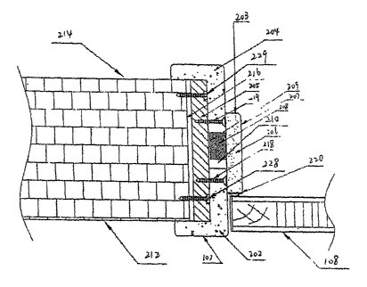
Figure 2A is a section view along section line A-A in Figure 1 C. At the left
hand of
Figure 2A is a section view of the left doorframe post 102 along section A-A
line, at the
right hand of Figure 2A is a section view of the right doorframe post 104
along section line
A-A, and in the middle of Figure 2A is a section view of the door 108 along
section line
4
CA 02575444 2007-01-25
WO 2006/023472 PCT/US2005/029061
A-A.
Figure 2B is a section view of the transverse doorFrame post 106 and the door
108
along section line B-B in Figure 1 C.
As can be seen from Figures 2A and 2B, the section view of the left doorframe
post
102, the right doorFrame post 104 and transverse doorframe post 106 are the
same (or
symmetrical) in structure. For the simplicity of describing the present
invention, each of
the three doorframe posts (102, 104 and 106) can be generally referred to as a
doorFrame
post. Therefore, in this specification, same components in all three doorframe
posts (102,
104 and 106) will use the same reference numbers, and the description of a
component in
any one of the three doorframe posts (102, 104 or 106) is deemed as the
description to
the corresponding components in the other two doorframe posts.
As shown in Figures 2A and 2B, a cushiQn plate 205 is mounted on the side wall-
body
216 by using a pair of screws 228 and 229. The cushion plate 205 has two
functions.
One function is used as an installation base for a doorframe assembly so as to
control
levelness and verticality and to control dimensional accuracy in installing
the doorFrame
assembly. The other function is used for mounting individual components of a
doorframe.
Because the cushion plate 205 is made of woods or of the materials having
properties
similar to woods, it can be easily cut to fit the thickness of side wall- body
216.
The left doorframe post 102 (the right doorframe post 104 or the transverse
doorframe post 106) comprises a doorframe post front portion 202, a doorframe
post rear
portion 204 and a doorframe post middle portion 207. Each of front portion 202
and rear
portion 204 has an L-shaped transverse section while the doorFrame post middle
portion
CA 02575444 2007-01-25
WO 2006/023472 PCT/US2005/029061
207 has a T-shaped transverse section. In installation, the doorframe post
front portion
202 is amounted at the joint corner of the front wall-body 212 and the side
wall-body 216,
and the doorframe post rear portion 204 is mounted at the joint corner of rear
wall-body
214 and the side wall-body 216. The cushion plate 205 is disposed between the
side
wafl-body 216 and the back sides of the doorframe post front portion 202 and
the
doorframe post rear portion 204.
As shown in Figures 2A and 2B, the doorframe post front portion 202 and the
doorframe rear portion 204 are mounted on the cushion plate 205 by a pair of
screws 218
and 219, respectively. The cushion plate 205 is in turn mounted on the side
wall-body
216 by a pair of crews 228 and 229. If the side wall-body 206 is thicker, more
crews
may be used to mount the doorframe post front portion 202, the doorframe rear
portion
204, and the cushion plate 205.
As shown in Figures 2A and 2B, when the doorframe post front portion 202 and
the
doorframe post rear portion 204 are mounted on the side wall-body 216, there
formed a
gap 209 between the doorframe post front portion 202 and the doorframe post
rear portion
204.
The transverse section of the doorframe post middle portion 207 is in a T-
shape.
The length of upper half part 206 of the doorframe post middle portion 207,
namely the
horizontal part of the T-shape, is longer than that of the gap 209. The length
of the lower
half part 208 of the doorframe post middle portion 207, namely the vertical
part of the T
shape, is shorter than that of the gap 209. Thus, when the lower half part
portion 208 of
the doorframe post middle portion is inserted into gap 209, the upper half
part 207 of the
6
CA 02575444 2007-01-25
WO 2006/023472 PCT/US2005/029061
T-shape can tightly contact the surface of the doorframe post front portion
202 and the
doorframe post rear portion 204, thus covering the holes formed by the screws
218 and
219 so as to enhance the strength and the artistic appearance of the doorframe
post 102.
As shown in Figure 2A, the lower half part 208 of the T-shape contacts the
side of the
doorframe post rear portion 204 within the gap 209. This way, when the door
108 is
closed to contact the side of the doorframe post middle portion 207, the
doorframe middle
portion 207 can still be stably mounted in the gap 209. The doorframe post
middle portion
205 can be adhesively mounted in the gap 209.
Because the length of the lower half part 208 of the T-shape is shorter than
that of the
gap 209, a space 210 will be formed in the gap 209. When the space 210 changes
its
length, the doorframe manufactured in accordance with the present invention
can fit side
wall-body 216 having different thickness. Of cause, if the length of the lower
half part
208 of the T-shape is substantially equal to that of the gap 209, the
doorframe post middle
portion 207 can also be inserted into the gap 209.
After the doorframe post middle portion 207 is mounted in its position, a
stage 203 is
formed because the upper half part 206 of the T-shape is above the surface of
the
doorframe post front portion 202 and the doorframe post rear portion 204. When
the
door 108 is closed in contacting the stage 203, the stage 203 can prevent the
door 108
from continuously rotating forward. Therefore, the door fame post middle
portion 207 not
only has a function of accommodating wall-bodies having different thicknesses,
but also
has the function of stopping the door 108 at a desired position when it is
closed, thus
simplifying the structure of the doorframe. The manufacturing simplicity is
one of the
7
CA 02575444 2007-01-25
WO 2006/023472 PCT/US2005/029061
advantages of the present invention.
In addition, the upper half part 206 of the T-shape has a seal strip 220 at
the side that
contacts the door 108. Therefore, when the door 108 is closed to contact the
upper half
part 206 of the doorframe post middle portion 207, the seal strip 220 has the
function to
seal the front surface of the door 108.
To enhance the strength and artistic appearance of a doorframe, fire-resistant
decorative laminates (or high pressure decorative laminates) are usually
disposed around
its outside surfaces. Figure 3A shows a portion of the section view of a
traditional
doorframe, around which three separate sheets of high pressure decorative
laminates 304,
306 and 308 are adhesively disposed. The traditional method of adhesively
disposing
three separate sheets of the fire-resistant decorative laminates (or high
pressure
decorative laminates) around its outside surfaces, especially after the
doorframe post has
been installed into a side wall-body, makes manufacturing process complicate
and
installation cost high. Furthermore, because the prior art doorFrame uses
three separate
sheets of the fire-resistant decorative laminates (or high pressure decorative
laminates) to
be the outside surfaces for its doorFrame post, it is unavoidable to form
right angles
around the corners (310, 311) between the joint section of two sheets of the
fire-resistant
decorative laminates (or high pressure decorative laminates). These right
angles may
have negative effect on artistic appearance and on safety to use the
doorframe.
Figure 3B shows the L-shaped transverse section of the doorframe front or rear
portion (202 or 204) of the doorframe post 102, 104 or 106 according to the
present
invention, where the L-shaped transverse section is adhesively wrapped by one
sheet of
8
CA 02575444 2007-01-25
WO 2006/023472 PCT/US2005/029061
fire-resistant decorative laminate (or high pressure decorative laminate)
before the
doorframe post is installed into the doorway of a side wall-body. As shown in
the Figure
3B, two arcs 320 and 321 are formed around two corners on the L-shaped section
view of
the doorframe post front or rear portion (202 or 204). Because of these two
arcs 320 and
321, it is possible to adhesively wrap one sheet of the fire-resistant
decorative laminate (or
high pressure decorative laminate) around the doorframe post front or rear
portion (202 or
204). The method of adhesively mounting one sheet of fire-resistant decorative
laminate
(or high pressure decorative laminate) around a doorframe post, especially
before the
doorframe is installed into the doorway of a side wall-body, makes the
adhesive mounting
process simpler, thus reducing the installation cost for doorframes. In
addition, the two
arcs 320 and 321 formed around two corners on the L-shaped section make the
doorframes to have better artistic appearance and improve the safety to use
the
doorframes. In the present invention, the arc 320 or 321 can be selected
between 3R to
5R or the arc can be selected as 4mm.
Figures 4A, 4B, 4C and 4D are installation diagrams for assembling a doorframe
assembly according to the present invention.
As shown, Figure 4A is a perspective view of the wall body 10 having the
doorway 12,
on which the doorframe of the present invention can be mounted; Figure 4B is a
perspective view illustrating the installation positions of the cushion plate
205 according to
the present invention; Figure 4C is a perspective view illustrating the
installation positions
of the doorframe front and rear portions (202 and 204) of the doorframe posts
(102, 104
and 106); Figure 4D is a perspective view illustrating the installation
positions of the
9
CA 02575444 2007-01-25
WO 2006/023472 PCT/US2005/029061
doorframe front portion and rear portion (202 and 204) of the doorframe posts
(102, 104
and 106) relating to the cushion plates 205.
Figure 5 is a perspective view to show that the door 108 and doorframe 100
have
been installed into the doorway 12 on the wall-body 10 according to the
present invention.
Figures 6A - 6H show the process for adhesively mounting a sheet of fire-
resistant
decorative laminate (or high pressure decorative laminate) around a doorframe
post front
or rear portion (202 or 204).
As shown in Figure 6A, a glue brushing device 602 wipes a glue coating on the
upper
horizontal outside-surface of a doorframe post front or a rear portion (202 or
204).
As shown in Figure 6B, the press-plate (not shown) of a cold-press machine 604
presses a sheet 606 of fire-resistant decorative laminate (or high pressure
decorative
laminate) against the upper horizontal outside-surface of the doorframe post
front or the
rear portion (202 or 204) so that the sheet can be adhesively mounted on the
upper
horizontal outside surface.
As shown in Figure 6C, a glue spraying device 608 sprays a glue coating on the
vertical outside-surface and the botfiom outside surface of the doorframe post
front or the
rear portion (202 or 204).
As shown in Figure 6D, a heating-press-plate 610 is moved to the upper corner
position against the sheet 606 preparing for bending the sheet 606 around the
upper
corner of the doorframe post front or the rear portion (202 or 204).
As shown in Figure 6E, the heating-press-plate 610 presses the sheet 606 to
force it
around the upper corner of the doorframe post front or the rear portion (202
or 204).
CA 02575444 2007-01-25
WO 2006/023472 PCT/US2005/029061
As shown in Figure 6F, the heating-press-plate 610 presses the sheet 606
against
the vertical outside-surface of the doorFrame post front or the rear portion
(202 or 204) so
that the sheet 606 can be adhesively mounted on the vertical outside-surface.
As shown in Figure 6G, the heating-press-plate 610 presses the sheet 606 to
force it
around the lower corner of the doorframe post front or the rear portion (202
or 204).
As shown in Figure 6H, the heating-press-plate 610 presses the sheet 606
against
the bottom outside surface of the doorframe post front or the rear portion
(202 or 204) so
that the sheet 606 can be adhesively mounted on the bottom outside surface.
It should be noted that in Figure 3B two arcs 320 and 321 are formed around
two
corners on the L-shaped section view of the doorFrame post front or the rear
portion (202
or 204). It is because of these two arcs 320 and 321 that make it possible to
use the
process as shown in Figures 6 A-H to adhesively mount one sheet of fire-
resistant
decorative laminate (or high pressure decorative laminate) around the
doorframe post
front or the rear portion (202 or 204). Without these two arcs 320 and 321, a
sheet of the
fire-resistant decorative laminate (or high pressure decorative laminate)
would be broken
or damaged around the corner of the doorframe post front or rear portion in
the process as
shown in Figure 6A-H.
While in the forgoing specification this invention has been described in
relation to
certain specific embodiments, and many details have been set forth for purpose
of
illustration, it will be apparent to those skilled in the art that certain of
the details described
here can be varied considerably without departing the basic principles of the
invention.
11