Language selection

Search

Patent 2575506 Summary

Third-party information liability

Some of the information on this Web page has been provided by external sources. The Government of Canada is not responsible for the accuracy, reliability or currency of the information supplied by external sources. Users wishing to rely upon this information should consult directly with the source of the information. Content provided by external sources is not subject to official languages, privacy and accessibility requirements.

Claims and Abstract availability

Any discrepancies in the text and image of the Claims and Abstract are due to differing posting times. Text of the Claims and Abstract are posted:

  • At the time the application is open to public inspection;
  • At the time of issue of the patent (grant).
(12) Patent Application: (11) CA 2575506
(54) English Title: ARRANGEMENT OF DAISY CHAINED INDUCTIVE COUPLERS FOR DATA COMMUNICATION
(54) French Title: AGENCEMENT DE COUPLEURS INDUCTIFS EN SERIE POUR TRANSMISSION DE DONNEES
Status: Deemed Abandoned and Beyond the Period of Reinstatement - Pending Response to Notice of Disregarded Communication
Bibliographic Data
(51) International Patent Classification (IPC):
  • G08B 1/08 (2006.01)
  • H01R 13/66 (2006.01)
  • H02J 3/02 (2006.01)
  • H02J 3/34 (2006.01)
  • H04B 3/54 (2006.01)
  • H04M 11/04 (2006.01)
  • H04Q 1/30 (2006.01)
(72) Inventors :
  • CERN, YEHUDA (United States of America)
  • RAO, RAM (United States of America)
(73) Owners :
  • AMBIENT CORPORATION
(71) Applicants :
  • AMBIENT CORPORATION (United States of America)
(74) Agent: BORDEN LADNER GERVAIS LLP
(74) Associate agent:
(45) Issued:
(86) PCT Filing Date: 2005-10-17
(87) Open to Public Inspection: 2006-06-22
Availability of licence: N/A
Dedicated to the Public: N/A
(25) Language of filing: English

Patent Cooperation Treaty (PCT): Yes
(86) PCT Filing Number: PCT/US2005/037463
(87) International Publication Number: WO 2006065340
(85) National Entry: 2007-01-29

(30) Application Priority Data:
Application No. Country/Territory Date
11/011,574 (United States of America) 2004-12-14

Abstracts

English Abstract


There is provided an arrangement (10) of inductive couplers (100, 200). The
arrangement includes a first inductive coupler (100) on a conductor (105), and
a second inductive coupler (200) on the conductor (105). The first inductive
coupler (100) has a first winding (110) for a data signal, and the second
inductive coupler (200) has a second winding (210) for the data signal. The
arrangement also includes a connection module (260) that connects the first
winding to the second winding.


French Abstract

L'invention concerne un agencement de coupleurs inductifs. L'agencement comprend un premier coupleur inductif sur un conducteur, et un second coupleur inductif sur ledit conducteur. Le premier coupleur inductif comporte un premier enroulement destiné à un signal de données, et le second coupleur inductif comporte un second enroulement destiné au signal de données. Cet agencement comprend aussi un module de connexion qui connecte le premier enroulement au second.

Claims

Note: Claims are shown in the official language in which they were submitted.

WHAT IS CLAIMED IS:
1. A system comprising:
a first inductive coupler on a conductor, wherein said first inductive coupler
has a first winding for a data signal;
a second inductive coupler on said conductor, wherein said second inductive
coupler has a second winding for said data signal; and
a connection module that connects said first winding to said second
winding.
2. The system of claim 1, wherein said connection module connects said
first winding and said second winding to a communications device.
3. The system of claim 1, wherein said connection module connects said
first winding and said second winding to a surge suppression circuit.
4. The system of claim 1, wherein said connection module connects said
first winding and said second winding in series with one another.
5. The system of claim 1, wherein said connection module connects said
first winding and said second winding in parallel with one another.
6. The system of claim 1, wherein said connection module connects said
first winding and said second winding in phase with one other.
7. The system of claim 1,
wherein said conductor is a power line, and
wherein said data signal has a frequency greater than or equal to about 1
megahertz.
7

8. The system of claim 1,
wherein said first inductive coupler couples said data signal between said
conductor and said first winding, and
wherein said second inductive coupler couples said data signal between said
conductor and said second winding.
9. A method comprising:
situating a first inductive coupler on a conductor, wherein said first
inductive coupler has a winding for a data signal;
situating a second inductive couple on said conductor, wherein said second
inductive coupler has a winding for said data signal; and
connecting said winding of said first inductive coupler to said winding of
said second inductive coupler.
10. The method of claim 9, wherein said connecting comprises connecting
said first winding and said second winding to a communications device.
11. The method of claim 9, wherein said connecting comprises connecting
said first winding and said second winding to a surge suppression circuit.
12. The method of claim 9, wherein said connecting comprises connecting
said first winding and said second winding in series with one another.
13. The method of claim 9, wherein said connecting comprises connecting
said first winding and said second winding in parallel with one another.
14. The method of claim 9, wherein said connecting comprises connecting
said first winding and said second winding in phase with one other.
15. The method of claim 9,
wherein said conductor is a power line, and
8

wherein said data signal has a frequency greater than or equal to about 1
megahertz.
16. The method of claim 9,
wherein said first inductive coupler couples said data signal between said
conductor and said first winding, and
wherein said second inductive coupler couples said data signal between said
conductor and said second winding.
9

Description

Note: Descriptions are shown in the official language in which they were submitted.


CA 02575506 2007-01-29
WO 2006/065340 PCT/US2005/037463
ARRANGEMENT OF DAISY CHAINED INDUCTIVE COUPLERS
FOR DATA COMMUNICATION
BACKGROUND OF THE INVENTION
1. Field of the Invention
The present invention relates to data communications. It is particularly
suitable for power line communications (PLC) between locations having a
common electrical distribution system.
2. Description of the Related Art
PLC, also known as Broadband over Power Line (BoPL), is a technology
that encompasses transmission of data at high frequencies through existing
electric
power lines, i.e., conductors used for carrying a power current. Power current
is
typically transmitted through power lines at a frequency in the range of 50-60
hertz (Hz). In low voltage lines, power current is transmitted with a voltage
between about 90 to 600 volts, and in medium voltage lines, power current is
transmitted with a voltage between about 2,400 volts to 35,000 volts. The
frequency of the data signals is greater than or equal to about 1 megahertz
(MHz),
and the voltage of the data signal ranges from a fraction of a volt to a few
tens of
volts. Data communication can employ various modulation schemes such as
amplitude modulation, frequency modulation, pulse modulation or spread
spectrum modulation.
An inductive coupler couples PLC signals to and from a power line. The
inductive coupler has a high pass frequency characteristic. Therefore, a
signal
attenuation or path loss through the inductive coupler may be excessive below
a
lower cutoff frequency of the inductive coupler.
1

CA 02575506 2007-01-29
WO 2006/065340 PCT/US2005/037463
It is desirable to provide for PLC communications over a range of
frequencies that extends below a lower cutoff frequency of an inductive
coupler.
SUMMARY OF THE INVENTION
There is provided an arrangement of inductive couplers. The arrangement
includes a first inductive coupler on a conductor, and a second inductive
coupler
on the conductor. The first inductive coupler has a first winding for a data
signal,
and the second inductive coupler has a second winding for the data signal. The
arrangement also includes a connection module that connects the first winding
to
the second winding.
BRIEF DESCRIPTION OF THE DRAWINGS
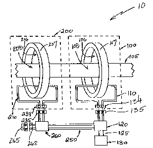
FIG. 1 is a drawing of a circuit having two inductive couplers connected in
series.
FIG. 2 is a schematic diagram of the circuit of FIG. 1.
FIG. 3 is a drawing of a circuit having three inductive couplers connected in
series.
FIG. 4 is a schematic diagram of the circuit of FIG. 3.
DESCRIPTION OF THE INVENTION
Described herein is a technique for communication over a power line. The
technique employs two or more proximal couplers connected electrically in
series
or parallel with one another.
2

CA 02575506 2007-01-29
WO 2006/065340 PCT/US2005/037463
Generally, an inductive coupler includes a split magnetic core and a winding
situated around the core. The core may be configured, for example, with two C-
shaped portions. When the two C-shaped portions are placed together, they form
a cylinder with an aperture extending through the center of the cylinder. The
two
C-shaped portions may be separated and placed on an energized or de-energized
wire so that the wire is routed through the aperture. The wire may be a power
line
or other conductor. The wire, the core, and the winding situated around the
core,
together, form a transformer, where the wire serves as a primary of the
transformer
and the winding around the core serves as a secondary of the transformer. The
secondary may be connected to a modem or other communications equipment
directly or via a surge protection circuit.
PLC employs data signal frequencies greater than or equal to about 1 MHz.
However, a bandpass of an inductive coupler may have a lower cutoff frequency
of greater than 1MHz, and so, the inductive coupler may not provide adequate
performance at signal frequencies down to 1MHz. Increasing the inductance of a
wire passing through the inductive coupler extends the lower cutoff frequency,
thus allowing lower signal frequencies to be used for communications. One
technique of increasing inductance is increasing a number of magnetic cores in
the
coupler. The increase in the number of magnetic cores can be accomplished by a
coupling together of individual inductive couplers.
FIG. 1 is a drawing of a circuit 10 that includes an inductive coupler 100 and
an inductive coupler 200 situated on a conductor 105. Conductor 105 may be,
for
example, a phase conductor of an outside power line, i.e., a power line
external to
a building.
Inductive coupler 100 includes a core 107 and a winding 110. Inductive
coupler 100 is situated on conductor 105 such that conductor 105 is routed
through an aperture 106 in core 107. Together, conductor 105, core 107 and
winding 110 form a transformer where a portion 108 of conductor 105 serves as
a
3

CA 02575506 2007-01-29
WO 2006/065340 PCT/US2005/037463
primary of the transformer, and winding 110 serves as a secondary of the
transformer. Inductive coupler 100 couples a data signal between conductor 105
and winding 110. Winding 110 is connected via connectors 134 and 135 to a
surge protection module 120, which is, in turn, connected via a cable 125 to a
modem 130. In a preferred implementation, connector 135 and cable 125 are
integral parts of surge protection module 120.
Inductive coupler 200 includes a core 207, and a winding 210. Inductive
coupler 200 is situated on conductor 105 such that conductor 105 is routed
through an aperture 206 in core 207. Together, conductor 105, core 207 and
winding 210 form a transformer, where a portion 208 of conductor 105 serves as
a
primary of the transformer, and winding 210 serves as a secondary of the
transformer. Inductive coupler 200 couples a data signal between conductor 105
and winding 210. Winding 210 is connected via connectors 234 and 235, to a
connection module 260. Connection module 260 connects winding 210, via a
jumper connection 262 and a jumper 265, to a cable 250, which connects to
surge
protection module 120.
FIG. 2 is a schematic diagram of circuit 10. FIG. 2 shows that surge
protection module 120 includes a connection section 121 and a surge
suppression
circuit 122. Connection section 121 connects winding 110 in series with
winding
210. Thus, the secondary of inductive coupler 100 is connected in series with
the
secondary of inductive coupler 200. This connection is arranged such that
induced voltages from these secondaries add in the same phase, consistent with
the direction of the primary wires, as indicated in FIG. 2B by phasing dots.
Couplers 100 and 200 need not be any particular distance from one another
to perform as described herein. However, for best performance, couplers 100
and
200 should be adjacent to each other, and longitudinal separation should not
exceed one tenth of a wavelength, at the highest signal frequency in use.
4

CA 02575506 2007-01-29
WO 2006/065340 PCT/US2005/037463
Surge suppression circuit 122 protects modem 130 from voltage that can
result from an excessive surge current on conductor 105, such as in a case of
a
lightening strike on conductor 105. Surge suppression circuit 122 can be
implemented, for example, with a gas tube surge arrestor or an avalanche diode
surge arrestor.
FIG. 3 is a drawing of a circuit 20, which is an enhancement of circuit 10.
Circuit 20 includes an inductive coupler 300. Inductive coupler 300, similarly
to
couplers 100 and 200, includes a winding 310 that serves as a secondary of a
transformer. FIG. 4 is a schematic diagram of circuit 20.
In circuit 20, in contrast to circuit 10, jumper connection 262 is not jumped,
but is instead, connected to winding 310 via a connection module 360.
Connection module 360 is terminated by a jumper 350.
A daisy chain is a collection of standardized modules connected to each
other in a chain. Typically, an output cable of one module is plugged into an
input
connector of the next module in the chain. Thus, inductive couplers 100, 200
and
300 are daisy-chained.
The chain of inductive couplers 100, 200 and 300 shares surge suppression
circuit 122 (see FIG. 2). Thus, only one surge suppression circuit 122 is
required.
This arrangement is less expensive than equipping each inductive coupler 100,
200 and 300 with its own surge suppression circuit 122, and may reduce RF
signal
loss for the aggregate of inductive couplers 100, 200 and 300.
Note that in FIGS. 1 and 2 cable 250 is represented as being hard wired to
surge protection module 120 and connection module 260. In contrast, in FIGS. 3
and 4, connections between connection module 260 and surge protection module
120 are made via connectors 340 and 345.
5

CA 02575506 2007-01-29
WO 2006/065340 PCT/US2005/037463
Any number of inductive couplers may be daisy chained. When the
inductive couplers are chained via connection modules (e.g., connection
modules
260 and 360) the last connection module in the chain (e.g., connection module
360) has its jumper terminals shorted together.
While a series connection of inductive couplers 100, 200 and 300 is
illustrated in FIGS. 1- 4, a parallel connection may be implemented along the
same lines.
6

Representative Drawing
A single figure which represents the drawing illustrating the invention.
Administrative Status

2024-08-01:As part of the Next Generation Patents (NGP) transition, the Canadian Patents Database (CPD) now contains a more detailed Event History, which replicates the Event Log of our new back-office solution.

Please note that "Inactive:" events refers to events no longer in use in our new back-office solution.

For a clearer understanding of the status of the application/patent presented on this page, the site Disclaimer , as well as the definitions for Patent , Event History , Maintenance Fee  and Payment History  should be consulted.

Event History

Description Date
Application Not Reinstated by Deadline 2011-10-17
Time Limit for Reversal Expired 2011-10-17
Inactive: Abandon-RFE+Late fee unpaid-Correspondence sent 2010-10-18
Deemed Abandoned - Failure to Respond to Maintenance Fee Notice 2010-10-18
Inactive: IPRP received 2008-02-22
Letter Sent 2007-04-23
Inactive: Cover page published 2007-04-13
Inactive: Courtesy letter - Evidence 2007-04-03
Inactive: Notice - National entry - No RFE 2007-03-26
Inactive: Single transfer 2007-03-05
Application Received - PCT 2007-02-23
National Entry Requirements Determined Compliant 2007-01-29
Application Published (Open to Public Inspection) 2006-06-22

Abandonment History

Abandonment Date Reason Reinstatement Date
2010-10-18

Maintenance Fee

The last payment was received on 2009-09-28

Note : If the full payment has not been received on or before the date indicated, a further fee may be required which may be one of the following

  • the reinstatement fee;
  • the late payment fee; or
  • additional fee to reverse deemed expiry.

Please refer to the CIPO Patent Fees web page to see all current fee amounts.

Fee History

Fee Type Anniversary Year Due Date Paid Date
Basic national fee - standard 2007-01-29
Registration of a document 2007-03-05
MF (application, 2nd anniv.) - standard 02 2007-10-17 2007-10-16
MF (application, 3rd anniv.) - standard 03 2008-10-17 2008-10-03
MF (application, 4th anniv.) - standard 04 2009-10-19 2009-09-28
Owners on Record

Note: Records showing the ownership history in alphabetical order.

Current Owners on Record
AMBIENT CORPORATION
Past Owners on Record
RAM RAO
YEHUDA CERN
Past Owners that do not appear in the "Owners on Record" listing will appear in other documentation within the application.
Documents

To view selected files, please enter reCAPTCHA code :


To view images, click a link in the Document Description column. To download the documents, select one or more checkboxes in the first column and then click the "Download Selected in PDF format (Zip Archive)" or the "Download Selected as Single PDF" button.

List of published and non-published patent-specific documents on the CPD .

If you have any difficulty accessing content, you can call the Client Service Centre at 1-866-997-1936 or send them an e-mail at CIPO Client Service Centre.


Document
Description 
Date
(yyyy-mm-dd) 
Number of pages   Size of Image (KB) 
Abstract 2007-01-29 1 66
Description 2007-01-29 6 230
Claims 2007-01-29 3 79
Drawings 2007-01-29 4 61
Representative drawing 2007-04-12 1 11
Cover Page 2007-04-13 1 43
Notice of National Entry 2007-03-26 1 192
Courtesy - Certificate of registration (related document(s)) 2007-04-23 1 105
Reminder of maintenance fee due 2007-06-19 1 112
Reminder - Request for Examination 2010-06-21 1 119
Courtesy - Abandonment Letter (Maintenance Fee) 2010-12-13 1 173
Courtesy - Abandonment Letter (Request for Examination) 2011-01-24 1 165
PCT 2007-01-29 2 80
Correspondence 2007-03-26 1 28
PCT 2007-01-30 4 164