Sélection de la langue

Search

Sommaire du brevet 2575506 

Énoncé de désistement de responsabilité concernant l'information provenant de tiers

Une partie des informations de ce site Web a été fournie par des sources externes. Le gouvernement du Canada n'assume aucune responsabilité concernant la précision, l'actualité ou la fiabilité des informations fournies par les sources externes. Les utilisateurs qui désirent employer cette information devraient consulter directement la source des informations. Le contenu fourni par les sources externes n'est pas assujetti aux exigences sur les langues officielles, la protection des renseignements personnels et l'accessibilité.

Disponibilité de l'Abrégé et des Revendications

L'apparition de différences dans le texte et l'image des Revendications et de l'Abrégé dépend du moment auquel le document est publié. Les textes des Revendications et de l'Abrégé sont affichés :

  • lorsque la demande peut être examinée par le public;
  • lorsque le brevet est émis (délivrance).
(12) Demande de brevet: (11) CA 2575506
(54) Titre français: AGENCEMENT DE COUPLEURS INDUCTIFS EN SERIE POUR TRANSMISSION DE DONNEES
(54) Titre anglais: ARRANGEMENT OF DAISY CHAINED INDUCTIVE COUPLERS FOR DATA COMMUNICATION
Statut: Réputée abandonnée et au-delà du délai pour le rétablissement - en attente de la réponse à l’avis de communication rejetée
Données bibliographiques
(51) Classification internationale des brevets (CIB):
  • G08B 1/08 (2006.01)
  • H01R 13/66 (2006.01)
  • H02J 3/02 (2006.01)
  • H02J 3/34 (2006.01)
  • H04B 3/54 (2006.01)
  • H04M 11/04 (2006.01)
  • H04Q 1/30 (2006.01)
(72) Inventeurs :
  • CERN, YEHUDA (Etats-Unis d'Amérique)
  • RAO, RAM (Etats-Unis d'Amérique)
(73) Titulaires :
  • AMBIENT CORPORATION
(71) Demandeurs :
  • AMBIENT CORPORATION (Etats-Unis d'Amérique)
(74) Agent: BORDEN LADNER GERVAIS LLP
(74) Co-agent:
(45) Délivré:
(86) Date de dépôt PCT: 2005-10-17
(87) Mise à la disponibilité du public: 2006-06-22
Licence disponible: S.O.
Cédé au domaine public: S.O.
(25) Langue des documents déposés: Anglais

Traité de coopération en matière de brevets (PCT): Oui
(86) Numéro de la demande PCT: PCT/US2005/037463
(87) Numéro de publication internationale PCT: WO 2006065340
(85) Entrée nationale: 2007-01-29

(30) Données de priorité de la demande:
Numéro de la demande Pays / territoire Date
11/011,574 (Etats-Unis d'Amérique) 2004-12-14

Abrégés

Abrégé français

L'invention concerne un agencement de coupleurs inductifs. L'agencement comprend un premier coupleur inductif sur un conducteur, et un second coupleur inductif sur ledit conducteur. Le premier coupleur inductif comporte un premier enroulement destiné à un signal de données, et le second coupleur inductif comporte un second enroulement destiné au signal de données. Cet agencement comprend aussi un module de connexion qui connecte le premier enroulement au second.


Abrégé anglais


There is provided an arrangement (10) of inductive couplers (100, 200). The
arrangement includes a first inductive coupler (100) on a conductor (105), and
a second inductive coupler (200) on the conductor (105). The first inductive
coupler (100) has a first winding (110) for a data signal, and the second
inductive coupler (200) has a second winding (210) for the data signal. The
arrangement also includes a connection module (260) that connects the first
winding to the second winding.

Revendications

Note : Les revendications sont présentées dans la langue officielle dans laquelle elles ont été soumises.


WHAT IS CLAIMED IS:
1. A system comprising:
a first inductive coupler on a conductor, wherein said first inductive coupler
has a first winding for a data signal;
a second inductive coupler on said conductor, wherein said second inductive
coupler has a second winding for said data signal; and
a connection module that connects said first winding to said second
winding.
2. The system of claim 1, wherein said connection module connects said
first winding and said second winding to a communications device.
3. The system of claim 1, wherein said connection module connects said
first winding and said second winding to a surge suppression circuit.
4. The system of claim 1, wherein said connection module connects said
first winding and said second winding in series with one another.
5. The system of claim 1, wherein said connection module connects said
first winding and said second winding in parallel with one another.
6. The system of claim 1, wherein said connection module connects said
first winding and said second winding in phase with one other.
7. The system of claim 1,
wherein said conductor is a power line, and
wherein said data signal has a frequency greater than or equal to about 1
megahertz.
7

8. The system of claim 1,
wherein said first inductive coupler couples said data signal between said
conductor and said first winding, and
wherein said second inductive coupler couples said data signal between said
conductor and said second winding.
9. A method comprising:
situating a first inductive coupler on a conductor, wherein said first
inductive coupler has a winding for a data signal;
situating a second inductive couple on said conductor, wherein said second
inductive coupler has a winding for said data signal; and
connecting said winding of said first inductive coupler to said winding of
said second inductive coupler.
10. The method of claim 9, wherein said connecting comprises connecting
said first winding and said second winding to a communications device.
11. The method of claim 9, wherein said connecting comprises connecting
said first winding and said second winding to a surge suppression circuit.
12. The method of claim 9, wherein said connecting comprises connecting
said first winding and said second winding in series with one another.
13. The method of claim 9, wherein said connecting comprises connecting
said first winding and said second winding in parallel with one another.
14. The method of claim 9, wherein said connecting comprises connecting
said first winding and said second winding in phase with one other.
15. The method of claim 9,
wherein said conductor is a power line, and
8

wherein said data signal has a frequency greater than or equal to about 1
megahertz.
16. The method of claim 9,
wherein said first inductive coupler couples said data signal between said
conductor and said first winding, and
wherein said second inductive coupler couples said data signal between said
conductor and said second winding.
9

Description

Note : Les descriptions sont présentées dans la langue officielle dans laquelle elles ont été soumises.

CA 02575506 2007-01-29
WO 2006/065340 PCT/US2005/037463
ARRANGEMENT OF DAISY CHAINED INDUCTIVE COUPLERS
FOR DATA COMMUNICATION
BACKGROUND OF THE INVENTION
1. Field of the Invention
The present invention relates to data communications. It is particularly
suitable for power line communications (PLC) between locations having a
common electrical distribution system.
2. Description of the Related Art
PLC, also known as Broadband over Power Line (BoPL), is a technology
that encompasses transmission of data at high frequencies through existing
electric
power lines, i.e., conductors used for carrying a power current. Power current
is
typically transmitted through power lines at a frequency in the range of 50-60
hertz (Hz). In low voltage lines, power current is transmitted with a voltage
between about 90 to 600 volts, and in medium voltage lines, power current is
transmitted with a voltage between about 2,400 volts to 35,000 volts. The
frequency of the data signals is greater than or equal to about 1 megahertz
(MHz),
and the voltage of the data signal ranges from a fraction of a volt to a few
tens of
volts. Data communication can employ various modulation schemes such as
amplitude modulation, frequency modulation, pulse modulation or spread
spectrum modulation.
An inductive coupler couples PLC signals to and from a power line. The
inductive coupler has a high pass frequency characteristic. Therefore, a
signal
attenuation or path loss through the inductive coupler may be excessive below
a
lower cutoff frequency of the inductive coupler.
1

CA 02575506 2007-01-29
WO 2006/065340 PCT/US2005/037463
It is desirable to provide for PLC communications over a range of
frequencies that extends below a lower cutoff frequency of an inductive
coupler.
SUMMARY OF THE INVENTION
There is provided an arrangement of inductive couplers. The arrangement
includes a first inductive coupler on a conductor, and a second inductive
coupler
on the conductor. The first inductive coupler has a first winding for a data
signal,
and the second inductive coupler has a second winding for the data signal. The
arrangement also includes a connection module that connects the first winding
to
the second winding.
BRIEF DESCRIPTION OF THE DRAWINGS
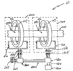
FIG. 1 is a drawing of a circuit having two inductive couplers connected in
series.
FIG. 2 is a schematic diagram of the circuit of FIG. 1.
FIG. 3 is a drawing of a circuit having three inductive couplers connected in
series.
FIG. 4 is a schematic diagram of the circuit of FIG. 3.
DESCRIPTION OF THE INVENTION
Described herein is a technique for communication over a power line. The
technique employs two or more proximal couplers connected electrically in
series
or parallel with one another.
2

CA 02575506 2007-01-29
WO 2006/065340 PCT/US2005/037463
Generally, an inductive coupler includes a split magnetic core and a winding
situated around the core. The core may be configured, for example, with two C-
shaped portions. When the two C-shaped portions are placed together, they form
a cylinder with an aperture extending through the center of the cylinder. The
two
C-shaped portions may be separated and placed on an energized or de-energized
wire so that the wire is routed through the aperture. The wire may be a power
line
or other conductor. The wire, the core, and the winding situated around the
core,
together, form a transformer, where the wire serves as a primary of the
transformer
and the winding around the core serves as a secondary of the transformer. The
secondary may be connected to a modem or other communications equipment
directly or via a surge protection circuit.
PLC employs data signal frequencies greater than or equal to about 1 MHz.
However, a bandpass of an inductive coupler may have a lower cutoff frequency
of greater than 1MHz, and so, the inductive coupler may not provide adequate
performance at signal frequencies down to 1MHz. Increasing the inductance of a
wire passing through the inductive coupler extends the lower cutoff frequency,
thus allowing lower signal frequencies to be used for communications. One
technique of increasing inductance is increasing a number of magnetic cores in
the
coupler. The increase in the number of magnetic cores can be accomplished by a
coupling together of individual inductive couplers.
FIG. 1 is a drawing of a circuit 10 that includes an inductive coupler 100 and
an inductive coupler 200 situated on a conductor 105. Conductor 105 may be,
for
example, a phase conductor of an outside power line, i.e., a power line
external to
a building.
Inductive coupler 100 includes a core 107 and a winding 110. Inductive
coupler 100 is situated on conductor 105 such that conductor 105 is routed
through an aperture 106 in core 107. Together, conductor 105, core 107 and
winding 110 form a transformer where a portion 108 of conductor 105 serves as
a
3

CA 02575506 2007-01-29
WO 2006/065340 PCT/US2005/037463
primary of the transformer, and winding 110 serves as a secondary of the
transformer. Inductive coupler 100 couples a data signal between conductor 105
and winding 110. Winding 110 is connected via connectors 134 and 135 to a
surge protection module 120, which is, in turn, connected via a cable 125 to a
modem 130. In a preferred implementation, connector 135 and cable 125 are
integral parts of surge protection module 120.
Inductive coupler 200 includes a core 207, and a winding 210. Inductive
coupler 200 is situated on conductor 105 such that conductor 105 is routed
through an aperture 206 in core 207. Together, conductor 105, core 207 and
winding 210 form a transformer, where a portion 208 of conductor 105 serves as
a
primary of the transformer, and winding 210 serves as a secondary of the
transformer. Inductive coupler 200 couples a data signal between conductor 105
and winding 210. Winding 210 is connected via connectors 234 and 235, to a
connection module 260. Connection module 260 connects winding 210, via a
jumper connection 262 and a jumper 265, to a cable 250, which connects to
surge
protection module 120.
FIG. 2 is a schematic diagram of circuit 10. FIG. 2 shows that surge
protection module 120 includes a connection section 121 and a surge
suppression
circuit 122. Connection section 121 connects winding 110 in series with
winding
210. Thus, the secondary of inductive coupler 100 is connected in series with
the
secondary of inductive coupler 200. This connection is arranged such that
induced voltages from these secondaries add in the same phase, consistent with
the direction of the primary wires, as indicated in FIG. 2B by phasing dots.
Couplers 100 and 200 need not be any particular distance from one another
to perform as described herein. However, for best performance, couplers 100
and
200 should be adjacent to each other, and longitudinal separation should not
exceed one tenth of a wavelength, at the highest signal frequency in use.
4

CA 02575506 2007-01-29
WO 2006/065340 PCT/US2005/037463
Surge suppression circuit 122 protects modem 130 from voltage that can
result from an excessive surge current on conductor 105, such as in a case of
a
lightening strike on conductor 105. Surge suppression circuit 122 can be
implemented, for example, with a gas tube surge arrestor or an avalanche diode
surge arrestor.
FIG. 3 is a drawing of a circuit 20, which is an enhancement of circuit 10.
Circuit 20 includes an inductive coupler 300. Inductive coupler 300, similarly
to
couplers 100 and 200, includes a winding 310 that serves as a secondary of a
transformer. FIG. 4 is a schematic diagram of circuit 20.
In circuit 20, in contrast to circuit 10, jumper connection 262 is not jumped,
but is instead, connected to winding 310 via a connection module 360.
Connection module 360 is terminated by a jumper 350.
A daisy chain is a collection of standardized modules connected to each
other in a chain. Typically, an output cable of one module is plugged into an
input
connector of the next module in the chain. Thus, inductive couplers 100, 200
and
300 are daisy-chained.
The chain of inductive couplers 100, 200 and 300 shares surge suppression
circuit 122 (see FIG. 2). Thus, only one surge suppression circuit 122 is
required.
This arrangement is less expensive than equipping each inductive coupler 100,
200 and 300 with its own surge suppression circuit 122, and may reduce RF
signal
loss for the aggregate of inductive couplers 100, 200 and 300.
Note that in FIGS. 1 and 2 cable 250 is represented as being hard wired to
surge protection module 120 and connection module 260. In contrast, in FIGS. 3
and 4, connections between connection module 260 and surge protection module
120 are made via connectors 340 and 345.
5

CA 02575506 2007-01-29
WO 2006/065340 PCT/US2005/037463
Any number of inductive couplers may be daisy chained. When the
inductive couplers are chained via connection modules (e.g., connection
modules
260 and 360) the last connection module in the chain (e.g., connection module
360) has its jumper terminals shorted together.
While a series connection of inductive couplers 100, 200 and 300 is
illustrated in FIGS. 1- 4, a parallel connection may be implemented along the
same lines.
6

Dessin représentatif
Une figure unique qui représente un dessin illustrant l'invention.
États administratifs

2024-08-01 : Dans le cadre de la transition vers les Brevets de nouvelle génération (BNG), la base de données sur les brevets canadiens (BDBC) contient désormais un Historique d'événement plus détaillé, qui reproduit le Journal des événements de notre nouvelle solution interne.

Veuillez noter que les événements débutant par « Inactive : » se réfèrent à des événements qui ne sont plus utilisés dans notre nouvelle solution interne.

Pour une meilleure compréhension de l'état de la demande ou brevet qui figure sur cette page, la rubrique Mise en garde , et les descriptions de Brevet , Historique d'événement , Taxes périodiques et Historique des paiements devraient être consultées.

Historique d'événement

Description Date
Demande non rétablie avant l'échéance 2011-10-17
Le délai pour l'annulation est expiré 2011-10-17
Inactive : Abandon.-RE+surtaxe impayées-Corr envoyée 2010-10-18
Réputée abandonnée - omission de répondre à un avis sur les taxes pour le maintien en état 2010-10-18
Inactive : IPRP reçu 2008-02-22
Lettre envoyée 2007-04-23
Inactive : Page couverture publiée 2007-04-13
Inactive : Lettre de courtoisie - Preuve 2007-04-03
Inactive : Notice - Entrée phase nat. - Pas de RE 2007-03-26
Inactive : Transfert individuel 2007-03-05
Demande reçue - PCT 2007-02-23
Exigences pour l'entrée dans la phase nationale - jugée conforme 2007-01-29
Demande publiée (accessible au public) 2006-06-22

Historique d'abandonnement

Date d'abandonnement Raison Date de rétablissement
2010-10-18

Taxes périodiques

Le dernier paiement a été reçu le 2009-09-28

Avis : Si le paiement en totalité n'a pas été reçu au plus tard à la date indiquée, une taxe supplémentaire peut être imposée, soit une des taxes suivantes :

  • taxe de rétablissement ;
  • taxe pour paiement en souffrance ; ou
  • taxe additionnelle pour le renversement d'une péremption réputée.

Veuillez vous référer à la page web des taxes sur les brevets de l'OPIC pour voir tous les montants actuels des taxes.

Historique des taxes

Type de taxes Anniversaire Échéance Date payée
Taxe nationale de base - générale 2007-01-29
Enregistrement d'un document 2007-03-05
TM (demande, 2e anniv.) - générale 02 2007-10-17 2007-10-16
TM (demande, 3e anniv.) - générale 03 2008-10-17 2008-10-03
TM (demande, 4e anniv.) - générale 04 2009-10-19 2009-09-28
Titulaires au dossier

Les titulaires actuels et antérieures au dossier sont affichés en ordre alphabétique.

Titulaires actuels au dossier
AMBIENT CORPORATION
Titulaires antérieures au dossier
RAM RAO
YEHUDA CERN
Les propriétaires antérieurs qui ne figurent pas dans la liste des « Propriétaires au dossier » apparaîtront dans d'autres documents au dossier.
Documents

Pour visionner les fichiers sélectionnés, entrer le code reCAPTCHA :


Pour visualiser une image, cliquer sur un lien dans la colonne description du document. Pour télécharger l'image (les images), cliquer l'une ou plusieurs cases à cocher dans la première colonne et ensuite cliquer sur le bouton "Télécharger sélection en format PDF (archive Zip)" ou le bouton "Télécharger sélection (en un fichier PDF fusionné)".

Liste des documents de brevet publiés et non publiés sur la BDBC .

Si vous avez des difficultés à accéder au contenu, veuillez communiquer avec le Centre de services à la clientèle au 1-866-997-1936, ou envoyer un courriel au Centre de service à la clientèle de l'OPIC.


Description du
Document 
Date
(aaaa-mm-jj) 
Nombre de pages   Taille de l'image (Ko) 
Abrégé 2007-01-29 1 66
Description 2007-01-29 6 230
Revendications 2007-01-29 3 79
Dessins 2007-01-29 4 61
Dessin représentatif 2007-04-12 1 11
Page couverture 2007-04-13 1 43
Avis d'entree dans la phase nationale 2007-03-26 1 192
Courtoisie - Certificat d'enregistrement (document(s) connexe(s)) 2007-04-23 1 105
Rappel de taxe de maintien due 2007-06-19 1 112
Rappel - requête d'examen 2010-06-21 1 119
Courtoisie - Lettre d'abandon (taxe de maintien en état) 2010-12-13 1 173
Courtoisie - Lettre d'abandon (requête d'examen) 2011-01-24 1 165
PCT 2007-01-29 2 80
Correspondance 2007-03-26 1 28
PCT 2007-01-30 4 164