Language selection

Search

Patent 2575554 Summary

Third-party information liability

Some of the information on this Web page has been provided by external sources. The Government of Canada is not responsible for the accuracy, reliability or currency of the information supplied by external sources. Users wishing to rely upon this information should consult directly with the source of the information. Content provided by external sources is not subject to official languages, privacy and accessibility requirements.

Claims and Abstract availability

Any discrepancies in the text and image of the Claims and Abstract are due to differing posting times. Text of the Claims and Abstract are posted:

  • At the time the application is open to public inspection;
  • At the time of issue of the patent (grant).
(12) Patent Application: (11) CA 2575554
(54) English Title: NON-METALLIC GEAR PUMP WITH MAGNETIC COUPLING ASSEMBLY
(54) French Title: POMPE A ENGRENAGES NON METALLIQUE AVEC ENSEMBLE D'ACCOUPLEMENT MAGNETIQUE
Status: Dead
Bibliographic Data
(51) International Patent Classification (IPC):
  • F04C 2/18 (2006.01)
  • F04C 2/08 (2006.01)
  • F04C 13/00 (2006.01)
  • F04C 15/00 (2006.01)
(72) Inventors :
  • MUSCARELLA, STEPHEN B. (United States of America)
  • PASCOE, PHILIP T. (United States of America)
(73) Owners :
  • PULSAFEEDER, INC. (United States of America)
(71) Applicants :
  • PULSAFEEDER, INC. (United States of America)
(74) Agent: MACRAE & CO.
(74) Associate agent:
(45) Issued:
(86) PCT Filing Date: 2005-08-01
(87) Open to Public Inspection: 2006-02-09
Examination requested: 2010-07-29
Availability of licence: N/A
(25) Language of filing: English

Patent Cooperation Treaty (PCT): Yes
(86) PCT Filing Number: PCT/US2005/026998
(87) International Publication Number: WO2006/015218
(85) National Entry: 2007-01-30

(30) Application Priority Data:
Application No. Country/Territory Date
60/592,988 United States of America 2004-07-30

Abstracts

English Abstract


A nonmetallic pump with a gear pump assembly having an adapter spool (93)
mounted to an electric motor. The pump assembly is designed to reduce
manufacturing costs and to provide access for many service and maintenance
tasks to be performed without breaking any of the pipe connections. The pump
assembly also includes a splined shaft system (85) and a lubricating fluid
circulation system with spiral grooves (300, 301, 302) located inside a pair
of bearings disposed on opposite sides of the gear flights. The assembly also
includes a replaceable precision liner (67) that surrounds the gear flights to
maintain a tight tolerance for optimal performance of the pump. Also, an O-
ring (73) disposed inside the front cover of the assembly provides for
operation of the pump over a wide temperature variation with relatively loose
manufacturing tolerances.


French Abstract

L'invention concerne une pompe non métallique dotée d'un ensemble de pompe à engrenages comportant une bobine d'adaptateur (93) montée sur un moteur électrique. L'ensemble de pompe est conçu pour réduire les coûts de fabrication et pour fournir un accès à de nombreuses tâches de service et d'entretien à effectuer sans briser une quelconque connexion de tubulure. L'ensemble de pompe inclut également un système d'arbre à nervures et un système de circulation de fluide de lubrification comportant des rainures en spirale (300, 301, 302) situées à l'intérieur d'une paire de roulements disposés sur des côtés opposés des pas d'engrenages. L'ensemble inclut également une chemise de précision (67) remplaçable qui entoure les pas d'engrenages afin de maintenir une tolérance serrée en vue de performances optimales de la pompe. De même, un joint torique (73), placé à l'intérieur du couvercle avant de l'ensemble, permet un fonctionnement de la pompe sur une variation importante de température tout en présentant des tolérances de fabrication relativement lâches.

Claims

Note: Claims are shown in the official language in which they were submitted.


-13-

WHAT IS CLAIMED IS:


1. A gear pump, comprising:

a central housing having a suction side, a discharge
side, a top flange and a bottom flange;

a drive gear assembly disposed in the central housing,
the drive gear assembly comprising a drive shaft having
a plurality of first gear flights extending therefrom;
an idler gear assembly disposed in the central housing
in operative relation to the drive gear assembly, the
idler gear assembly comprising an idler shaft having a
plurality of second gear flights;

a first bearing having a pair of openings defined
therein, the openings capable of receiving the drive
shaft and idler shaft;

a second bearing having a pair of openings defined
therein, the openings capable of receiving the drive
shaft and idler shaft;

a gear insert disposed between the first and second
bearings and sized to fit over the plurality of first
and second gear flights, the gear insert having an inner
wall disposed in spaced apart relation to the gear
flights;


-14-


a cover attached to the top flange of the central
housing and enclosing the drive and idler gear
assemblies;

an adapter spool having a central opening for receiving
a containment can, the adapter spool having a top flange
and a bottom flange, the top flange capable of mating
with the bottom flange of the central housing;

a drive magnet assembly disposed in the adaptor spool;

a driven magnet assembly disposed in the containment can
in operative relation to the drive magnet assembly;

and,
an electric motor coupled to the drive magnet assembly.

2. The gear pump of Claim 1, wherein the drive shaft
further comprises a plurality of splines formed therein.

3. The gear pump of Claim 1, wherein the drive shaft
is ceramic.


4. The gear pump of Claim 1, further comprising: an
O-ring disposed between the second bearing and the
cover.


-15-


5. The gear pump of Claim 1, wherein the bearing has a
fluid circulation groove with an inlet on a side facing
at least one of the first and second bearings.


6. The gear pump of Claim 5, wherein the fluid
circulation groove is disposed in at least one of the
openings in at least one of the first and second
bearings.


7. The gear pump of Claim 6, wherein the fluid
circulation groove comprises a spiral pathway extending
through the opening in the bearing.


8. The gear pump of Claim 5, wherein each opening in
the bearing has a first inlet on a first side and a
second inlet on a second side disposed opposite the
first side.


9. The gear pump of Claim 8, wherein the drive shaft
has an odd number of flights such that one of the first
and second inlets is covered when the other of the first
and second inlets is uncovered.


-16-


10. The gear pump of Claim 8, wherein the idler shaft
has an odd number of flights such that one of the first
and second inlets is covered when the other of the first
and second inlets is uncovered.


11. The gear pump of Claim 8, wherein the first and
second inlets are approximately 180 degrees apart.

12. The gear pump of Claim 8, wherein as the first
inlet is exposed on a suction side of the drive gear the
second inlet is exposed on a discharge side of the idler
gear.


13. The gear pump of Claim 1, further comprising
universal flanges on the suction and discharge ports.

14. The gear pump of Claim 1, wherein the containment
can fits into a recessed portion in the adapter spool
such that an end of the containment can extends beyond
an end of the adapter spool.


15. The gear pump of Claim 14, wherein the central
housing has a recessed portion that receives the end of


-17-

the containment can.


16. A gear pump, comprising:

a central housing having a suction side, a discharge
side, a top flange and a bottom flange;

a drive gear assembly disposed in the central housing,
the drive gear assembly comprising a drive shaft having
a plurality of first gear flights extending therefrom;
an idler gear assembly disposed in the central housing
in operative relation to the drive gear assembly, the
idler gear assembly comprising an idler shaft having a
plurality of second gear flights;

a first bearing having. inner walls defining a pair of
openings, the openings capable of receiving the drive
shaft and idler shaft, each opening in the first bearing
having a first fluid circulation inlet on a first side
and having a second fluid circulation inlet on a second
side disposed opposite from the first side, the first
fluid circulation inlet leading to a fluid circulation
groove defined in the inner walls of the first bearing
and extending from one end of the first bearing to the
opposite end;

a second bearing having inner walls defining a pair of


-18-


openings, the openings capable of receiving the drive
shaft and idler shaft, each opening in the second
bearing having a first fluid circulation inlet on a
first side and having a second fluid circulation inlet
on a second side disposed opposite from the first side,
the first fluid circulation inlet leading to a fluid
circulation groove defined in the inner walls of the
second bearing and extending from one end of the second
bearing to the opposite end;

a gear insert disposed between the first and second
bearings and sized to fit over the plurality of first
and second gear flights, the gear insert having an inner
wall disposed in spaced apart relation to the gear
flights;

a cover attached to the top flange of the central
housing and enclosing the drive and idler gear
assemblies;

an adapter spool having a central opening for receiving
a containment can, the adapter spool having a top flange
and a bottom flange, the top flange capable of mating
with the bottom flange of the central housing;

a drive magnet assembly disposed in the adaptor spool;

a driven magnet assembly disposed in the containment can


-19-


in operative relation to the drive magnet assembly;

an electric motor coupled to the drive magnet assembly;
and,

wherein the first and second gear flights are disposed
such that when the first inlet is exposed on a suction
side of the drive gear the second inlet is exposed on a
discharge side of the idler gear.


17. The gear pump of Claim 16, wherein the first and
second inlets are approximately 180 degrees apart.


18. The gear pump of Claim 16, wherein the drive shaft
and idler shaft have an odd number of flights.


19. The gear pump of Claim 16, wherein the drive shaft
further comprises a plurality of splines formed therein.

20. The gear pump of Claim 1, wherein the drive shaft
is ceramic.


21. The gear pump of Claim 16, further comprising:

an O-ring disposed between the second bearing and
the cover.


-20-


22. The gear pump of Claim 16, further comprising:
universal flanges on the suction and discharge sides.

23. The gear pump of Claim 16, wherein the containment
can fits into a recessed portion in the adapter spool
such that an end of the containment can extends beyond
an end of the adapter spool.


24. The gear pump of Claim 23, wherein the central
housing has a recessed portion that receives the end of
the containment can.


25. A gear pump, comprising:

a central housing having a suction side, a discharge
side, a top flange and a bottom flange;

a drive gear assembly disposed in the central housing,
the drive gear assembly comprising a drive shaft having
a plurality of first gear flights extending therefrom,
the drive shaft having a plurality of splines formed
therein;

an idler gear assembly disposed in the central housing
in operative relation to the drive gear assembly, the


-21-


idler gear assembly comprising an idler shaft having a
plurality of second gear flights;

a first bearing having a pair of openings defined
therein, the openings capable of receiving the drive
shaft and idler shaft;

a second bearing having a pair of openings defined
therein, the openings capable of receiving the drive
shaft and idler shaft;

a gear insert disposed between the first and second
bearings and sized to fit over the plurality of first
and second gear flights, the gear insert having an inner
wall disposed in spaced apart relation to the gear
flights;

a cover attached to the top flange of the central
housing and enclosing the drive and idler gear
assemblies;

an O-ring disposed between the second bearing and the
cover;

an adapter spool having a central opening for receiving
a containment can, the adapter spool having a top flange
and a bottom flange, the top flange capable of mating,
with the bottom flange of the central housing;

a drive magnet assembly disposed in the adaptor spool;


-22-


a driven magnet assembly disposed in the containment can
in operative relation to the drive magnet assembly; and,
an electric motor coupled to the drive magnet assembly.

26. The gear pump of Claim 25, wherein the bearing has
a fluid circulation groove with an inlet on a side

facing at least one of the first and second bearings.

27. The gear pump of Claim 26, wherein the fluid
circulation groove is disposed in at least one of the
openings in at least one of the first and second
bearings.


28. The gear pump of Claim 27, wherein the fluid
circulation groove comprises a spiral pathway extending
through the opening in the bearing.


29. The gear pump of Claim 26, wherein each opening in
the bearing has a first inlet on a first side and a
second inlet on a second side disposed opposite the
first side.


30. The gear pump of Claim 29, wherein the drive shaft


-23-


has an odd number of flights such that one of the first
and second inlets is covered when the other of the first
and second inlets is uncovered.


31. The gear pump of Claim 29, wherein the idler shaft
has an odd number of flights such that one of the first
and second inlets is covered when the other of the first
and second inlets is uncovered.


32. The gear pump of Claim 29, wherein the first and
second inlets are approximately 180 degrees apart.

33. The gear pump of Claim 29, wherein as the first
inlet is exposed on a suction side of the drive gear the
second inlet is exposed on a discharge side of the idler
gear.


34. The gear pump of Claim 25, further comprising
universal flanges on the suction and discharge ports.

35. The gear pump of Claim 25, wherein the containment
can fits into a recessed portion in the adapter spool
such that an end of the containment can extends beyond


-24-

an end of the adapter spool.


36. The gear pump of Claim 35, wherein the central
housing has a recessed portion that receives the end of
the containment can.

Description

Note: Descriptions are shown in the official language in which they were submitted.


CA 02575554 2007-01-30
WO 2006/015218 PCT/US2005/026998
GEAR PUMP

CROSS-REFERENCE TO RELATED APPLICATION

This application claims priority to U.S.
Provisional Patent Application No. 60/592,988 filed July
30, 2004, and entitled "Gear Pump," which is

incorporated herein by reference.
FIELD OF THE INVENTION

The present invention pertains to a gear pump.

BACKGROUND OF THE INVENTION

Positive displacement gear pumps can be used for
low.rate metering pump applications. Depending on the
substances to be conveyed, chemical resistance may be a

required characteristic of the materials of construction
for the pump. In order to handle corrosive materials,
the pumps are typically constructed from corrosion
resistant materials such as 316 stainless steel. There
is a need for a non-metallic pump that is easier and

less expensive to manufacture and that is chemically
resistant.

SUMMARY OF THE INVENTION

The present invention meets the above-described


CA 02575554 2007-01-30
WO 2006/015218 PCT/US2005/026998
- 2 -

need by providing a non-metallic pump with a central
housing having a suction side, a discharge side, a top
flange and a bottom flange. A drive gear assembly is
disposed in the central housing. The drive gear

assembly comprises a drive shaft having a plurality of
first gear flights extending therefrom. An idler gear
assembly is disposed in the central housing in operative
relation to the drive gear assembly. The idler gear
assembly, comprises an idler shaft having a plurality of

second gear flights. A first bearing has a pair of
openings defined therein. The openings are capable of
receiving the drive shaft and idler shaft. A second
bearing has a pair of openings defined therein. The
openings are capahle of receiving the drive shaft and

the idler shaft. A gear insert is disposed between the
first and second bearings and is sized to fit over the
plurality of first and second gear flights. The gear
insert has an inner wall disposed in spaced apart

relation to the gear flights. A cover is attached to
the top flange of the central housing and encloses the
drive and idler gear assemblies. An adapter spool has a
central opening for receiving a containment can. The
adapter spool has a top flange and a bottom flange. The


CA 02575554 2007-01-30
WO 2006/015218 PCT/US2005/026998
- 3 -

top flange is capable of mating with the bottom flange
of the central housing. A drive magnet assembly is
disposed in the adaptor spool. A driven magnet assembly
is disposed in the containment can in aperative relation

to the drive magnet assembly. An electric motor is
coupled to the drive magnet assembly.

BRIEF DESCRIPTION OF THE DRAWINGS

The invention is illust=ratedin the drawings in
which like reference characters designate the same or
similar parts throughout the.figures of which:

Fig. 1 is a perspective view of a gea-r pump of the
present invention;

Fig. 2 is a cross-sectional view taken along lines
2-2 of Fig. 1;.

. Fig. 3 is an exploded view of the gear pump
assembly of the present invention;

Fig. 4 is a side elevational,view of the universal
flange of the present,invention;

Fig. 5 is a schematic view of the pump chamber of
the present invention showing the gear teeth and fluid
grooves on the face of the bearing;

Fig. 6 is a side elevational view of one of the


CA 02575554 2007-01-30
WO 2006/015218 PCT/US2005/026998
- 4 -

bearings of the present invention;

Fig. 7 is a cross-sectional view taken along lines
7-7 of Fig. 6;

Fig. 8 is a perspective view of the drive shaft;
and,

Fig. 9 is a partial enlarged view taken from Fig.
2.

DETAILED DESCRIPTION

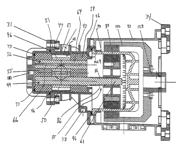
- Referring to FIG. 1, a gear pump assembly 10
includes an adaptor spool 93 mounted t.o.an electric
motor 16. An inlet port 19 and an outlet port 22
include universal flanges 25, 28 with alignment features
as!described in greater detail herein. The assembly 14

is also provided with a front cover 31 that provides-
access to the internal parts. Most maintenance and
service tasks can be performed by opening the front
cover 31 without the need for breaking any of the pipe
connections. The gear pump assembly 10 is constructed

of non-metallic parts as described in greater detail
below.

The adaptor spool 93 has a motor adaptor plate 34
with multiple patterns for use with NEMA or IEC type


CA 02575554 2007-01-30
WO 2006/015218 PCT/US2005/026998
- 5 -

motor enclosures. The center housing 43 can be rotated
in forty-five degree increments to provide a vertical
orientation for the input and output ports 19 and 22.
The base plate 40 has multiple slotted patterns 41 that

match standard motor mounting patterns foor retrofitting
the assembly 10 to match the footprint of existing
installed pumps.

Turning to Figs. 2 and 3, the front cover 31 is
bolted to the center housing 43 and is sealed with a
first 0-ring 46. For ease of installation, the center

housing 43 is provided with nut reta-ining plates 4.7 that
automatically hold the nuts in_place to provide.for
installation of the mounting bolts with a single socket
or wrench. The center housing 43 and the cover 31 form

15= a pump chamber that contains the drive gear assembly.49
and the idler gear assembly 52. The gear assemblies 49,=
52 may be constructed of Ethylene/Tetrafluoroethylen.e
("ETFE") copolymer which is an injection molded
fluoropolymer having chemical resistance properties

suitable for a wide variety of applications. Alternate
non-metallic materials are also suitable as will be
evident to those of ordinary skill in the art. The gear
assemblies 49, 52 have gear teeth 50, 51 that are


CA 02575554 2007-01-30
WO 2006/015218 PCT/US2005/026998
- 6 -

integrally molded on their respective shafts 61, 64.
Shafts 61, 64 are manufactured from non-metallic and
'preferably ceramic materials.

A pair of bearings 55, 58 support the drive shaft
61 and the idler shaft 64. The bearings 55, 58 are,
disposed on opposite sides of the gears 49, 52 and can
be mounted facing in either direction. The bearings 55,
58 include wear plates with fluid grooves on the
surfaces facing the gear teeth 50, 51 as will be

described in further detail herein.

A gear insert or liner 67 is disposed around the
teeth 50, 51 of the respective gear assemblies 49, 52.
The liner 67 is a precision manufactured part having an
inner wall 68 that is disposed in spaced apart relation

--to the teeth on the gear assemblies 49, 52. The gap,
between the end of the teeth of the gear assemblies.49,
:52 and the inner wall 68 is maintained to a tight
tolerance in order to provide optimal performance of the
pump assembly 10. The liner 67 provides for control of

tolerances and easy replacement. The pump assembly 10
can be maintained and restored to its original
performance by replacing the liner 67. The replaceable
liner 67 also prevents the gear teeth from damaging the


CA 02575554 2007-01-30
WO 2006/015218 PCT/US2005/026998
- 7 -

inner wall 71 of the center housing 43 when the bearings
are worn out.

A second 0-ring 73 is disposed inside the front
cover 31 and acts as a spring and takes up any variation
in tolerance resulting from variations in the length of

the housing 43, cover.31, bearings 55, 58 or the liner
67. The 0-ring 73 also compensates for thermal
expansion of the parts. By taking up the tolerance, the
0-ring 73 reduces the cost of manufacturinc.~. the housing

43, cover 31, bearings 55, 58, ancl the liner 67. Under
low pressure, the 0-ring 73 exerts a force against the
outer bearing causing it to press against the liner.
Under-high pressure, the hydraulic fluid forces the
bearings against the liner. An opening 66 is used in

the idler shaft 64 to balance.this hydraulic force
equally from side to side. Other manufacturer's
assemblies typically require highly toleranced metal

-parts:to achieve tolerance control or use narrow
temperature operating ranges. The present invention
allows for use of non-precision non-metallic parts over
a wide temperature range.

The shaft 61 of the drive gear 49 engages with a
driven magnet assembly 83. The shaft 61 may be


CA 02575554 2007-01-30
WO 2006/015218 PCT/US2005/026998
- 8 -

constructed from a ceramic material having chemical
resistance suitable for a wide variety of applications.
The shaft 61 has a.spline system 85 comprising a
plurality of splines 86 machined thereon such that the

5:driven magnet assembly 83 can float on the splines 86
without any,axial load being transmitted to the shaft
61. The spline system 85 eliminates the need for keys
and retaining rings for connecting the shaft to the
driven,magnet. The spline system 85 also spreads out

the load from the driven magnet assembly 83. The driven
magnet assembly 83 is disposed inside a containment can
90 located in an adaptor spool 93. The containment can
-9~0 is sealed against the center housing by a third 0-
ring 96. A drive magnet assembly. 100 is disposed

outside of the containment can 90 and is driven by the
electric motor 16 (Fig. 1) as will be evident to those
of ordinary skill in the art. The drive magnet assembly
100 is coupled to the motor 16 by an interchangeable
:motor hub adaptor 103.

The gear pump assembly 10 may be provided with
flush and drain ports 110 and 113, respectively.

In Fig. 4, universal connection flange 25 is,
provided to allow the pump to mate to ANSI (American


CA 02575554 2007-01-30
WO 2006/015218 PCT/US2005/026998
- 9 -

National Standards Institute) and two different DIN
(Deutsches Institut fur Normung E.V.) size flanges.
This is achieved by incorporating three different
patterns for bolt holes 197. To properly align the

holes 197 on the universal flange 25 concentrically, a
visual indicator is necessary. The visual indicator is
provided by utilizing the outside diameter 200 of the
raised face sealing surface 203 for one size anda
stepped outside diameter with two different diameters

10'= 206, 2-09 for the other two sizes. The raised face
sealing surface insert 293 is Polytetrafluoroethylene
,(Teflon) in the embodiment described, but can be any
compliant material. The insert 2&3 is replaceable in
case of damage so the main housing is not sacrificed.

The insert 203 can also be reversed to present a fresh
side for sealing.

Turning to Figs. 5-7, the pump uses a lubrication
system where there are an odd number of teeth 50, 51 on
the gear assemblies 49 and 52 which alternately cover

- and uncover fluid circulation grooves 300, 301, 302, and
304 to recirculate fluid from the discharge side 303 of
the pump to the intake 306 of the pump. At the bottom
of Fig. 5, the groove 300 on the left hand side of the


CA 02575554 2007-01-30
WO 2006/015218 PCT/US2005/026998
- 10 -

figure is uncovered providing an open flow path. The
groove 304 on the top right hand side of the figure is
also open. When the teeth rotate, the grooves 30a, 30=1,
302, and 304 alternate between the open and closed

position as described below.

As best shown in Figs. 6 and 7, the fluid grooves
300 and 302 start on the face of the bearing 55 and
follow a spiral pathway 306, 308 (grooves 301 and 3G4
have identical spiral pathways that are not shown due to

the direction of the orientation of the cross-section)
to=the opposite side of,the bearing where the pathway
306 ends on the same side.of the bearing. Accord=ingly,
each bearing 55 has a fluid groove that begins at the
front and a fluid groove that begins at the rear.

Because the orientation of,the teeth alternately exposes
the grooves 300, 301, 302, 304 to the pumped fluid
stream, there is never a time when two grooves are
exposed on the same gear. Due to the meshing of the
gear pair, as one groove is exposed on the discharge

side of a gear, an alternate groove is exposed on the
suction side of the second gear. As shown in Fig. 6,
the fluid pathway indicated by arrows 307is as follows:
fluid enters the uncovered groove 304 on the discharge


CA 02575554 2007-01-30
WO 2006/015218 PCT/US2005/026998
- 11 -

side and goes through the spiral pathway to the bottom
of the bearing where it then crosses over to the other
side. The fluid enters the spiral pathway 306 leading
to the uncovered groove 300 on the face at the suction

side. Because of the arrangement of the teeth on the
gears, the pathway alternates from pathway 307 to a
second pathway indicated by arrows 310 in Fig. 6.

Turning to Fig. 8, drive shaft 61 with teeth 50 is
shown in greater detail. The, spline system 85 on drive
shaft 61 is manufactured such,that the ends of the

splines 86 form a smooth transition with the body of the.
'shaft 61. A first feathered section 350 provides a
transition from the body of the shaft 61 to the spline
86. At a position located distal to the first feathered=

section 350, a second feathered section 353 is provided. -
The smooth transition between the spline system 85 and

the shaft 61 eliminates any sharp transitions that cauld
create stress points on the shaft 61.

In Fig. 9, the locating feature of the containment
can 90 is shown in greater detail. The containment can
90 fits into a recessed portion 400 in the adapter spool
93 such that the containment can 90 is disposed above
the top of the adapter spool. The top of the


CA 02575554 2007-01-30
WO 2006/015218 PCT/US2005/026998
- 12 -

containment can 90 mates with a recessed portion 403 in
the center housing 43. Accordingly, the parts locate
themselves during assembly such that once the
containment can 90 is seated properly, the center

housing 43 slides into the correct position and there is
a positive indication of proper alignment due to the
engagement with the top of the containment can 90.

While the invention has been described in
connection with certain embodiments, i.t is not intended
'to limit the scope of the invention to.the particular

!.forms set forth, but, on the contrary,.dt is intended to
cover such alternatives, modifications, and equivalents
as,may be included within the spirit.and scope af the
inventio.n as defined by the appended claims.


Representative Drawing
A single figure which represents the drawing illustrating the invention.
Administrative Status

For a clearer understanding of the status of the application/patent presented on this page, the site Disclaimer , as well as the definitions for Patent , Administrative Status , Maintenance Fee  and Payment History  should be consulted.

Administrative Status

Title Date
Forecasted Issue Date Unavailable
(86) PCT Filing Date 2005-08-01
(87) PCT Publication Date 2006-02-09
(85) National Entry 2007-01-30
Examination Requested 2010-07-29
Dead Application 2013-05-23

Abandonment History

Abandonment Date Reason Reinstatement Date
2007-08-01 FAILURE TO PAY APPLICATION MAINTENANCE FEE 2007-09-19
2012-05-23 R30(2) - Failure to Respond
2012-08-01 FAILURE TO PAY APPLICATION MAINTENANCE FEE

Payment History

Fee Type Anniversary Year Due Date Amount Paid Paid Date
Application Fee $400.00 2007-01-30
Registration of a document - section 124 $100.00 2007-04-11
Reinstatement: Failure to Pay Application Maintenance Fees $200.00 2007-09-19
Maintenance Fee - Application - New Act 2 2007-08-01 $100.00 2007-09-19
Maintenance Fee - Application - New Act 3 2008-08-01 $100.00 2008-07-23
Maintenance Fee - Application - New Act 4 2009-08-03 $100.00 2009-07-27
Request for Examination $800.00 2010-07-29
Maintenance Fee - Application - New Act 5 2010-08-02 $200.00 2010-08-02
Maintenance Fee - Application - New Act 6 2011-08-01 $200.00 2011-07-26
Owners on Record

Note: Records showing the ownership history in alphabetical order.

Current Owners on Record
PULSAFEEDER, INC.
Past Owners on Record
MUSCARELLA, STEPHEN B.
PASCOE, PHILIP T.
Past Owners that do not appear in the "Owners on Record" listing will appear in other documentation within the application.
Documents

To view selected files, please enter reCAPTCHA code :


To view images, click a link in the Document Description column. To download the documents, select one or more checkboxes in the first column and then click the "Download Selected in PDF format (Zip Archive)" or the "Download Selected as Single PDF" button.

List of published and non-published patent-specific documents on the CPD .

If you have any difficulty accessing content, you can call the Client Service Centre at 1-866-997-1936 or send them an e-mail at CIPO Client Service Centre.


Document
Description 
Date
(yyyy-mm-dd) 
Number of pages   Size of Image (KB) 
Representative Drawing 2007-04-13 1 41
Abstract 2007-01-30 1 92
Claims 2007-01-30 12 309
Drawings 2007-01-30 8 248
Description 2007-01-30 12 385
Cover Page 2007-04-16 1 78
Assignment 2007-04-11 5 232
PCT 2007-01-30 3 85
Assignment 2007-01-30 3 91
Correspondence 2007-03-28 1 26
Fees 2007-09-19 1 35
Prosecution-Amendment 2010-07-29 1 28
Fees 2010-08-03 1 27
Prosecution-Amendment 2010-08-26 1 30
Prosecution-Amendment 2011-11-23 2 59