Note: Descriptions are shown in the official language in which they were submitted.
CA 02575667 2007-01-30
WO 2006/036337 PCT/US2005/028909
LASER HANDPIECE ARCHITECTURE AND METHODS
CROSS-REFERENCE TO RELATED APPLICATIONS
This application claims the benefit of U.S. Provisional Application No.
60/601,416, filed August 12, 2004 and entitled, LASER HANDPIECE
ARCHITECTURE AND METHODS and of U.S. Provisional Application No.
60/610,760, filed September 17, 2004 and entitled, LASER HANDPIECE
ARCHITECTURE AND METHODS, the entire contents of both which are incorporated
herein by reference. This application is a continuation-in-part of U.S.
Application No.
11/186,409 (Att. Docket BI9798CIP), filed July 20, 2005 and entitled CONTRA-
ANGLE ROTATING HANDPIECE HAVING TACTILE-FEEDBACK TIP FERRULE,
the entire contents of which are incorporated herein by reference.
BACKGROUND OF THE INVENTION
1. Field of the Invention
The present invention relates generally to electromagnetic energy devices and,
more particularly, to cutting, treatment and illumination devices that
transmit
electromagnetic energy toward target surfaces.
2. Description of Related Art
Electromagnetic energy devices are employed in a variety of applications. For
example, a simple incandescent light may be used to illuminate an area with
electromagnetic energy in a form of visible light. Another form of
electromagnetic
energy, such as a laser beam, may be used to illuminate an area, to identify a
target, or to
deliver concentrated energy to a target in order to perform various procedures
such as
melting, cutting, or the like.
Certain medical devices may deliver electromagnetic energy to a target surface
such as,
for example, an eye, in order to correct a deficiency in visual acuity. Other
medical
devices may direct electromagnetic energy toward a surface of a tooth to
perform, for
example, a cutting operation. Endoscopic devices can be used to enhance
visualization
of internal parts of, for example, a human body in order to detect and/or
remove diseased
Page 1 of 32
CA 02575667 2007-01-30
WO 2006/036337 PCT/US2005/028909
tissue. Constructions of these devices may vary, while underlying
functionalities or
goals, including, for example, the provision of efficient operation by
supplying optimal
illumination without obstructing a user's access or view and/or the provision
of reliable
operation to ensure reproducibility and favorable procedural results, are
often shared.
A need exists in the prior art to efficiently and reliably transmit various
types of
electromagnetic energy to and from target surfaces in order, for example, to
enhance
visualization and treatments of the target surfaces.
SUMMARY OF THE INVENTION
The present invention addresses these needs by providing a laser handpiece
that
connects to an electromagnetic energy base unit (e.g., a laser base unit). The
invention
herein disclosed comprises, according to an exemplary embodiment, a laser
handpiece
having an elongate portion that receives laser energy, illumination light,
excitation light,
spray water, spray air, and cooling air from a connector that connects to the
laser base
unit. The handpiece further comprises a handpiece tip formed as an extension
of the
elongate portion, the handpiece tip being capable of directing laser energy to
a target
surface. An embodiment of the elongate portion comprises a plurality of
optical fibers.
As used herein, "optical fiber" refers to any electromagnetic energy (e.g.,
light)
transmitting medium (e.g., fiber) that is able to transmit light from one end
of the fiber to
another end of the fiber. The light transmission may be passive or it may
include one or
more light altering elements to influence the way light is emitted from the
optical fiber.,
Optical fibers can be used to transmit any type of light, including visible
light, infrared
light, blue light, laser light, and the like. Optical fibers may be hollow or
solid, and may
include one or more reflectors within bodies of the fibers to control
transmission and
ernission of light from the optical fibers.
Another embodiment of the present invention comprises a laser device that
includes a laser base unit, a connector that connects to the laser base unit,
and a conduit
that connects to the connector. Further, a laser handpiece connects to the
conduit, the
laser handpiece being capable of receiving laser energy, illumination light,
excitation
light, spray water, spray air, and cooling air from the laser base unit.
An illumination device in accordance with an aspect of the present invention
includes a unitary distal end (output portion) and a split proximal end (input
portion). As
used herein, "distal end" refers to an end of an illumination device that is
closest to a
Page 2 of 32
CA 02575667 2007-01-30
WO 2006/036337 PCT/US2005/028909
target surface, and "proximal end" refers to an end of an illumination device
that is
closest to a power source or other source of electromagnetic energy. The
illumination
device can include a plurality of different sized optical fibers depending on
a particular
application for which the illumination device is utilized. In illustrative
embodiments,
and as disclosed herein, the proximal end of the illumination device includes
three
proximal end members configured to accommodate three sets of optical fibers.
Another illumination device in accordance with an additional aspect of the
present invention includes a plurality of sets of optical fibers configured to
emit
electromagnetic energy from the distal end of the illumination device toward a
target
surface. The device further may include at least one optical fiber configured
to receive
electromagnetic energy from the target surface and transmit the energy to the
proximal
end of the illumination device. The electromagnetic energy transmitted to the
proximal
end of the illumination device can be used as a signal for further analysis.
In another implementation of the present invention, an illumination device
includes a handpiece having a reflector. The reflector is constructed to
reflect both laser
energy, such as light provided by an erbium laser, and visible light, such as
blue light,
toward a target surface _ In an illustrated embodiment, as disclosed herein,
the reflector
includes a plurality of rnirrors to provide enhanced control of the emission
of
electromagnetic energy from the optical fibers toward a target surface and of
the
transmission of electromagnetic energy reflected from the target surface back
through the
illumination device in the opposite direction.
A further aspect of the present invention can comprise a method of analyzing
feedback light from a handpiece in order to monitor integrity of optical
components.
One implementation of the method comprises receiving feedback light and
generating an
electrical signal according to the feedback light. The implementation further
can provide
an error indication when the electrical signal exceeds a predetermined
threshold. While
apparatuses and methods of the present invention have or will be described for
the sake
of grammatical fluidity with functional explanations, it is to be expressly
understood that
the claims, unless expressly formulated under 35 U.S.C. 112, are not to be
construed as
necessarily limited in any way by the construction of "means" or "steps"
limitations, but
are to be accorded the full scope of the meaning and equivalents of the
definition
provided by the claims under the judicial doctrine of equivalents, and in the
case where
the claims are expressly formulated under 35 U.S.C. 112 are to be accorded
full statutory
equivalents under 35 U.S.C. 112.
Page 3 of 32
CA 02575667 2007-01-30
WO 2006/036337 PCT/US2005/028909
Any feature or combination of features described herein are included within
the
scope of the present invention provided that the features included in any such
combination are not mutually inconsistent as will be apparent from the
context, this
specification, and the knowledge of one skilled in the art. For purposes of
summarizing
the present invention, certain aspects, advantages and novel features of the
present
invention are described herein. Of course, it is to be understood that not
necessarily all
such aspects, advantages or features will be embodied in any particular
embodiment of
the present invention. Additional advantages and aspects of the present
invention are
apparent in the following detailed description and claims that follow.
BRIEF DESCRIPTION OF THE FIGURES
FIG. 1 is a pictorial diagrarn of a delivery system capable of transferring
electromagnetic energy to a treatnzent site in accordance with an example of
the present
invention;
FIG. 2 is a pictorial diagrarn illustrating detail of a connector according to
an
example of the present invention;
FIG. 3 is a perspective diagram of an embodiment of module that may connect to
a laser base unit and that may accept the connector illustrated in FIG. 2;
FIG. 4 is a front view of the embodiment of the module illustrated in FIG. 3;
FIG. 5 is a cross-sectional view of the module illustrated in FIG. 4, the
cross-
section being taken along a line 5-5' of FIG. 4;
FIG. 6 is another cross-sectional view of the module illustrated in FIG. 4,
the
cross-section being taken along a line 6-6' of FIG. 4;
FIG. 7 is a pictorial diagrarn of an embodiment of the conduit shown in FIG.
1;
FIG. 8 is a partial cut-away diagram of a handpiece tip in accordance with an
example of the present invention;
FIG. 8a is a pictorial diagram of detail of the handpiece tip of FIG. 8
illustrating a
mixing chamber for spray air and water;
FIG. 9 is a sectional view of a proximal member of FIG. 7 taken along line 9-
9' of
FIG. 7;
FIG. 10 is a cross-sectional view of a handpiece tip taken along line 10-10'
of
FIG. 8;
Page 4 of 32
CA 02575667 2007-01-30
WO 2006/036337 PCT/US2005/028909
FIG. 11 is a cross-sectional diagram of another enmbodiment of the handpiece
tip
taken along the line 10-10' of FIG. 8;
FIG. 12 is a cross-sectional diagram of another en-ibodiment of the laser
handpiece tip taken along line 12-12' of FIG. 8; and
FIG. 13 is a flow diagram describing an implementation of a method of
analyzing
feedback light in order to monitor integrity of optical conZponents.
DETAILED DESCRIPTION OF THE PRESENT INVENTION
Reference will now be made in detail to the presently preferred embodiments of
the invention, examples of which are illustrated in the accompanying drawings.
Wherever possible, the same or similar reference numbers are used in the
drawings and
the description to refer to the same or like parts. It should be noted that
the drawings are
in simplified form and are not to precise scale. In reference to the
disclosure herein, for
purposes of convenience and clarity only, directional terrns, such as, top,
bottom, left,
right, up, down, over, above, below, beneath, rear, and front, are used with
respect to the
accompanying drawings. Such directional terms should not be construed to limit
the
scope of the invention in any manner.
Although the disclosure herein refers to certain illustrated embodiments, it
is to
be understood that these embodiments are presented by way of example and not
by way
of limitation. The intent of the following detailed description, although
discussing
exemplary embodiments, is to be construed to cover all modifications,
alternatives, and
equivalents of the embodiments as may fall within the spirit and scope of the
invention
as defined by the appended claims. It is to be understood and appreciated that
the
process steps and structures described herein do not cover a complete process
flow for
operation of laser devices. The present invention may be: practiced in
conjunction with
various techniques that are conventionally used in the art, and only so much
of the
commonly practiced process steps are included herein as are necessary to
provide an
understanding of the present invention. The present invention has
applicability in the
field of laser devices in general. For illustrative purposes, however, the
following
description pertains to a medical laser device and a method of operating the
medical laser
device to perform surgical functions.
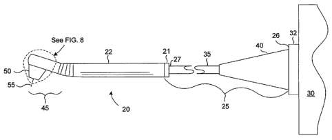
Referring more particularly to the drawings, FIG. 1 is a pictorial diagram of
a
delivery system capable of transferring laser energy to a treatment site. The
illustrated
Page 5 of 32
CA 02575667 2007-01-30
WO 2006/036337 PCT/US2005/028909
embodiment comprises a laser handpiece 20 that connects to an electromagnetic
energy
base unit, such as a laser base unit 30, using a linking element 25. The
linking element
25 may comprise a conduit 35, which may include one or more optical fibers,
tubing for
air, tubing for water, and the like. The linking element 25 further may
comprise a
connector 40 that joins the conduit 35 to the laser base unit 30. The
connector 40 may be
an identification connector as is described more fully in a U.S. Application
No.
11/192,334, filed 7/27/2005 and entitled IDENTIFICATION CONNECTOR FOR A
MEDICAL LASER HANDPIECE, the entire contents of which are incorporated herein
by reference. The laser handpiece 20 may comprise an elongate portion 22 and a
handpiece tip 45 formed as an extension of the elongate portion 22. The
elongate portion
22 may have disposed therein a plurality of optical fibers that may connect
to, or that are
the same as the optical fibers included in the conduit 35. A proximal (i.e.,
relatively
nearer to the laser base unit 30) portion 21 and a distal (i.e., relatively
farther from the
laser base unit 30) portion 50 may be disposed at respective proximal and
distal ends of
the laser handpiece 20. The distal portion 50 has protruding therefrom a fiber
tip 55,
which is described below in more detail with reference to FIG. R. As
illustrated, the
linking element 25 has a first end 26 and a second end 27. The first end 26
couples to a
receptacle 32 of the laser base unit 30, and the second end 27 couples to the
proximal
portion 21 of the laser handpiece 20. The connector 40 may connect
mechanically to the
laser base unit 30 with a threaded connection to the receptacle 32 that forms
part of the
laser base unit 30.
An embodiment of a connector 40 is illustrated in greater detail in FIG. 2.
The
illustrated embodiment comprises a laser beam delivery guide connection 60
that may
comprise, for example, a treatment optical fiber 65 capable of transmitting
laser energy
to the laser handpiece 20 (FIG. 1). The illustrated embodiment further
comprises a
plurality of ancillary connections comprising, in this example, a feedback
connection
115, an illumination light connection 100, a spray air connection 95, and a
spray water
connection 90, that may connect to the laser base unit 30 (FIG. 1). The
plurality of
ancillary connections further may comprise connections not visible in FIG. 2
such as an
excitation light connection and a cooling air connection.
The embodiment of the connector 40 illustrated in FIG. 2 further comprises a
threaded portion 70 that may mate with and thereby provide for c nnection to
the
receptacle 32 on the laser base unit 30 (FIG. 1).
Page 6 of 32
CA 02575667 2007-01-30
WO 2006/036337 PCT/US2005/028909
FIG. 3 is a perspective diagram of an embodiment of a module that may connect
to, and form a part of, a laser base unit 30 (FIG. 1) and that further may
accept connector
40 (FIG. 2). The illustrated embodiment comprises a plate 75 that may fasten
to a laser
base unit 30 by means of, for example, screws inserted into holes 76. The
module
comprises a receptacle 32 that may be threaded on an inside surface 80 to mate
with
threads 70 on the connector 40 (FIG. 2). (Threads are not shown in FIG. 3.)
The
embodiment of the module further comprises a laser energy coupling 61 mated to
the
laser beam delivery guide connection 60 (FIG. 2), the laser energy coupling 61
being
capable of providing laser energy to the delivery system. The embodiment
further
comprises a plurality of ancillary couplings including a spray air coupling
96, a spray
water coupling 91, a cooling air coupling 111, and an excitation light
coupling 106. The
embodiment still further comprises a feedback coupling and an illumination
light
coupling that are not visible in the diagram. One or more key slots 85 may be
included
to assure that the connector 40 connects to the receptacle 32 in a correct
orientation.
FIG. 4 is a front view of the embodiment of the module illustrated in FIG. 3.
The
view in FIG. 4 illustrates the plate 75 and the holes 76 that may be used to
secure the
plate module to a laser base unit, such as the laser base unit 30 illustrated
in FIG. 1.
Further illustrated are the laser energy coupling 61, feedback coupling 116,
the
illumination light coupling 101, the spray air coupling 96, the spray water
coupling 9 1,
the cooling air coupling 111, and the excitation light coupling 106. In
operation, the
spray water coupling 91 mates with and is capable of supplying spray water to
the spray
water connection 90 in the connector 40 (FIG. 2). Similarly, the spray air
coupling 9 6
mates with and is capable of supplying spray air to the spray air connection
95 in the
connector 40. Additionally, the illumination light coupling 101, the
excitation light
coupling 106, and the cooling air coupling 111 mate with and are capable of
supplying,
respectively, illumination light to the illumination light connection 100,
excitation light
to the excitation light connector(not shown), and cooling air to the cooling
air connection
(not shown) in the connector 40. Further, the feedback coupling 116 mates with
and is
capable of receiving feedback from the feedback connection 115 in the
connector 40 _
According to an illustrative embodiment, the illumination light coupling 101
and the
excitation light coupling 106 couple light from a light-emitting diode (LED)
or a laser
light source to, respectively, the illumination light connection 100 and the
excitation
light connection(not shown). One embodiment employs two white LEDs as a source
for
Page 7 of 32
CA 02575667 2007-01-30
WO 2006/036337 PCT/US2005/028909
illumination light. Also illustrated in FIG. 4 are key slots 85 that may
prevent the
connector 40 from being connected to the receptacle 32 in an incorrect
orientation.
FIG. 5 is a cross-sectional view of the module illustrated in FIGS. 3 and 4.
The
cross-section is taken along line 5-5' of FIG. 4, the line 5-5' showing cross-
sections of
the laser energy coupling 61, the feedback coupling 116, and the spray water
coupling
91. A water source 120 may supply water to the spray water coupling 91.
FIG. 6 is another cross-sectional view of the module illustrated in FIGS. 3
and 4.
The cross-section of FIG 6 is taken along line 6-6' of FIG. 4. The diagram
depicts cross-
sections of a light source (e.g., an LED 140) that may be capable of supplying
light to,
for example, one or both of the illumination light coupling 101 (FIG. 4) and
the
excitation light coupling 106. A pneumatic shutter 125 may control a position
of a
radiation filter 130 disposed in the laser base unit 30 so that the filter is
either inserted or
removed from a light path originating with the light source (e.g., the LED
140). For
example, one or more pneumatic shutter filters may be provided that enable
switching
between, for example, blue and white light that is coupled to the illumination
light
coupling 101 and the excitation light coupling 106 in order to enhance
excitation and
visualization.
FIG. 7 is a pictorial diagram of an embodiment of the conduit 35 shown in FIG.
1. The illustrated embodiment of the conduit 35 comprises a plurality of
proximal
members, such as, four proximal members comprising first proximal member 36,
second
proximal member 37, third proximal member 38, and fourth proximal member 39.
First,
second, and third proximal members 36, 37, and 38 may have hollow interiors
configured to accommodate one or more light transmitters or other tubular or
elongate
structures that have cross-sectional areas less than a cross-sectional area of
a hollow
interior of the conduit 35. According to one embodiment, first proximal member
36
comprises an illumination fiber, second proximal member 37 comprises an
excitation
fiber, and third proximal member 38 comprises a feedback fiber. First, second,
and third
proximal members 36, 37, and 38 may be arranged such that the hollow interior
of each
proximal member is in communication with a hollow interior of elongate body 22
(FIG.
1). This arrangement provides for a substantially continuous path for the
light
transmitters to extend from the proximal portion 21 to the distal portion 50
of the laser
handpiece 20. The third proximal member 38 may receive feedback (e.g.,
reflected or
scattered light) from the laser handpiece 20 and may transmit the feedback to
the laser
base unit 30 as is more particularly described below.
Page 8 of 32
CA 02575667 2007-01-30
WO 2006/036337 PCT/US2005/028909
The fourth proximal member 39 may comprise a laser energy fiber that receives
laser energy derived from an erbium, chromium, yttrium, scandium, gallium,
garnet (Er,
Cr:YSGG) solid state laser disposed in the laser base unit 30 (FIG. 1). The
laser may
generate laser energy having a wavelength of approximately 2.78 microns at an
average
power of about 6 W, a repetition rate of about 20 Hz, and a pulse width of
about 150
microseconds. Moreover, the laser energy may further comprise an aiming beam,
such
as light having a wavelength of about 655 nm and an average power of about 1
mW
transmitted in a continuous-wave (CW) mode. The fourth proximal member 39 may
be
coupled to or may comprise the treatment optical fiber 65 (FIG. 2) that
receives laser
energy from the laser energy coupling 61 (FIG. 4). The fourth proximal member
39
further may transmit the laser energy received from the laser base unit 30 to
the distal
portion 50 of the laser handpiece 20 (FIG. 1).
Although the illustrated embodiment is provided with four proximal members, a
greater or fewer number of proximal members may be provided in additional
embodiments according to, for example, the number of light transmitters
provided by the
laser base unit 30. In addition, the illustrated embodiment includes first and
second
proximal members 36 and 37 that have substantially equal diameters and a third
proximal member 38 that has a diameter less than either of the diameters of
the first and
second proximal members 36 and 37. Other configurations of diameters are also
contemplated by the present invention. In an exemplary embodiment, the
proximal
members connect with the connections in the connector 40 illustrated in FIG.
2. For
example, the first proximal member 36 may connect with the illumination light
connection 100 and the second proximal member 36 may connect with the
excitation
light connection (not shown). The third proximal member 38 may connect with
the
feedback connection 115, and the fourth proximal member 39 may connect with
the laser
beam delivery guide connection 60 and the treatment optical fiber 65.
Attachment of the
proximal members 36-39 to the connections may be made internal to connector 40
in a
manner known or apparent to those skilled in the art in view of this
disclosure and is not
illustrated in FIGS. 2 and 7.
FIG. 8 is a partial cut-away diagram of a handpiece tip 45 (cf. FIG. 1) that
couples with the laser base unit 30 by means of the linking element 25 and the
elongate
portion 22 of the laser handpiece 20. The illustrated embodiment, which is
enclosed by
an outer surface 46, may receive electromagnetic (e.g., laser) energy,
illumination light,
excitation light and the like from the laser base unit 30. Typically, the
laser energy and
Page 9 of 32
CA 02575667 2007-01-30
WO 2006/036337 PCT/US2005/028909
light are received by proximal members 36-39 (FIG. 7) as described above and
transmitted through waveguides, such as fibers 405 disposed in the elongate
portion 22
and the handpiece tip 45 as described below with reference to FIG. 10. For
example,
illumination light (not shown) may be received by the handpiece tip 45, such
as from
proximal members 36 and 37 (FIG. 7), carried by fibers 405 (FIG. 10, not shown
in FIG.
8), and directed toward a first mirror 425 disposed within the distal portion
50 of the
laser handpiece 20. The first mirror 425 in the illustrated embodiment directs
illumination light toward a plurality of tip waveguides 430 as is more
particularly
described below with reference to FIG. 12. Illumination light exiting the tip
waveguides
430 may illuminate a target area.
According to one embodiment, concentrated electromagnetic energy, such as
laser energy 401, is received (e.g., through fourth proximal member 39 (FIG.
7)) and
carried by an internal waveguide such as a treatment optical fiber 400. The
laser energy
401 may be directed toward a second mirror 420, which may eclipse at least a
part of the
first mirror 425 relative to a direction of propagation of the illumination
light to the first
mirror 425, the second mirror 4201ikewise being disposed in the distal portion
50 of the
laser handpiece 20. The second mirror 420 may reflect, and thereby direct, the
laser
energy 401 toward the fiber tip 55. Relative to the concentrated
electromagnetic energy
(e.g., laser energy 401), the illumination light may comprise an example of
additional
electromagnetic energy, so described because the illumination light and/or, as
described
below, excitation light, may comprise electromagnetic energy exhibiting a
relatively low
power level that is directed to illuminate a portion of a target surface that
may, for
example, surround a portion of a target surface to which the concentrated
electromagnetic energy is directed. The concentrated electromagnetic energy
(e.g., laser
energy 401) may be directed toward the target surface by the fiber tip 55.
In some embodiments, respective first and second mirrors 425 and 420 may
comprise parabolic, toroidal, and/or flat surfaces. FIG. 8 also illustrates a
simplified
view of a path 445 of cooling air received from a cooling air line (not shown)
in the
handpiece that may receive cooling air from the cooling air coupling 111 (FIG.
4).
The fiber tip 55 illustrated in FIG. 8 may be encased in a tip ferrule 105
having a
distal end. The tip ferrule 105, together with the fiber tip 55, may form a
removable,
interchangeable unit as is described more fully in U.S. Provisional
Application No.
60/610,75 7, filed September 17, 2004 and entitled, OUTPUT ATTACHMENTS
CODED FOR USE WITH ELECTROMAGNETIC-ENERGY PROCEDURAL
Page 10 of 32
CA 02575667 2007-01-30
WO 2006/036337 PCT/US2005/028909
DEVICE, the entire contents of which are included herein by reference to the
extent not
mutually incompatible.
FIG. 9 is a cross-sectional view of first proximal member 36 taken along line
9-9'
of FIG. 7 demonstrating that first proximal member 36 (as well as, optionally,
second
proximal member 37) may comprise three optical fibers 405 substantially fused
together
to define a unitary light emitting assembly or waveguide. In modified
embodiments, the
three optical fibers 405 may be joined by other means or not joined. According
to other
embodiments, one or more of the proximal members, such as the second proximal
member 37, can include different numbers of optical fibers 405. In an
illustrated
embodiment, the second proximal member 37 can include six optical fibers 405
(FIG. 9)
that begin to separate and eventually (e.g., at line 10-10' in FIG. 8)
surround a laser
energy waveguide, such as treatment optical fiber 400, as illustrated in a
cross-sectional
view of FIG. 10 taken along line 10-10' of FIG. 8 in the handpiece tip 45. In
another
exemplary embodiment, the second proximal member 37 can include three optical
fibers
405 (FIG. 9) and the first proximal member 36 can include three optical fibers
405 (FIG.
9), all six of which begin to separate and eventually (e.g., at line 10-10' in
FIG. 8)
surround a laser energy waveguide, such as treatment optical fiber 400 in the
handpiece
tip 45.
The third proximal member 38 may include six relatively smaller fibers 410, as
likewise is shown in the cross-sectional view of FIG. 10. Additional
waveguides, such
as additional fibers 410, may be disposed within the outer surface 46 and,
further, may
be configured to receive feedback from a target surface. For example, feedback
may
comprise scattered light 435 (FIG. 8) received from the fiber tip 55 in a
manner more
particularly described below. The scattered light 435 (i.e., feedback light)
may be
transmitted by third proximal member 38 (FIG. 7) to the laser base unit 30
(FIG. 1).
Fibers 410 are illustrated in FIG. 10 as being separate from each other, but
in additional
embodiments two or more of the fibers 410 can be fused or otherwise joined
together.
Fibers 405 and 410 can be manufactured from plastic using conventional
techniques,
such as extrusion and the like.
FIG. 11 is a cross-sectional diagram of another embodiment of the handpiece
tip
45, the cross-section being taken along line 10-10' in FIG. 8. FIG. 11 depicts
a laser
energy waveguide, such as treatment optical fiber 400 surrounded by
illumination
waveguides, such as fibers 405, and feedback waveguides, such as fibers 410,
all of
which are disposed within outer surface 46. In a manner similar to that
described above
Page 11 of 32
CA 02575667 2007-01-30
WO 2006/036337 PCT/US2005/028909
with reference to FIG. 10, the illumination waveguides, such as fibers 405 may
receive
light energy from the laser base unit 30 (FIG. 1) by way of illumination light
coupling
101 (FIG. 4), illumination light connection 100 (FIG. 2), and, for example,
proximal
members 36 and/or 37 (FIG. 7); and fibers 405 may direct the light to the
distal portion
50 of the laser handpiece 20 (FIG. 8).
In certain implementations involving, for example, caries detection, as
disclosed
in U.S. Application No. , filed August 12, 2005 and entitled CARIES
DETECTION USING TIMING DIFFERENTAILS BETWEEN EXCITATION AND
RETURN PULSES, the entire contents of which are incorporated herein by
reference,
fibers 405 further may function as both illumination and excitation
waveguides.
Feedback waveguides, such as fibers 410, may receive feedback light from the
fiber tip
55 (FIG. 8) and may transmit the feedback light to third proximal member 38,
which
couples to or comprises feedback connection 115. The feedback light may be
received
by the feedback coupling 116, which transmits the light to a feedback detector
145 (FIG.
5) disposed in the laser base unit 30 (FIG. 1). In other embodiments, such as
described
more fully in the above-referenced U.S. Application No. 11/192,334 entitled
IDENTIFICATION CONNECTOR FOR A MEDICAL LASER HANDPIECE, the laser
base unit 30 may additionally supply spray air, spray water, and cooling air
to the laser
handpiece 20.
FIG. 12 is a cross-sectional diagram of another embodiment of the laser
handpiece tip 45 taken along line 12-12' of FIG. 8. This embodiment
illustrates a fiber
tip 55 surrounded by a tip ferrule or sleeve 105, and, optionally, glue that
fills a cavity
130 around the fiber tip 55 to hold the fiber tip 55 in place. Tip waveguides
430 may
receive illumination light from second mirror 425 (FIG. 8) and direct the
illumination
light to a target. In some embodiments, fluid outputs 415, which are disposed
in the
handpiece tip 45, may carry, for example, air and water. More particularly,
illumination
light exiting from the illumination fibers 405 (cf. FIG. 11) is reflected by
second mirror
425 (FIG. 8) into the tip waveguides 430 (FIGS. 8 and 12). While a portion of
this
illumination light may also be reflected by second mirror 425 (FIG. 8) into
fiber tip 55,
fiber tip 55 receives, primarily, a relatively high level of laser energy 401
from treatment
optical fiber 400 (cf. FIG. 11), which laser energy, as presently embodied,
comprises
radiation including both a cutting beam and an aiming beam. In a
representative
embodiment, illumination light from the illumination fibers 405 that exits the
tip
waveguides 430 is white light of variable intensity (e.g., adjustable by a
user) for
Page 12 of 32
CA 02575667 2007-01-30
WO 2006/036337 PCT/US2005/028909
facilitating viewing and close examination of individual places of a target
surface, such
as a tooth. For example, a cavity in a tooth may be closely examined and
treated with
the aid of light from a plurality of tip waveguides 430.
A detailed illustration of an embodiment of a chamber for mixing spray air and
spray water in the handpiece tip 45 is shown in FIG. 8a. As illustrated, the
mixing
chamber comprises an air intake 413 connected to, for example, tubing (e.g., a
spray air
line, not shown) that connects to and receives air from, the spray air
connection 95 in the
connector 40 (FIG. 2). Similarly, a water intake 414 may connect to tubing
(also not
shown) that connects to and receives water from the spray water connection 90
in the
connector 40 (FIG. 2). The air intake 413 and the water intake 414, which may
have
circular cross-sections about 250 m in diameter, join at an angle 412 that
may
approximate 110 in a typical embodiment. Mixing may occur in a neighborhood
where
the air intake 413 and water intake 414 join, and a spray (e.g., atomized)
mixture 416 of
water and air may be ejected through a fluid output 415. The embodiment
illustrated in
FIG. 12 depicts three fluid outputs 415. These fluid outputs may, for example,
correspond to, comprise parts of, or comprise substantially all of, any of
fluid outputs
described in U.S. Application No. 11/042,824, filed January 24, 2005 and
entitled
ELECTROMAGNETICALLY INDUCED TREATMENT DEVICES AND METHODS,
the entire contents of which are incorporated herein by reference to the
extent
compatible, or, in other embodiments, structures described in the referenced
provisional
patent application may be modified to be compatible with the present
invention. The
fluid outputs 415 may, as illustrated in FIGS. 8 and 12, have circular cross-
sections
measuring about 350 m in diameter.
Scattering of light as described above with reference to FIG. 7 can be
detected
and analyzed to monitor various conditions. For example, scattering of an
aiming beam
can be detected and analyzed to monitor, for example, integrity of optical
components
that transmit the cutting and aiming beams. In typical implementations the
aiming beam
may cause little to no reflection back into the feedback fibers 410. However,
if any
components (such as, for example, second mirror 420 or fiber tip 55) is
damaged,
scattering of the aiming beam light (which may be red in exemplary
embodiments) may
occur. Scattered light 435 (FIG. 8) may be directed by the second mirror 425
into
feedback fibers 410 that may convey the scattered light to the laser base unit
30 (FIG. 1).
FIG. 13 is a flow diagram describing an implementation of a method of
analyzing
light, such as feedback light, in order to monitor integrity of optical
components. This
Page 13 of 32
CA 02575667 2007-01-30
WO 2006/036337 PCT/US2005/028909
implementation of the method receives feedback light (i.e., scattered light)
at step 500.
For example, the feedback light may be received by a light discerning device,
such as
photo detector 145 (FIG. 5), that forms an electrical signal from the feedback
light at step
505. Detection of scattered aiming beam light having an intensity above a
predetermined
threshold can trigger the laser base unit 30 or other machinery to provide an
indication of
error or potential error. According to the implementation of the method
illustrated in
FIG. 13, a magnitude of the electrical signal is compared with the
predetermined
threshold at step 510. An error indication is provided at step 515 if the
electrical signal
exceeds the predetermined threshold. That is, a magnitude of detected
scattered light
435 from the feedback fibers 410 and/or relative magnitudes of detected
scattered light
among the various feedback fibers 410 can be automatically analyzed and
compared with
predetermined optical-component failure criteria to provide additional
information to a
user regarding a type, location and/or severity of the potential optical-
component
problem. A feedback display can be provided on a monitor of the laser base
unit 30 (e.g.,
a color of blue) to indicate one or more of the above-described indications or
parameters.
The present invention contemplates constructions and uses of visual feedback
implements (e.g., cameras) as described in, for example, U.S. Provisional
Application
No. 60/688,109, filed June 6, 2005 and entitled ELECTROMAGNETIC RADIATION
EMITTING TOOTHBRUSH AND DENTIFRICE SYSTEM, and U.S. Provisional
Application No. 60/687,99 1, filed June 6, 2005 and entitled METHODS FOR
TREATING EYE CONDITIONS, on (e.g., attached) or in a vicinity of (e.g., on or
near,
attached or not, output ends) of electromagnetic energy output devices (e.g.,
lasers and
dental lasers), wherein such output devices, constructions and uses can be, in
whole or in
part, including any associated methods, modifications, combinations,
permutations, and
alterations of any constructions(s) or use(s) described or referenced herein
or
recognizable as included or includable in view of that described or referenced
herein by
one skilled in the art, to the extent not mutually exclusive, as described in
U.S.
Application No. 11/033,032, filed January 10, 2005 and entitled
ELECTROMAGNETIC
ENERGY DISTRIBUTIONS FOR ELECTROMAGNETICALLY INDUCED
DISRUPTIVE CUTTING, U.S. Application No. 11/033,043, filed January 10, 2005
and
entitled TISSUE REMOVER AND METHOD, U.S. Provisional Application No.
60/601,415, filed August 12, 2004 and entitled DUAL PULSE-WIDTH MEDICAL
LASER WI'EH PRESETS, U.S. Provisional Application No. 60/610,760, filed
September 17, 2004 and entitled LASER HANDPIECE ARCHITECTURE AND
Page 14 of 32
CA 02575667 2007-01-30
WO 2006/036337 PCT/US2005/028909
METHODS, and U.S. Application No. 09/848,010, filed May 2, 2001 and entitled
DERMATOLOGICAL CUTTING AND ABLATING DEVICE, the entire contents of
all which are incorporated herein by reference. In some embodiments, the
sensor may
comprise one or more visual feedback implements. The visual feedback implement
can
be used, for example, (a) in a form that is integrated into a handpiece or
output end of an
electromagnetic energy output device, (b) in a form that is attached to the
handpiece or
electromagnetic energy output device, or (c) in conjunction with (e.g., not
attached to)
the handpiece or electrornagnetic energy output device, wherein such
handpieces and
devices can facilitate cutting, ablating, treatments, and the like. Treatments
can include
low-level light treatments such as described in the above-referenced U.S.
Provisional
Application No. 60/687,991 entitled METHODS FOR TREATING EYE CONDITIONS
and U.S. Provisional Application No. 60/687,256, filed June 3, 2005 and
entitled
TISSUE TREATMENT DEVICE AND METHOD, the entire contents of both which are
expressly incorporated herein by reference.
For example, one implementation may be useful for, among other things,
optimizing, monitoring, or maximizing a cutting effect of an electromagnetic
energy
emitting device, such as a laser handpiece. The laser output can be directed,
for
example, into fluid (e.g., an air and/or water spray or an atomized
distribution of fluid
particles from a water connection and/or a spray connection near an output end
of the
handpiece) that is emitted from the handpiece above a target surface. An
apparatus
including corresponding structure for directing electromagnetic energy into an
atomized
distribution of fluid particles above a target surface is disclosed, for
example, in the
above-referenced U.S. Patent No. 5,574,247. Large amounts of laser energy, for
example, can be imparted into the fluid (e.g., atomized fluid particles),
which can
comprise water, to thereby expand the fluid (e.g., fluid particles) and apply
disruptive
(e.g., mechanical) cutting forces to the target surface. During a procedure,
such as an
oral procedure where access and visibility are limited, careful and close-up
monitoring
by way of a visual feedback implement of (a) interactions between the
electromagnetic
energy and the fluid (e.g-, above the target surface) and/or (b) cutting,
ablating, treating
or other impartations of disruptive surfaces to the target surface, can
improve a quality of
the procedure.
In certain embodiments, visualization optical fibers (e.g., a coherent fiber
bundle)
can be provided that are configured to transmit light from the distal portion
50 to the
proximal portion 21, for routing images (e.g., working-surface images)
acquired at or in
Page 15 of 32
CA 02575667 2007-01-30
WO 2006/036337 PCT/US2005/028909
a vicinity of the distal portion by a visual feedback implement. According to
some
embodiments, the visual feedback implement can comprise an image-acquisition
device
(e.g., CCD or CMOS camera) for obtaining or processing images from the distal
portion.
The visual feedback implement can be built-in or attached (e.g., removably
attached) to
the handpiece and, further, can be disposed at various locations on or in
connection with
the handpiece between the proximal portion and distal portion, or proximally
of the
proximal portion. According to this and any of the other embodiments described
herein,
one or more of the optical fibers described herein and the visualization
optical fibers can
be arranged, for example, outside of the handpiece envelope. A few
applications for the
presently-described visual feedback implement may include periodontal pockets
(e.g.,
diagnostic and treatment), endodontics (e.g., visualization of canals), micro-
dentistry,
tunnel preparations, caries detection and treatment, bacteria visualization
and treatment,
general dentistry, and airborne-agent and gas detection applications as
described in the
above-referenced U.S. Provisional Application No. 60/688,109.
According to another embodiment of the present invention, electromagnetic
radiation (e.g., one or more of blue light, white light, infrared light, a
laser beam,
reflected/scattered light, fluorescent light, and the like, in any
combination) may be
transmitted in one or both directions through one or more of the fibers
described herein
(e.g., feedback, illumination, excitation, treatment), in any combination.
Outgoing and
incoming beams of electromagnetic radiation can be separated or split, for
example,
according to one or more characteristics thereof, at the proximal portion or
laser base
unit using a beam splitter, such as a wavelength-selective beam splitter (not
shown), in a
manner known to those skilled in the art.
In a representative embodiment, the fluid outputs 415 (FIG. 12) are spaced at
zero (a first reference), one hundred twenTy, and two hundred forty degrees.
In another
embodiment, the six illumination/excitation fibers 405 and three feedback
fibers 410
(FIG. 11) are optically aligned with and coupled via second mirror 425 on, for
example,
a one-to-one basis, to nine tip waveguides 430 (FIGS. 8 and12). For example,
if nine
elements (e.g., six illumination/excitation fibers 405 and three feedback
fibers 410) are
evenly spaced and disposed at zero (a second reference, which may be the same
as or
different from the first reference), forty, eighty, one hundred twenty, one
hundred sixty,
two hundred, two hundred forty, two hundred eighty, and three hundred twenty
degrees,
then nine tip waveguides 430 may likewise be evenly spaced and disposed at
zero, forty,
eighty, one hundred twenty, one hundred sixty, two hundred, two hundred forty,
two
Page 16 of 32
CA 02575667 2007-01-30
WO 2006/036337 PCT/US2005/028909
hundred eighty, and three hundred twenty degrees. In another embodiment
wherein, for
example, the tip waveguides 430 are arranged in relatively closely-spaced
groups of
three with each group being disposed between two fluid outputs, the tip
waveguides 430
may be disposed at, for example, about zero, thirty-five, seventy, one hundred
twenty,
one hundred fifty-five, one hundred ninety, two hundred forty, two hundred
seventy-five,
and three hundred ten degrees. In one such embodiment, the tip waveguides 430
may
likewise be disposed at about zero, thirty-five, seventy, one hundred twenty,
one hundred
fifty-five, one hundred ninety, two hundred forty, two hundred seventy-five,
and three
hundred ten degrees. Further, in such an embodiment, the fluid outputs may be
disposed
between the groups of tip waveguides at about ninety-five, two hundred
fifteen, and three
hundred thirty-five degrees.
The cross-sectional views of FIGS. 10 and 11 may alternatively (or
additionally),
without being changed, correspond to cross-sectional lines 10-10' taken in
FIG. 8 closer
to (or next to) first and second mirrors 425 and 420 to elucidate
corresponding structure
that outputs radiation distally onto the first mirror 425 and the second
mirror 420. The
diameters of illumination/excitation fibers 405 and feedback fibers 410 may be
different
as illustrated in FIG. 10 or the diameters may be the same or substantially
the same as
shown in FIG. 11. In an exemplary embodiment, the illumination/excitation
fibers 405
and feedback fibers 410 in FIG. 11 comprise plastic constructions with
diameters of
about 1 mm, and the tip waveguides 430 in FIGS. 8 and 12 comprise sapphire
constructions with diameters of about 0.9 mm.
By way of the disclosure herein, a handpiece has been described that utilizes
electromagnetic energy to affect a target surface. In the case of dental
procedures using
laser energy, the handpiece can include an optical fiber for transmitting
laser energy to a
target surface for treating (e.g., ablating) a dental structure, such as a
tooth, a plurality of
optical fibers for transmitting light (e.g., blue light) for illumination,
curing, whitening,
and/or diagnostics of a tooth, a plurality of optical fibers for transmitting
light (e.g.,
white light) to a tooth to provide illumination of the target surface, and a
plurality of
optical fibers for transmitting light from the target surface back to a sensor
for analysis.
In the illustrated embodiment, the optical fibers that transrnit blue light
also transmit
white light. In accordance with one aspect of the invention herein disclosed,
a handpiece
comprises an illumination tube having a feedback signal end and a double
mirror
handpiece.
Page 17 of 32
CA 02575667 2007-01-30
WO 2006/036337 PCT/US2005/028909
In certain embodiments, the methods and apparatuses of the abo-ve embodiments
can be configured and implemented for use, to the extent compatible and/or not
mutually
exclusive, with existing technologies including any of the above-referenced
apparatuses
and methods. Corresponding or related structure and methods described in the
following
patents assigned to BioLase Technology, Inc., are incorporated herein by
reference in
their entireties, wherein such incorporation includes corresponding or related
structure
(and modifications thereof) in the following patents which may be (i) operable
with, (ii)
modified by one skilled in the art to be operable with, and/or (iii)
implenented/used with
or in combination with any part(s) of, the present invention according to this
disclosure,
that/those of the patents, and the knowledge and judgment of one skilled in
the art: U.S.
Patent No. 5,741,247; U.S. Patent No. 5,785,521; U.S. Patent No. 5,968,037;
U.S. Patent
No. 6,086,367; U.S. Patent No. 6,231,567; U.S. Patent No. 6,254,597, U.S.
Patent No. 6,
288,499; U.S. Patent No. 6,350,123; U.S. Patent No. 6,389,193; U.S. Patent No.
6,544,256; U.S. Patent No. 6,561,803; U.S. Patent No. 6,567,582; U.S. Patent
No.
6,610,053; U.S. Patent No. 6,616,447; U.S. Patent No. 6,616,451; U.S. Patent
No.
6,669,685; and U.S. Patent No. 6,744,790, all of which are commonly assigned
and the
entire contents of which are incorporated herein by reference.
One implementation may be useful for tailoring, optimizing or rnaximizing an
effect (e.g., cutting or ablating) of a laser. The laser output (e.g., from a
power fiber) can
be directed, for example, into fluid (e.g., an air and/or water spray or an
atomized
distribution of fluid particles from a water connection and/or a spray
connection near an
output end of the handpiece) that is emitted from a fluid output of the
handpiece above a
target surface (e.g., one or more of tooth, bone, cartilage and soft tissue).
The fluid
output may comprise a plurality of fluid outputs, concentrically arranged
around a power
fiber, as described in, for example, U.S. Application No. 11/042,824 and U.S.
Provisional Application No. 60/601,415. The power fiber may comprise, for
example, a
treatment optical fiber, and in various implementations may be coupled to an
electromagnetic energy source comprising one or more of a wavelength within a
range
from about 2.69 to about 2.80 microns and a wavelength of about 2.94 microns.
In
certain implementations the power fiber may be coupled to one or more of an
Er:YAG
laser, an Er:YSGG laser, an Er, Cr:YSGG laser and a CTE:YAG laser, and in
particular
instances may be coupled to one of an Er, Cr:YSGG solid state laser having a
wavelength of about 2.789 microns and an Er:YAG solid state laser having a
wavelength
of about 2.940 microns. An apparatus including corresponding structt:tre for
directing
Page 18 of 32
CA 02575667 2007-01-30
WO 2006/036337 PCT/US2005/028909
electromagnetic energy into an atomized distribution of fluid particles above
a target
surface is disclosed in the above-referenced U.S. Patent No. 5,574,247, which
describes
the impartation of laser energy into fluid particles to thereby apply
disruptive forces to
the target surface.
While this invention has been described with respect to various specific
examples
and embodiments, it is to be understood that the invention is not limited
thereto and that
it can be variously practiced. Multiple variations and modification to the
disclosed
embodiments will occur, to the extent not mutually exclusive, to those skilled
in the art
upon consideration of the foregoing description. Additionally, other
combinations,
omissions, substitutions and modifications will be apparent to the skilled
artisan in view
of the disclosure herein. Accordingly, the present invention should not be
limited by the
disclosed embodiments, but is to be defined by reference to the appended
claims.
Page 19 of 32